Assignment 6-Frontal Crash Simulation Challenge
OBJECTIVE:
To perform frontal crash analysis on the neon car model using Hypermesh and RADIOSS and discuss the simulation results obtained.
PROCEDURE:
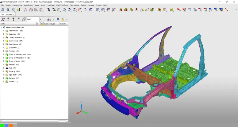
1) Initially, the given model is imported into HyperCrash.
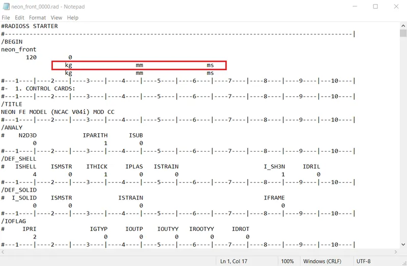
Before importing, the unit system used in the model is checked by opening the Starter file (0000.rad) using NotePad. From the starter file it is found that the unit system used is [Kg mm ms].
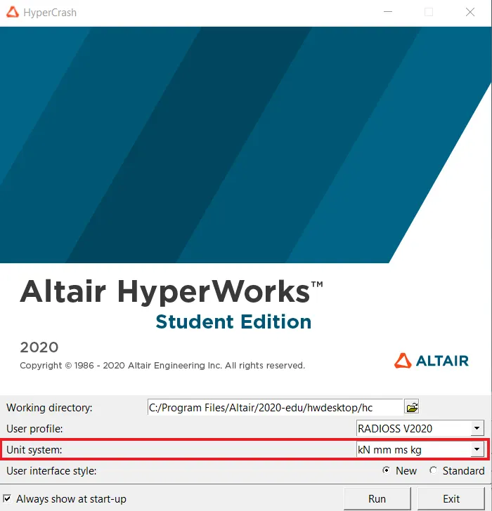
The Unit System can be selected while opening the HyperCrash Application,
2) The model is checked for any penetration or intersections. The presence of these will lead to energy errors and therefore negatively affect the results.
Menu>Quality>Check Intersections of Tree Selection
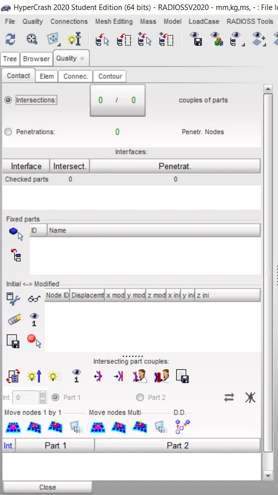
No penetration or intersections are found to be present in the model.
3) Next, the model weight is compared with the full-scale 300k nodes model. Added masses are used to reach target weight of 700kg while getting CG about the required range.
Menu>Mass>Balancing
Due to the limitation in the number of nodes for the student version many components are missing in the model. The current mass of the model is found to be approximately 188 Kg.
By using the isolate tool the current position of the COG can be viewed.
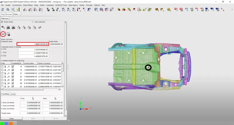
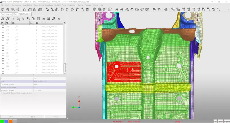
To move the COG to the required position located at the middle of the cross beam, the masses have to be added accordingly. The masses are added at the suitable locations to represent the mass of the seat, passengers etc.
Added Mass > Right Click > Create New > Type =1 > [MASS]Added Mass: Enter the amount of mass to be added > [grnod_ID]Support: Define the nodes where mass is to be added by selecting in the graphics > after selecting hit YES > Save
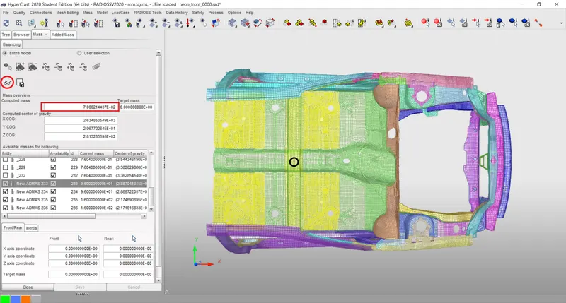
Thereby the overall mass of the model is brought to 700 Kg and the COG is brought to the required position.
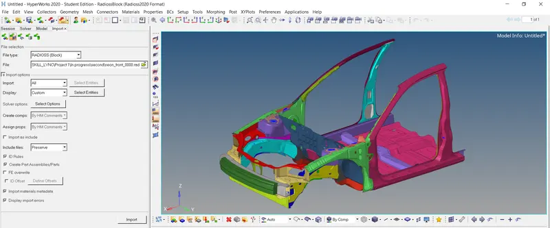
4) The model is now exported from HyperCrash and is imported into HyperMesh as the rest of the operations are carried out in Hypermesh.
5) The Contact Interface for the model is defined. Type 7 interface has been used, which is a node to surface contact with non-linear stiffness. Since Self-Impact has to be defined in the model, for both the Slave and Master the entire given model will be selected.
Solver Browser>Right Click>Create>INTER>Type 7
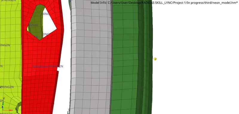
All the recommended properties are applied under the Type 7 contact.
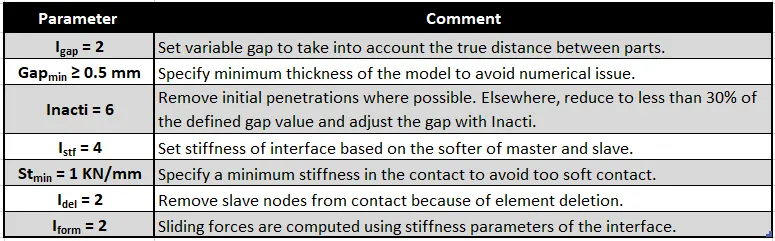
Also, Fric = 0.2
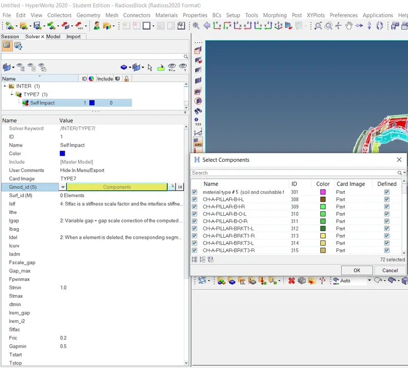
To obtain the axial force received on the rails from the bumper, a Type 7 Contact Interface is created between the bumper and the headlight bracket. The bumper is selected as the master while the headlight bracket is selected as the slave.
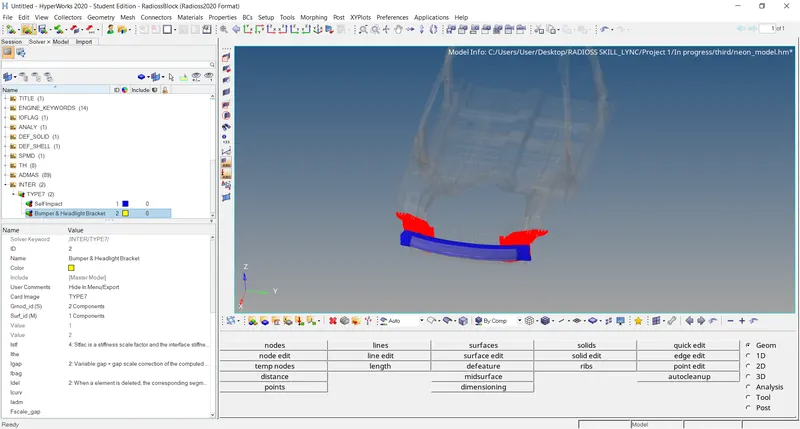
6) A rigid wall has to be created. For this a temporary node is created at the middle of the bumper. This node will be used as reference for creating the rigid wall. The temporary node is translated a certain distance away from the bumper so that there is a certain gap present between the rigid wall and the front bumper of the car model.
Solver Browser>Right Click>Create>RWALL>PLANE
An ‘Infinite Plane’ type rigid wall is selected. Under Engineering Data for ‘XM, YM, ZM’, the newly created temporary node is selected. Also, since the normal of the rigid wall plane is to be oriented towards the negative X-axis, under ‘Normal’, the value ‘-1,0,0’ (i.e. x=-1) is given.
The search distance, Dsearch, is set as 1000 mm. All the nodes that come within this range will be considered as slave nodes. Also, frictional parameters for the rigid wall have to be provided for when the slave nodes come in contact with the rigid wall. The ‘Slide’ option is set to ‘2: Sliding with friction’ and the frictional coefficient value, ‘FRIC’ is set to 0.1.
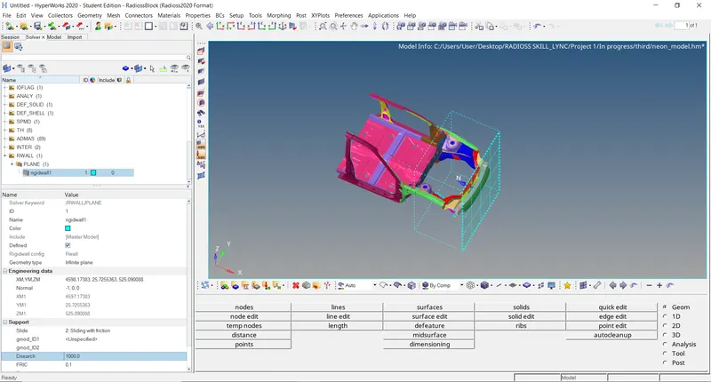
7) An initial velocity of 35 mph has to be provided to the car model. The unit system used in our model is mm/ms, therefore 35 mph becomes 15.6464 mm/ms on conversion.
Solver Browser>Right Click>Create>BOUNDARY CONDITIONS>INIVEL
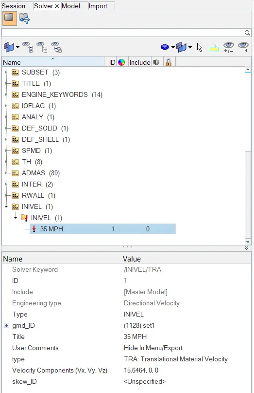
Since the velocity is to be applied only in the translational X direction, the Velocity Component is specified as ’15.6464, 0, 0’.
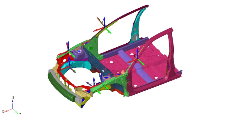
8) Sectional Forces at the Rails, Shotgun and A-Pillar have to be obtained to see how the forces are being transmitted and thereby study the frontal impact load path.
For defining the section, frames have to be created at the required locations.
Solver Browser>Right Click>Create>FRAME>MOV
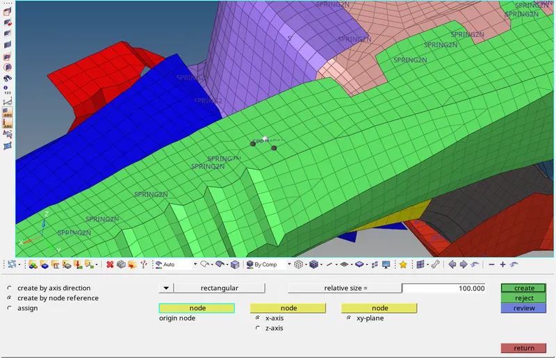
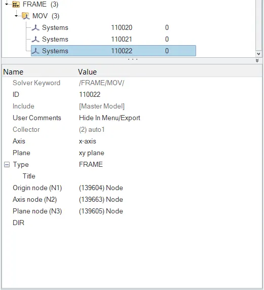
To create the sections,
Solver Browser>Right Click>Create>SECT>SECT
Also, ‘delta T’ set to 0.1, ‘alpha’ value is set to 0.6, ‘ISAVE’ is set to 0 and ‘Iframe’ is set to 12.
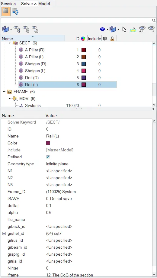
The Frames and Sections are created at all the required locations.
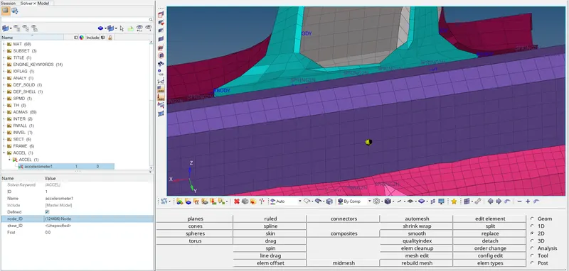
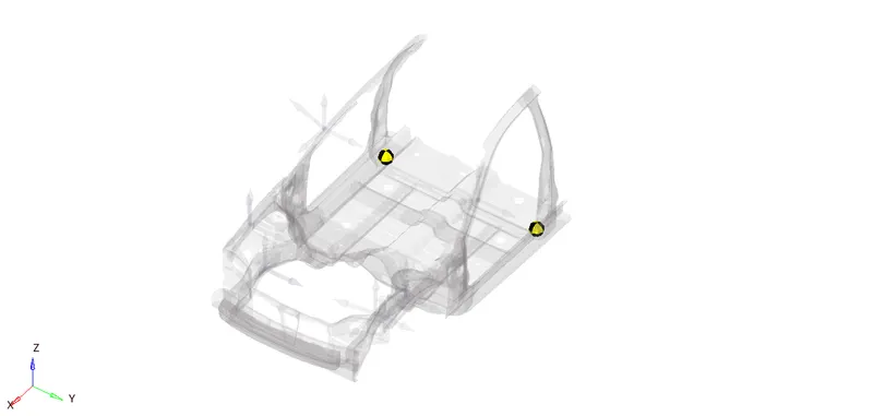
9) Accelerometers have to be created at the base of the B pillar(on B pillar rocker) on both sides of the car body to obtain the acceleration curve.
Solver Browser>Right Click>Create>ACCEL
10) The amount of intrusion on the dash wall need to be measured and if the intrusions are beyond a certain limit, it can compromise the safety of the passengers.
The intrusion is measured with the help of spring elements. The spring element is created between the indicated node and the cross beam.
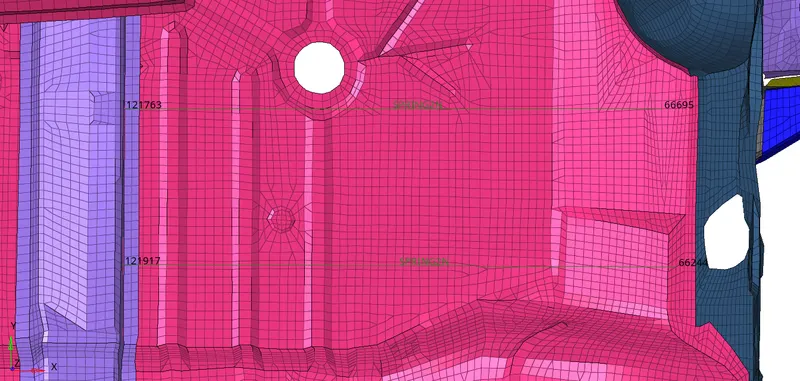
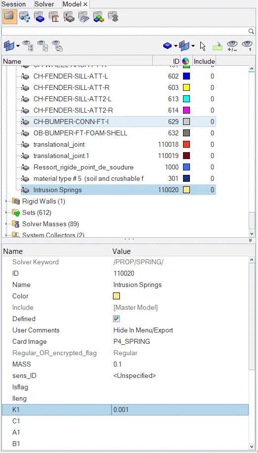
The change in length of the spring will give the amount of intrusion. The mass of the spring is set to 0.1 Kg and stiffness of the spring is set to a small value of 0.001.
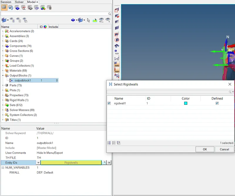
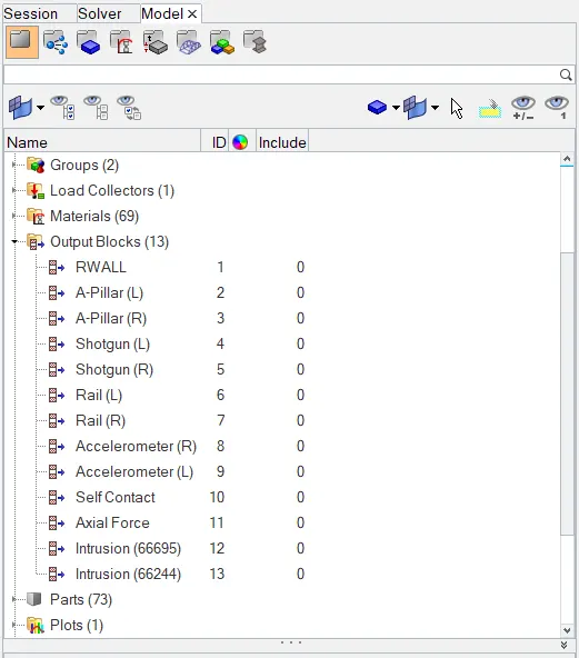
11) The output has to be requested by defining the output blocks. Global Variables are requested by default. Additional time history file has to be requested for the Sections, Accelerometer, Springs(Intrusions) and the Rigid Wall.
Model Browser>Right Click>Create>Output Block
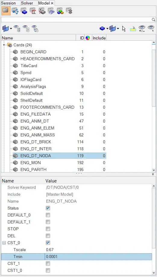
12) The time step for the simulation has to be defined. The timestep value, Tmin is set to 0.0001 under the ENG_DT_NODA card.
Model Browser>CARDS>ENG_DT_NODA>Tmin: 0.0001
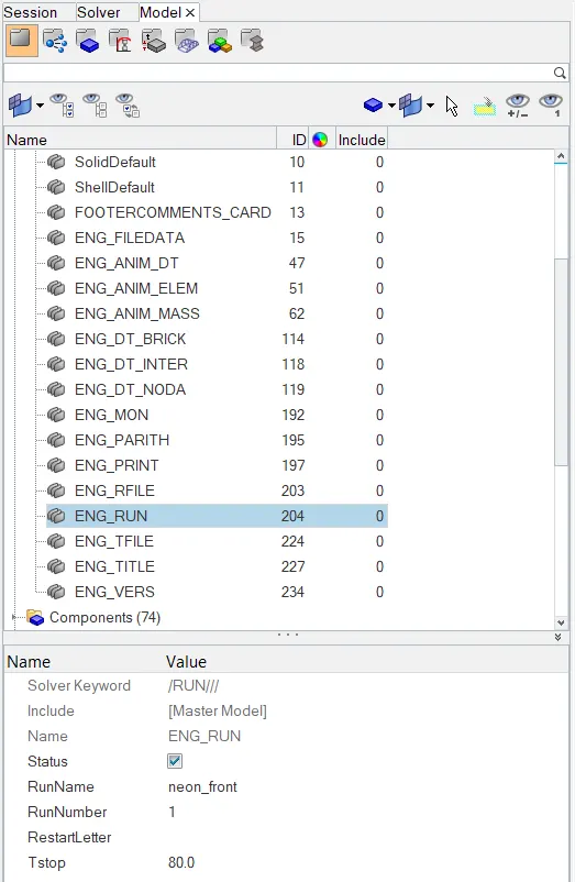
Also, the Run time is set as 80 ms under the ENG_RUN card.
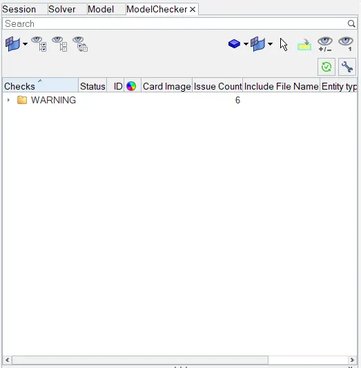
13) After completing all these steps the model is checked for any errors by running the Model Checker. If any errors are found, it should be rectified before running the simulation. Warnings can be ignored.
Tools>Model Checker>RadiossBlock
14) Now the simulation can be run using the RADIOSS solver.
Analysis > Radioss > click ’save as’ to save the file to the required directory >export options: ‘all’ > run options: ‘analysis’ > run number: ‘1’ > options: ‘-nt 4’(number of threads set to 4, for faster simulation) > Radioss
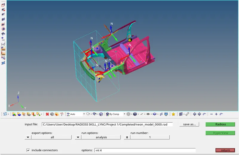
On completion of the simulation, a pop up window opens showing the run summary.
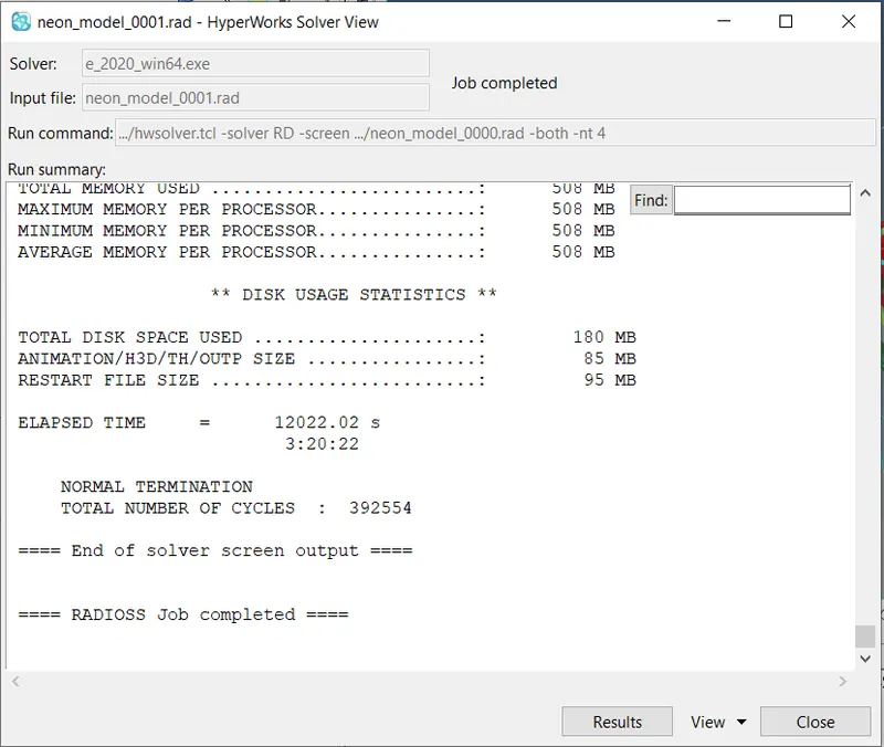
15) After the simulation is completed, the required values such as ‘Energy error percentage’ and ‘Mass error’ can be viewed by opening the engine output file (file ending with 0001.out) using Notepad.
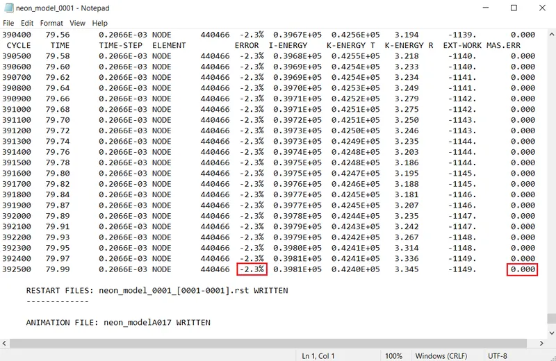
The energy error obtained is -2.3% which is within the acceptable range. Also, the mass error is 0. Hence the result is acceptable.
RESULTS:
- ANIMATION:
To visualize the simulation results as an animation, HyperView is used. For this, the animation file(file ending with .h3d) is loaded in Hyperview.
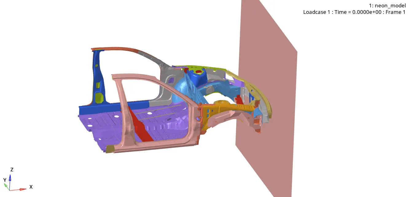
Von Misses Stress Contour:
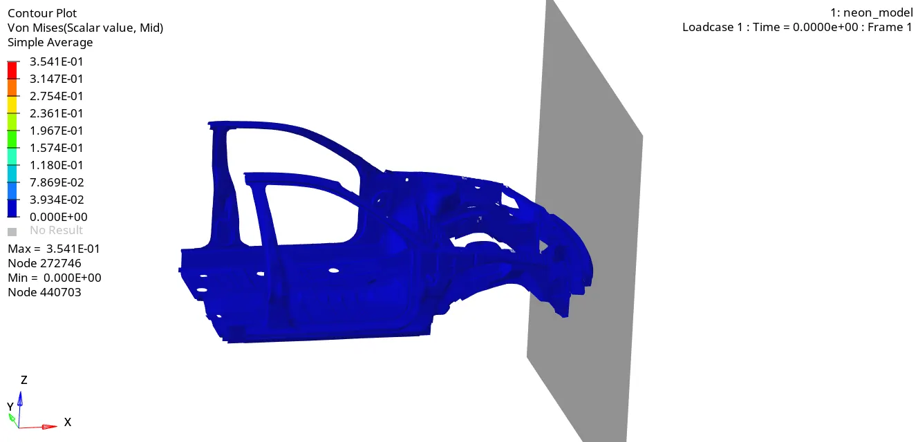
The above animation shows the von misses stress developed in the car. From the animation, it can be observed that, on impacting the rigid wall, the bumper starts deforming first and then the energy is getting transferred through the rails and the shotgun to the A-pillars. Thus the impact energy is fairly distributed along the body.
As the model is a reduced scale model and components like engine blocks, suspension system etc., are removed due to software constraints, the simulation does not represent such a frontal crash scenario accurately.
The maximum von-misses stress obtained is 0.3541 kN/mm2.
PLOTTING GRAPHS:
- GLOBAL VARIABLES:
To plot the graph, HyperGraph is opened.
Under ‘data file’, the Time History File ( file ending with T01) is loaded.
(X Type: Time > Y type: Global Variables > Y Request: Internal Energy, Kinetic Energy, Contact Energy, Hourglass Energy and Total Energy > Y Component: MAG > Apply)
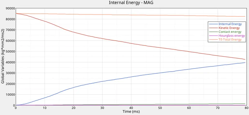
As the graph shows, the Kinetic Energy is maximum at the beginning and starts to decrease once the car model hits the rigid wall. This Kinetic Energy gets converted to Internal Energy as the model deforms as can be seen in the graph by the rise of the Internal Energy Curve. The Maximum Kinetic Energy of 85322.76 J is present at T=0 and gets reduced to 42580.45 J by the end of the simulation, at T=80 ms. Whereas, the Internal Energy is 0 at T=0 and reaches its maximum value of 39656.52 J at T=80 ms.
As the crush tube undergoes deformation, due to self-impact, there is an interaction between the slave nodes and the master segments and as a result resistive forces are generated to keep the slave nodes out of the contact gap. Thus the contact energy slightly increases thereby reducing the total energy.
The Hourglass Energy is found to be negligible due to the use of QEPH element formulation.
- SECTIONAL FORCES:
Sectional Forces at the Rails, Shotgun and A-Pillar are obtained to see how the forces are being transmitted through the model and thereby study the frontal impact load path.
Rail:
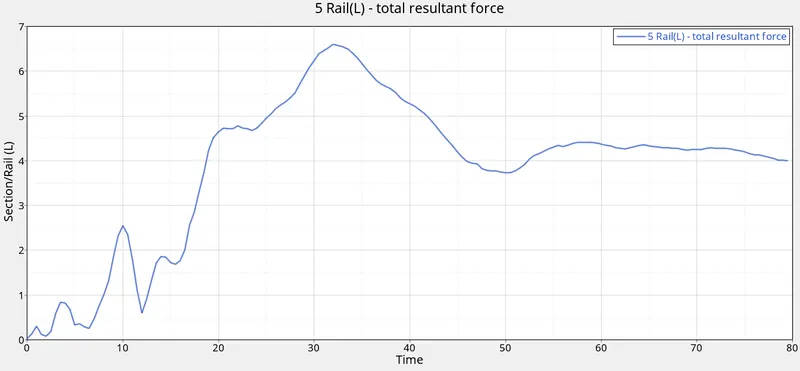
The maximum sectional force at left rail is 6.596 kN at around 32 ms.
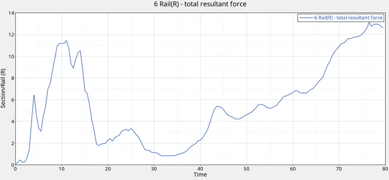
The maximum sectional force at right rail is 13.139 kN at around 76.5 ms.
A-Pillar:
The maximum sectional force at left A-Pillar is 2.389 kN at around 73.5 ms.
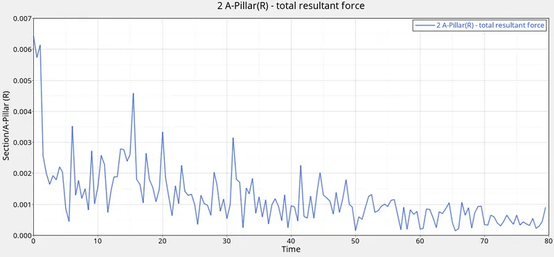
The maximum sectional force at right A-Pillar is 0.00642 kN observed at the beginning.
Shotgun:
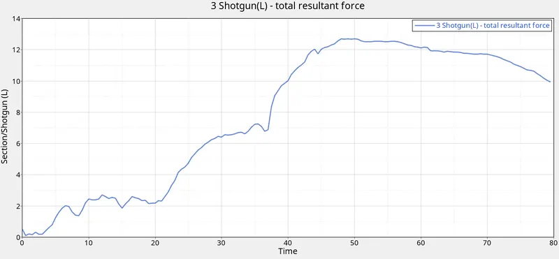
The maximum sectional force at left shotgun is 12.710 kN at around 48 ms.
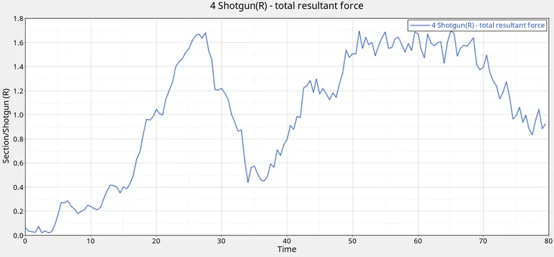
The maximum sectional force at right shotgun is 1.694 kN at around 51 ms.
- AXIAL FORCE:
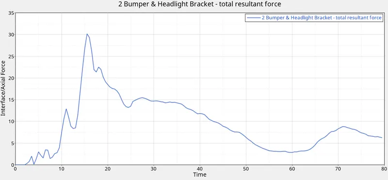
The maximum Axial force received on the rails from bumper is 30.181 kN at around 15.5 ms.
- ACCELEROMETER:
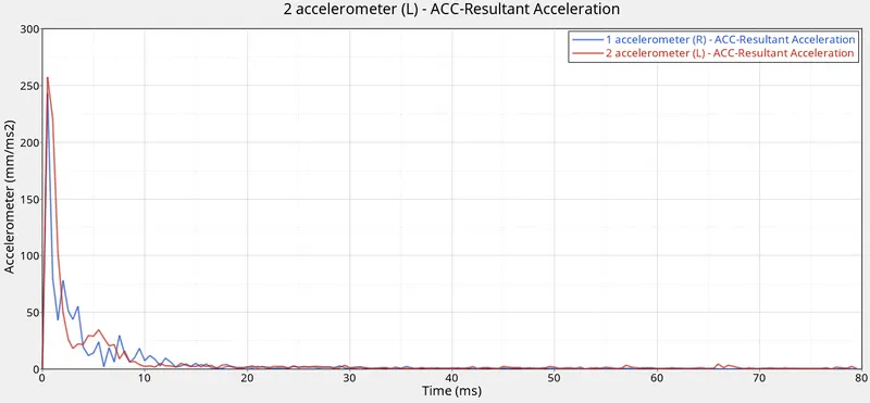
Acceleration is the rate of change of velocity. Initially the acceleration shot up as the vehicle is starting from stand still and an initial velocity is applied to the model. Then on impact with the rigid wall there is deceleration.
- INTRUSION:
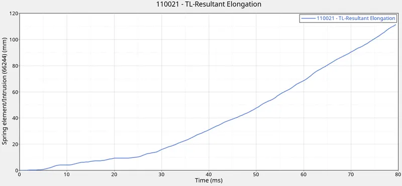
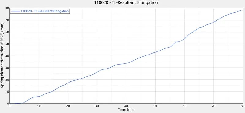
The intrusion at node 66695 is found to be 78.06 mm and the intrusion at node 66244 is found to be 111.30 mm. From these values it can be concluded that for the area under study, the intrusions are very small and hence won’t cause any severe injuries to the driver of the car.
CONCLUSION:
Frontal Crash Simulation was carried out on the given neon car model using RADIOSS solver after doing the Analysis setup using the HyperMesh and HyperCrash Pre-Processors and the results obtained were studied. From the simulations it was observed that there was minimum deformation in the cabin thereby ensuring the safety of the passengers inside.