Assignment 2-RADIOSS Engine File Editing & 3D Meshing Challenge
OBJECTIVES:
- To check the material properties of the rail component and calculate the speed of sound in steel rail.
- To calculate the time takes for a shock wave to travel from one end of the rail to the other.
- To calculate the time for sound to travel the length of the rail.
- To edit the engine file so that the stress wave can be monitored, moving from one end of the rail to the other during impact.
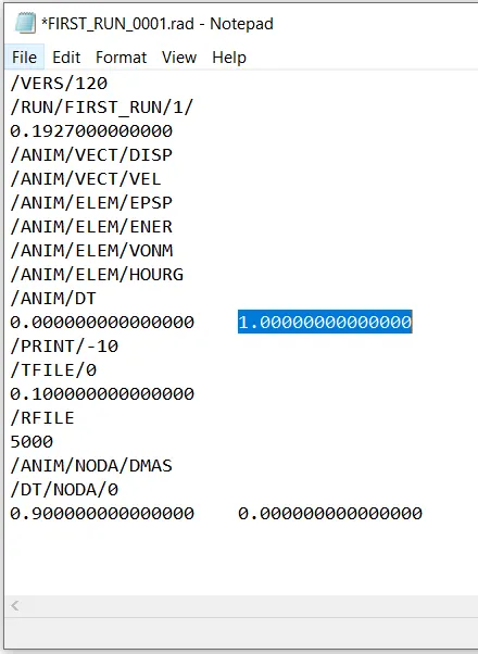
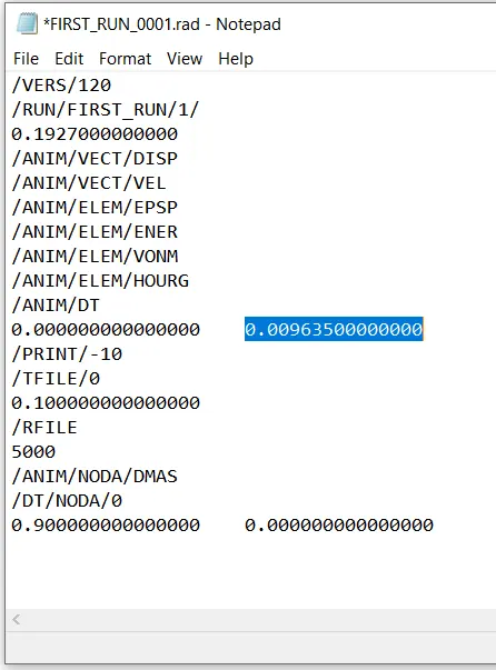
- To set the frequency of animation output to a time that will give 20 animation steps. (/ANIM/DT)
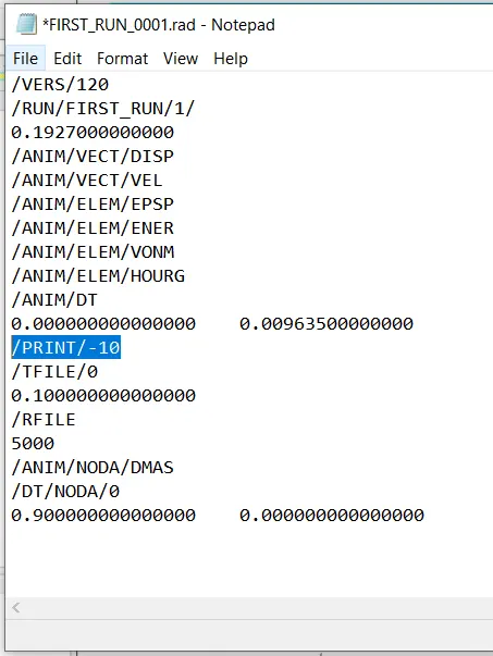
- To change /print -10.
- To perform 3d meshing(Tetra mesh and Hex mesh) by following the given quality parameters. (Target tet size=5mm, hex size=10mm, tet collapse=0.15.)
PROCEDURE:
1) Check the material properties of the rail component and calculate the speed of sound in steel rail:
The ‘Starter Input Deck’ contains all the information regarding the model such as nodes, elements, material properties, boundary conditions, interfaces, initial velocities etc.
To obtain the material properties of the rail component, the Starter Input Deck file with the name ‘FIRST_RUN_0000.rad’ is opened using Notepad.
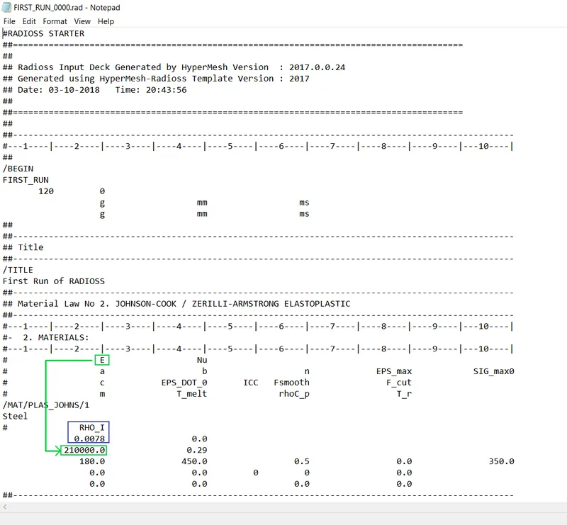
From the material properties,
Young’s Modulus(E) = 210000.0
Density(`rho`) = 0.0078
Therefore,
speed of sound, c = `root 2(E/rho)` = `root 2(210000/0.0078)` = 5188.745 mm/ms
2) Calculate the time takes for a shock wave to travel from one end of the rail to the other:
Given,
Length of the rail, l = 1000 mm
Therefore,
`trianglet` = `l/c` = `1000/5188.745` = 0.1927 ms
3) Calculate the time for sound to travel length of rail:
Time for sound to travel length of rail = 0.1927 ms
4) Edit the engine file so that the stress wave can be monitored, moving from one end of the rail to the other during impact -this will require a termination time equal to the time it takes for the sound to travel the length of the rail(set on/RUN card):
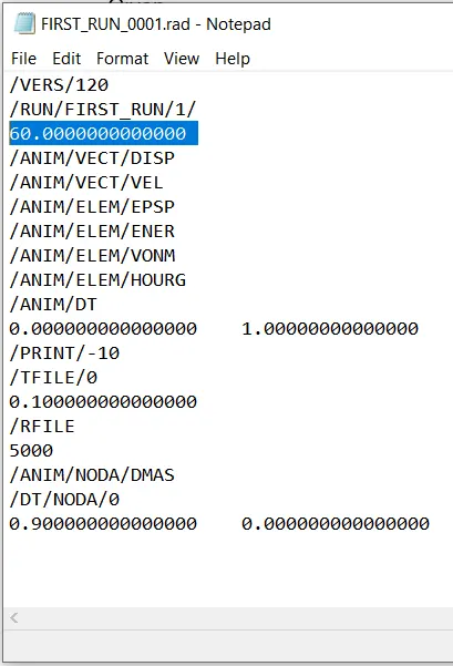
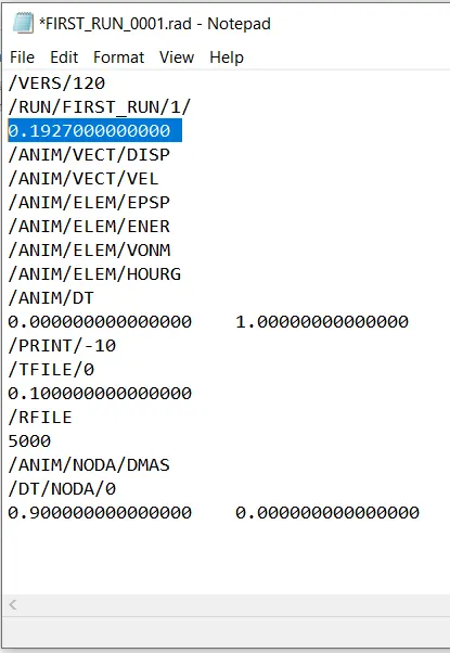
To edit the engine file, the file ‘FIRST_RUN_0001.rad’ is opened in Notepad.
The termination time is changed to 0.1927 ms.
5) Set the frequency of animation output to a time that will give 20 animation steps. (/ANIM/DT):
Frequency = `("Termination Time")/("Animation Steps")` = `0.1927/20` = 0.009635
6) Change /print -10 :
7) Perform 3d meshing(Tetra mesh and Hex mesh) by following the given quality parameters:
- Creating Tetramesh on Housing and Hub Components:
Quality Parameters:
Target Element Length: 5mm
Tet collapse: 0.15
- Hub Component:
Step 1: Import the geometry into HyperWorks.
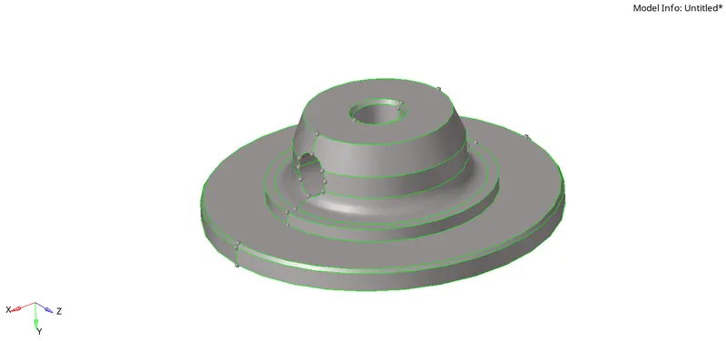
Step 2: Perform Geometry Cleanup on the model if required.
Step 3: Meshing the component with 2D Tria elements
2D Tria elements are first generated on the surface of the component. Then from the 2D shell elements the 3D Tetramesh can be generated.
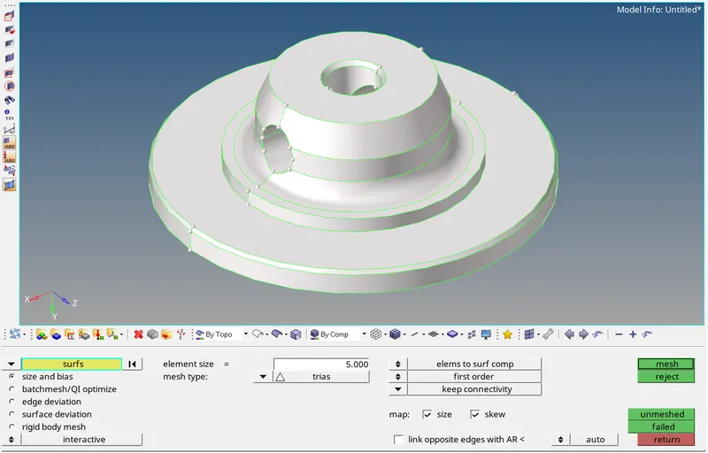
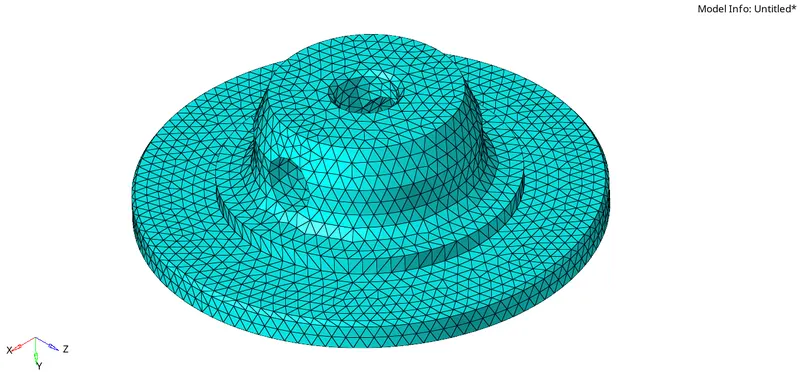
Step 4: Creating 3D Tetramesh from the 2D Tria elements
The 'Tetramesh parameters' are edited before tetrameshing to ensure the quality of tetra elements.

(3D>tetramesh>tetra mesh>fixed trias/quads to tetra mesh=elems>mesh)
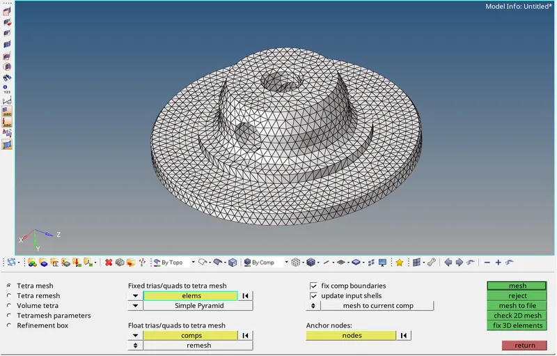
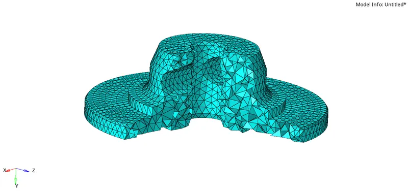
Mask some elements to see the interior of the component, to ensure that 3D Tetramesh has been carried out properly.
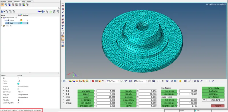
Step 5: Quality Check
The tet collapse of the tetra elements is checked. (F10 > 3d > tet collapse). Ensure that there are zero elements failing the ‘Tet collapse’ value.
2. Housing Component:
Step 1: Import the geometry into HyperWorks.
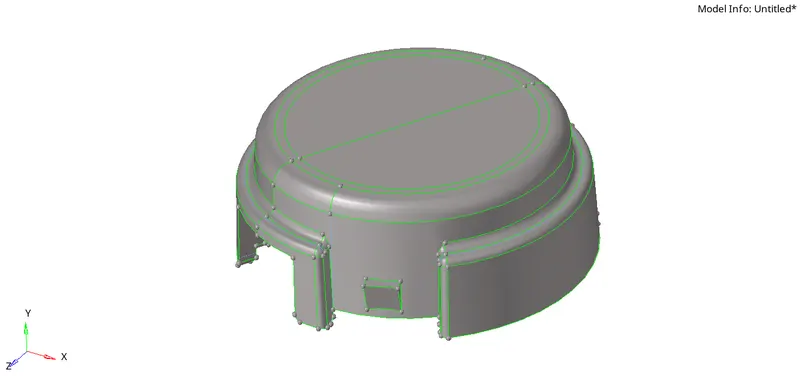
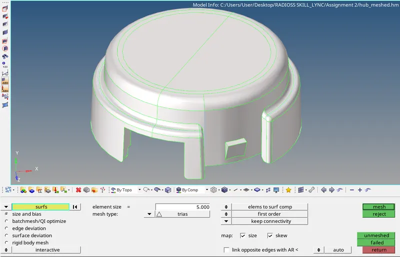
Step 2: Meshing the component with 2D Tria elements
2D Tria elements are first generated on the surface of the component.
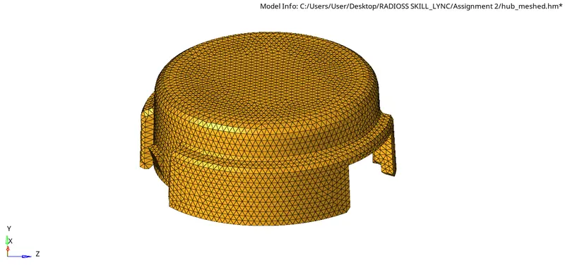
Step 3: Creating 3D Tetramesh from the 2D Tria elements
(3D>tetramesh>tetra mesh>fixed trias/quads to tetra mesh=elems>mesh)
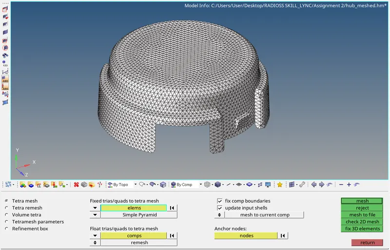
Mask some elements to see the interior of the component, to ensure that 3D Tetramesh has been carried out properly.
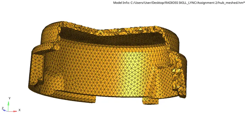
After meshing, the ‘tet collapse’ of the Tetra elements need to be checked. (F10 > 3d > tet collapse)
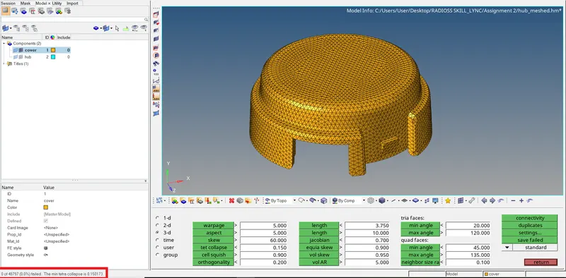
FINAL MODEL IMAGE:
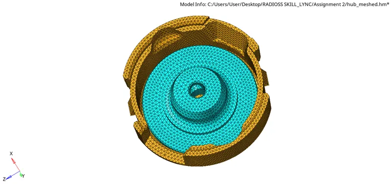
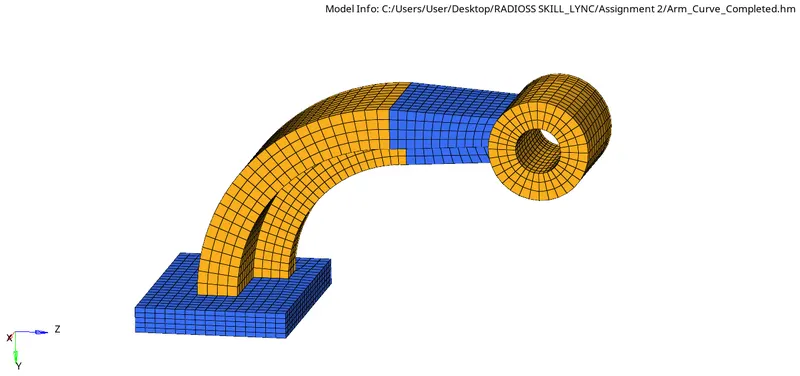
B. Hexameshing on the Arm Bracket Component:
Quality Parameters :
Hex Size : 10 mm
Step 1: Import the geometry into HyperWorks.
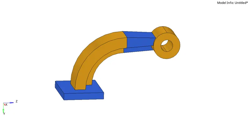
Step 2: Perform Geometry Cleanup on the model, if required.
Step 3: Meshing the component section by section
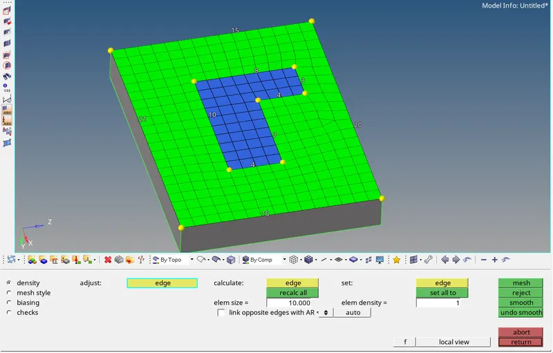
- Base:
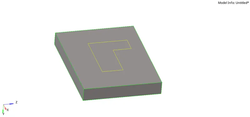
2D meshing using quad elements is first performed on the surface of the base. Then from the 2D shell elements the 3D Hexamesh can be generated.
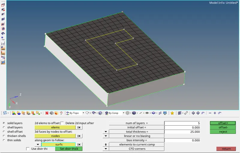
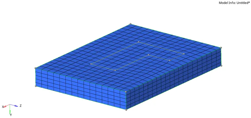
Using the ‘Element Offset’ tool, the 2D Quad elements are converted into Hexa Elements.
2. Arm Curve:
To mesh the arm curve the ‘spin’ tool can be used. To use the spin tool, first, the centre of the curve needs to be found. This can be done using the ‘distance’ tool.
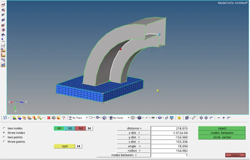
Using ‘Spin’ Tool to create 3D Hexamesh,
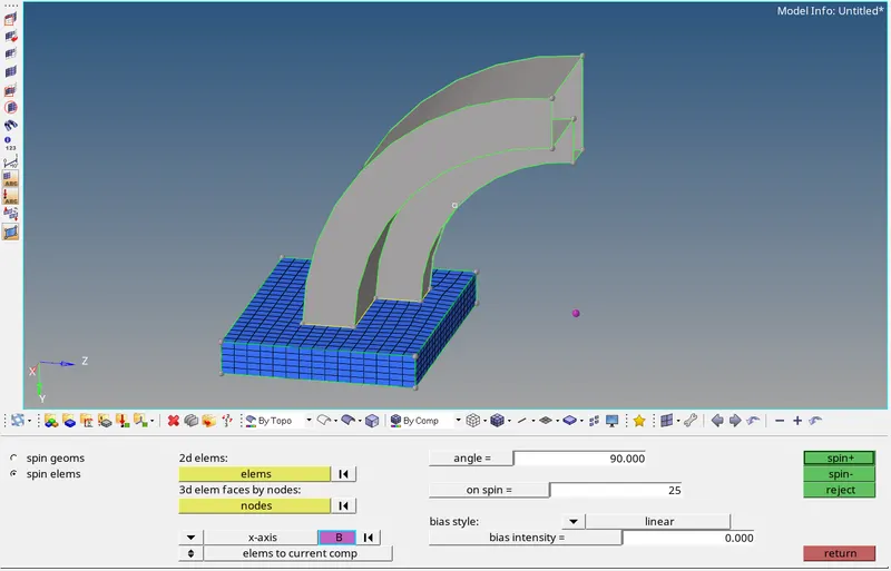
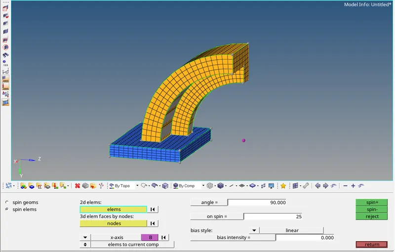
3. Arm Straight:
For meshing the arm straight, ‘Linear Solid’ tool is used.
While using the linear solid tool, ‘from’ elements(i.e. elements on one of the end faces of the part) and the ‘to’ elements(i.e. elements on the other end of the part) need to be selected.
Therefore, to obtain the ‘from’ elements, the ‘faces’ tool is used to create 2D quad elements on the faces of the 3D Hex elements.
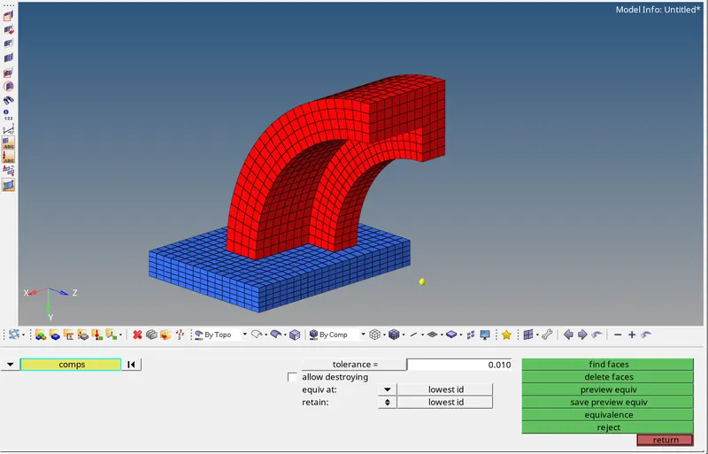
To obtain the ‘to’ elements, the other end of the arm straight needs to be meshed with the same number of elements as present on the surface containing the ‘from’ elements.
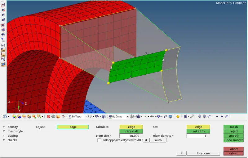
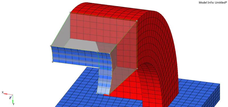
Using ‘Linear Solid’ tool to create 3D Hexamesh,
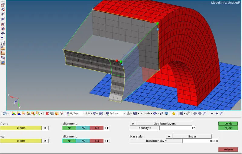
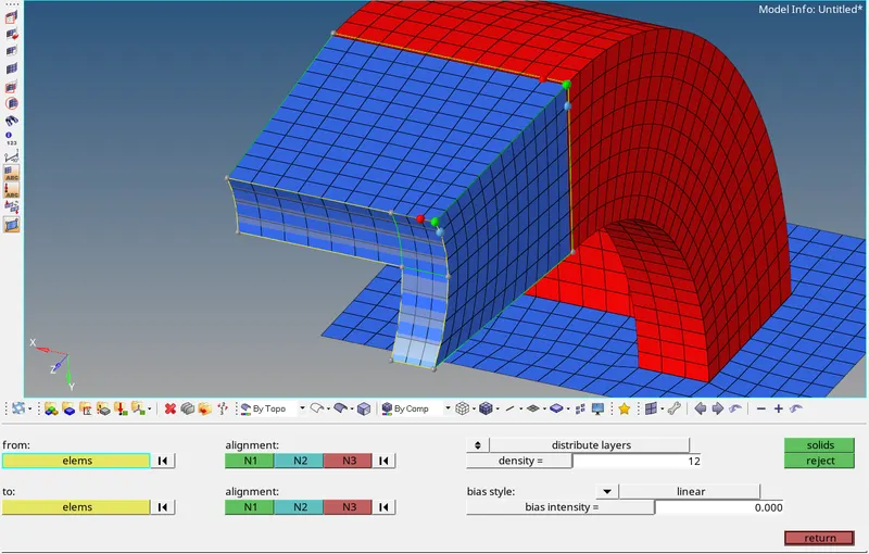
4. Boss:
The cross-section of the Boss is meshed first using quad elements.
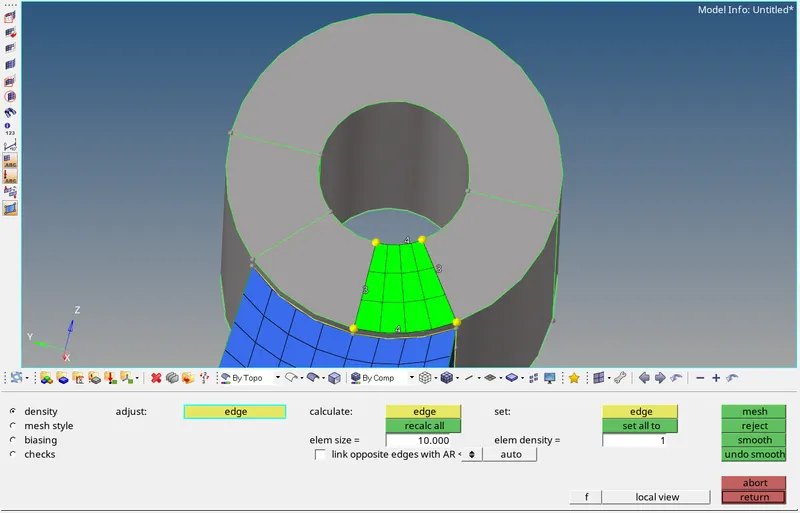
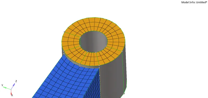
Then, using ‘solid map’, Hexamesh is generated for the Boss.
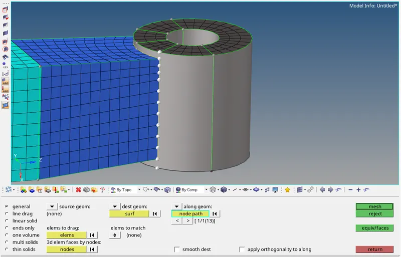
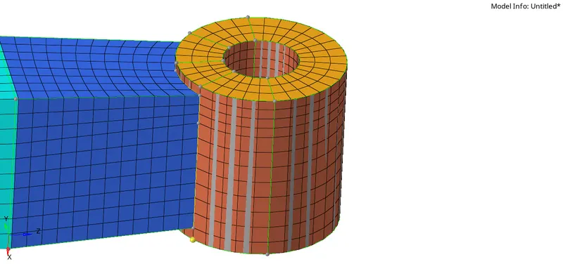
FINAL MODEL IMAGE:
CONCLUSION:
The speed of sound in steel rail and the time takes for a shock wave to travel the length of rail was calculated after obtaining the material properties of the rail component from the Starter Input Deck. To input the calculated values, the Engine File was edited. Also, the given models were 3D meshed with Tetra and Hex elements according to the given quality parameters.