Week- 5 - Solid meshing
OBJECTIVE:
To perform Solid Meshing on the given rearview mirror component by following the given Quality Criteria.
2D element Quality Criteria:
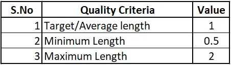
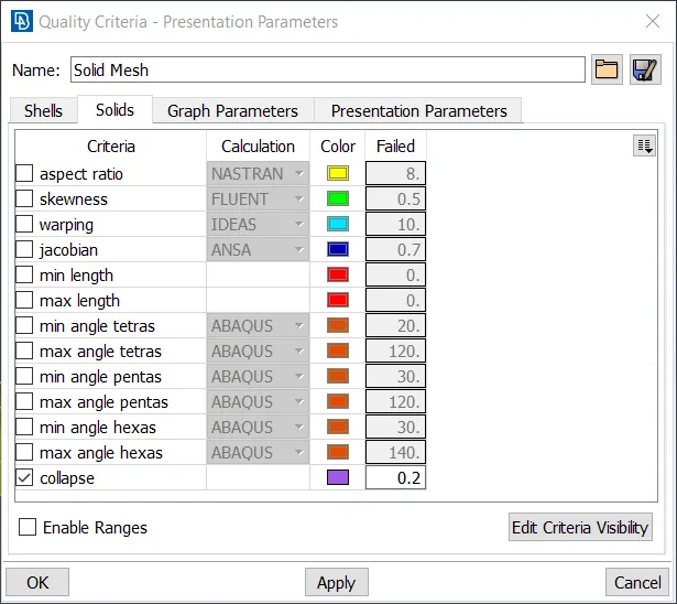
Tetra elements Quality Criteria:

PROCEDURE:
1) Open the given model in ANSA.
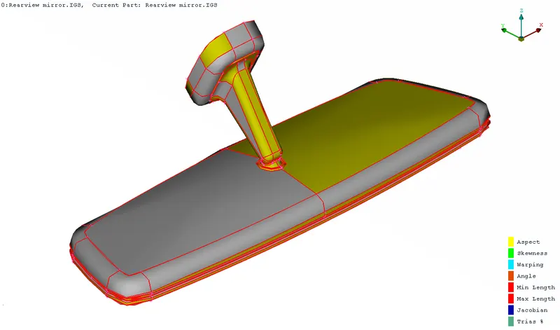
The surfaces in the model are not stitched together as can be seen by the presence of the single cons(red lines). By using the ‘Topo’ function, topological conditions between the adjacent CONS can be created automatically.
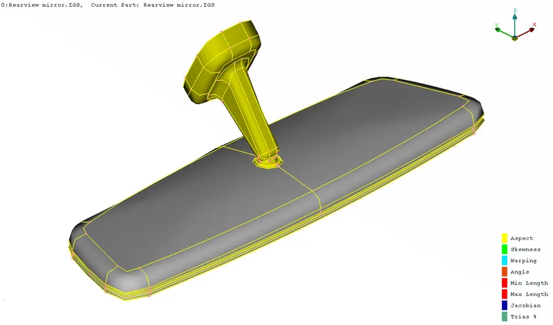
2) Geometry Cleanup
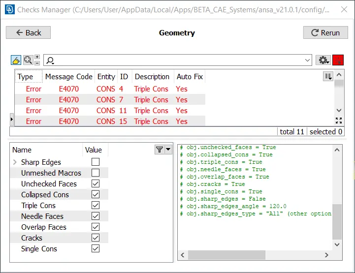
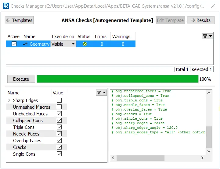
Before meshing the model, it needs to be ensured that the model surface is perfect and free from errors like free edges, cracks, overlap faces, distorted faces, needle faces, etc. The geometry check is done using the Checks Manager available under, Tools>Checks>Geometry.
ANSA provides an option to automatically rectify the errors. This is done by, selecting all the errors>rigiht click>Fix. If any errors persist then they can be fixed manually.
On the model, if any lines are too close to each other or if the distance between the lines is less than the minimum element length, then one of the lines needs to be removed. Otherwise, on meshing, elements that fail the minimum element length criteria will be created between the closely spaced lines.
3) Shell Meshing
For performing tetra meshing, the surfaces of the component have to be initially meshed with Tria elements.
The given quality criterias need to be specified using the criteria file editor before meshing the model.
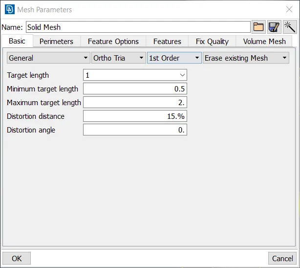
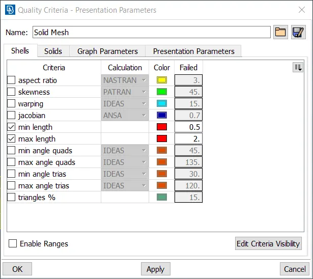
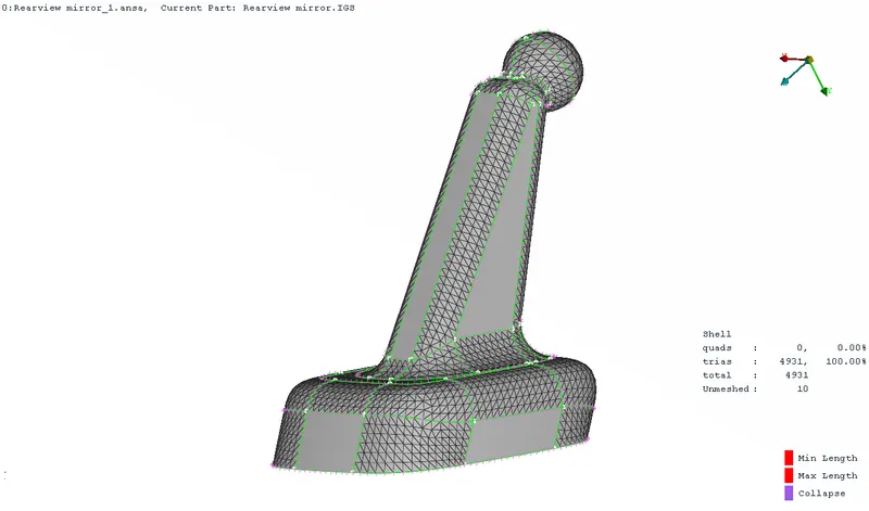
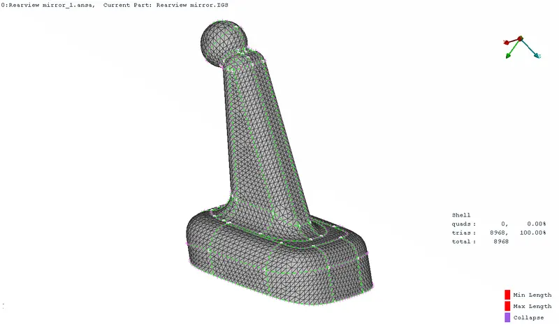
Once the quality criteria’s are set, meshing is performed with a target element size of 1 mm.The meshing is performed using the ‘Spot Mesh’ option under ‘Mesh Generation’. This function automatically meshes Macro and FE shell mesh areas using a special meshing method.
The curved surfaces are meshed using ‘Ortho Tria’ elements and the flat surfaces are meshed using normal ‘Tria’ elements. This is done because Ortho Trias capture the curved surfaces more accurately. But, it is not advisable to mesh the entire model with Ortho Trias as they take more computational time than normal Trias. Hence, only curved surfaces are meshed using Ortho Trias.
4) Ensuring quality of elements generated
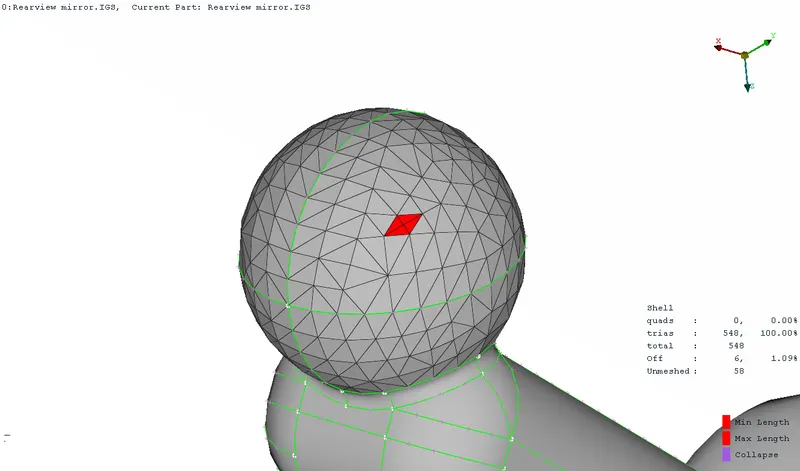
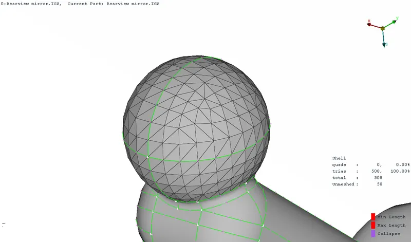
Check if any elements are failing for any of the given quality criteria’s. If any element is found to be failing the given quality criteria then the required cleanup is done to correct them.
The ‘Reconstruct’ option under ‘Shell Mesh’ can be used to improve the mesh. It examines a given mesh and performs re-meshing to correct problematic areas and optimize the overall quality of the mesh according to the mesh parameters.
5) Volume Meshing
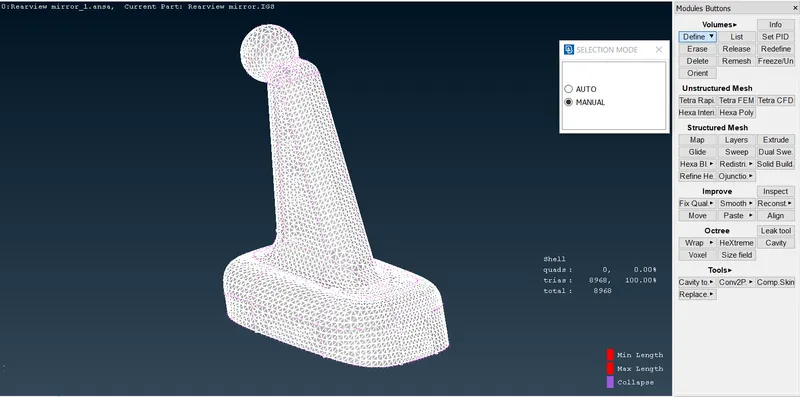
After performing 2D meshing on the component with Tria elements, to perform 3D tetra meshing on the components, each of the component has to be defined as an enclosed volume. The volume can be defined using the ‘Define’ option present under Volume Mesh>Volumes.
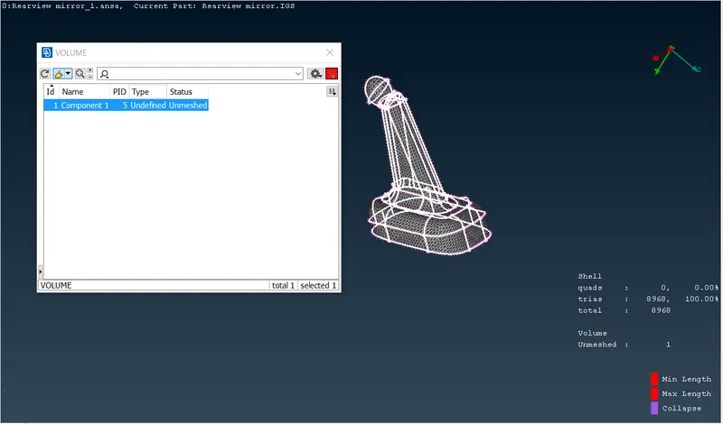
The defined volumes can be viewed under the ‘Volumes>List’ option.
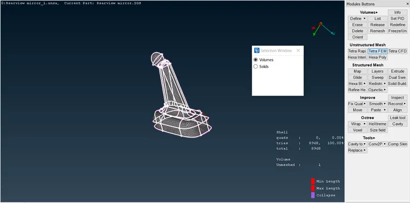
The created volumes can be meshed with tetra elements using either the ‘Tetra Rapid’ or ‘Tetra FEM’ options under Unstructured Mesh.
Volume Mesh>Unstructured Mesh>Tetra Rapid/Tetra FEM
6) Ensuring quality of tetra elements generated
Check if any tetra elements are failing for Tet Collapse. If any element is found to be failing for Tet Collapse then it can be corrected automatically using the Fix Quality option under ‘Improve’ or it can be corrected manually by using the ‘MV Free’ option under ‘Grids’. But using the automatic option may lead to kinks or raised edges on the surface of the component, hence, manual correction is preferred.
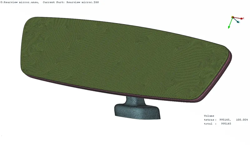
FINAL MESHED MODEL IMAGE:
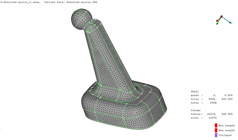
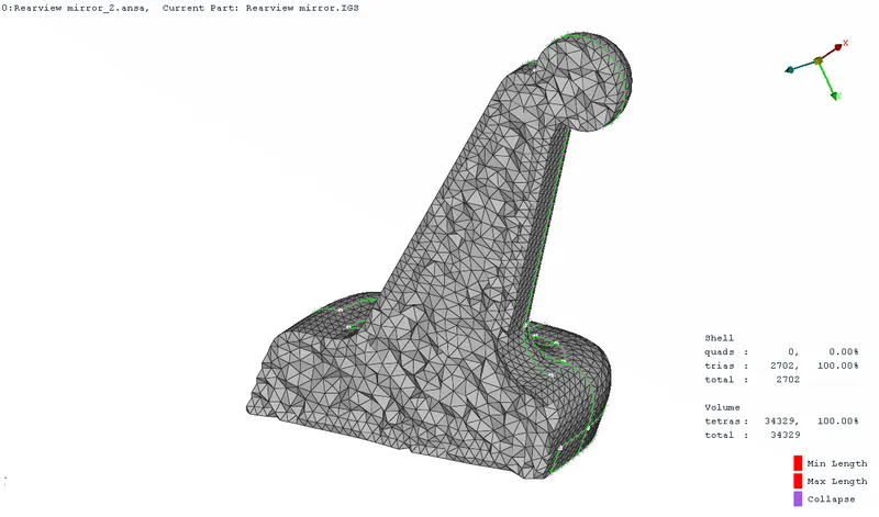
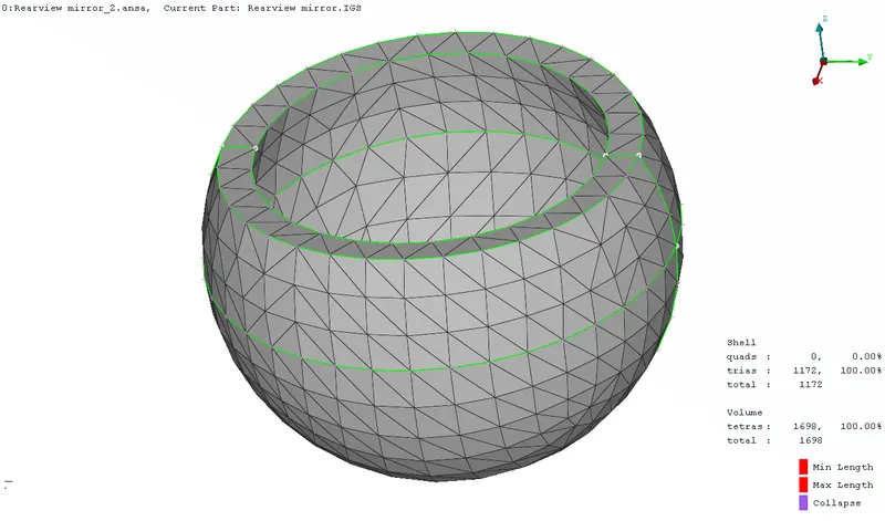
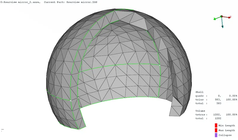
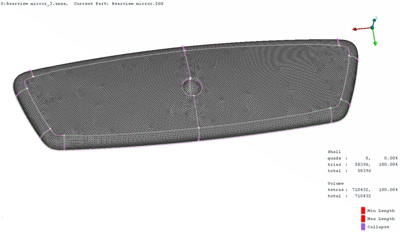
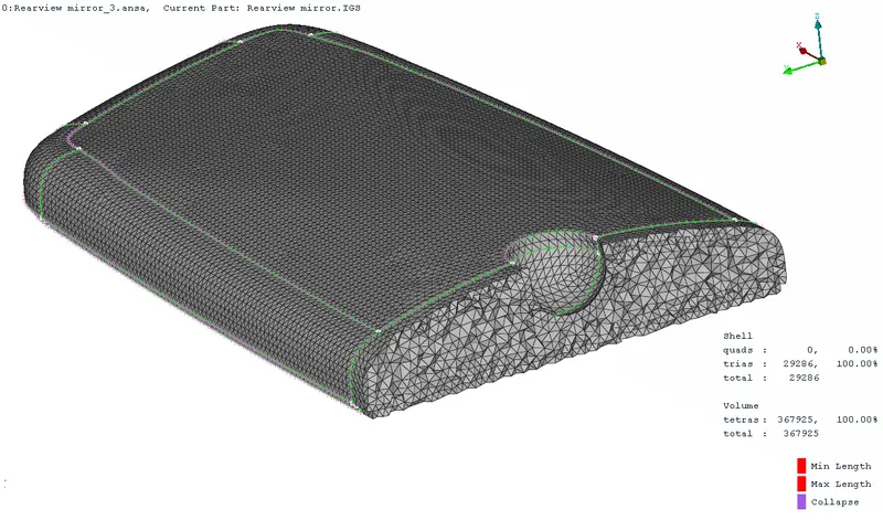
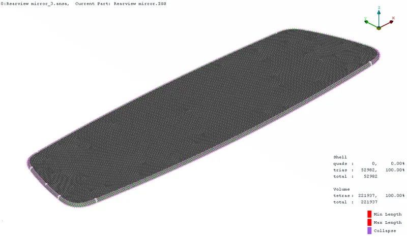
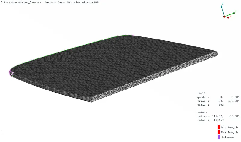
Full model:
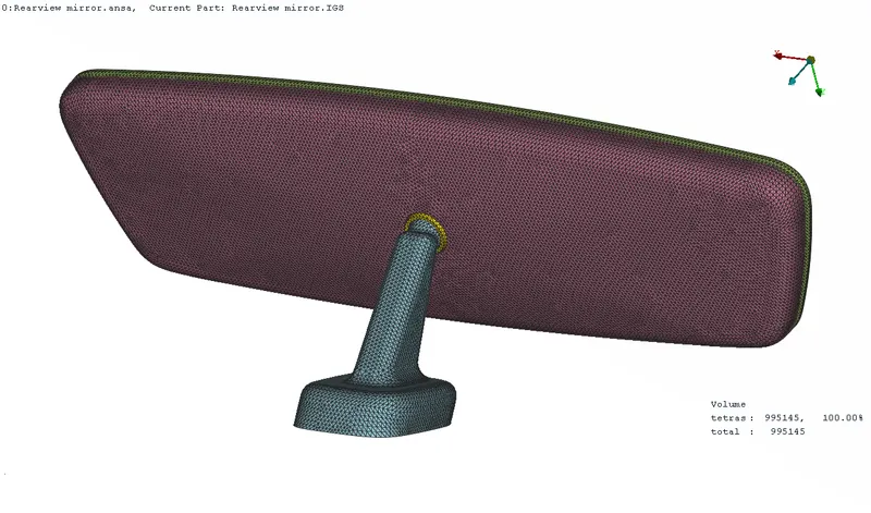
LEARNING OUTCOMES:
Learned how to define a volume and perform Solid Meshing on a component by following the given quality criterias.
Gained understanding on how to obtain good quality tetra mesh by removing errors such as Tet Collapse.
CONCLUSION:
The surfaces of the given component were initially meshed with Tria elements and then Tetra meshing was performed on the defined volumes of the component by following the given quality criteria’s.