Deploying connections between components in frame assembly welding model
AIM : To attach the various parts by deploying the connections to the given component as per given connection details.
CONNECTORS :
In the previous challenges we have been doing the meshing operation on the midsurface we extracted for sheet metal components like car hood for example. In this challenge we have frame assembly welding model,in this challenge we not only perform meshing, but also we make connections between component to component with connector elements like weld and bolted connections. Basically connectors are geometrical entities that define connections between components,elements,nodes.Connectors allow for easy and rapid Creation of FE welds, bolts, adhesives, etc.
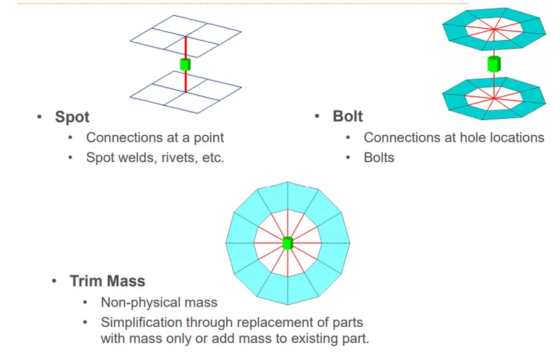
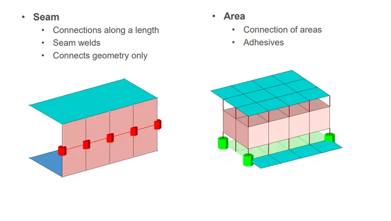
we have various type of 1d connector elements in hypermesh.we take a brief look at what they are.
PROCEDURE :
we first import the model which is in .hm file format.
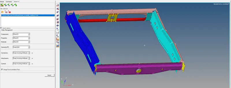
after importing, we have changed the view from "by part" to "by component" to see the different components with different colour representation so that it will be easy for us to identify the particular component while giving connections.
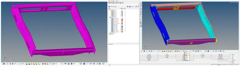
now we proceed with meshing operation with mixed type(quad+tria) element with element size as 5.after meshing all the surfaces we will manage trias,quality crieria and mesh flow with the same process we followed for hood model.
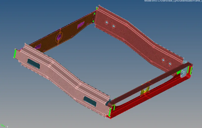
after meshing we proceed with creating connections between components.
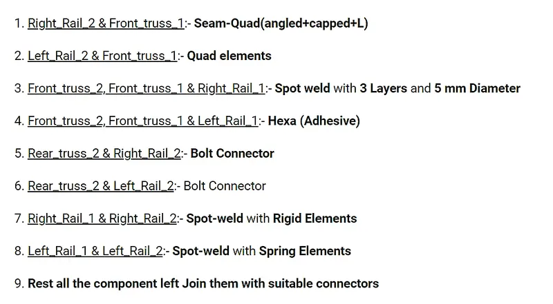
1. Right_Rail_2 & Front_truss_1:- Seam-Quad(angled+capped+L)
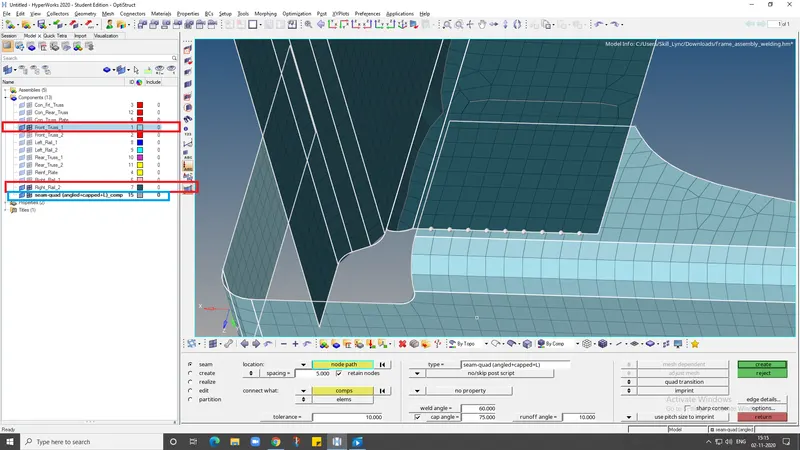
In this step we have to hide all the other components except the one which we are going to work on for suppose in this step we will keep right rail 2 and front truss 1 and hide all other components since those are the two which we have to connect with Seam-Quad(angled+capped+L) connection. since the seam weld connector is created at free ends of the components we have to select the node list to deploy connections on those nodes. to create seam weld connection we go to 2d-connectors-seam-location as node path and we select the nodes along the line where weld has to be created. after creating the nodes we choose seam weld type:seam-quad (angled + capped + L) and give spacing as 5 mm.since we are connecting the components we select component option under "select what" tab and we give tolerance value of 10 with weld and cap angle as 60 and 75 and then we select the create option, the below images shows the seam weld connection that created between the two adjacent component
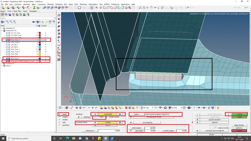
here we can see from above picture that the connection is properly realized. A realized connector will be considered as the successful representation of a CAD model in preprocessing and the connecting parts can be considered as connected. It is possible that sometimes the connector may not be realized.the reasons might be because of mismatch of nodes count between two components or it might be because of improper tolerance value also.
Options to be changed to Realize the connectors:
- “Spacing” value defines the space between each node of the weld element, which should be equal to the Target element size, this will ease the weld element to be created between the components.
- Only entities within this tolerance can be taken into account for the link detection and the final realization. If the connection entities are away from the search tolerance, seam weld may not get realized.
2. Left_Rail_2 & Front_truss_1:- Quad elements
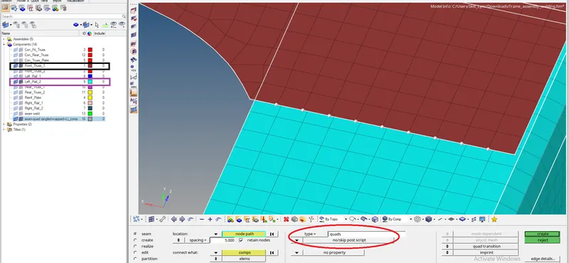
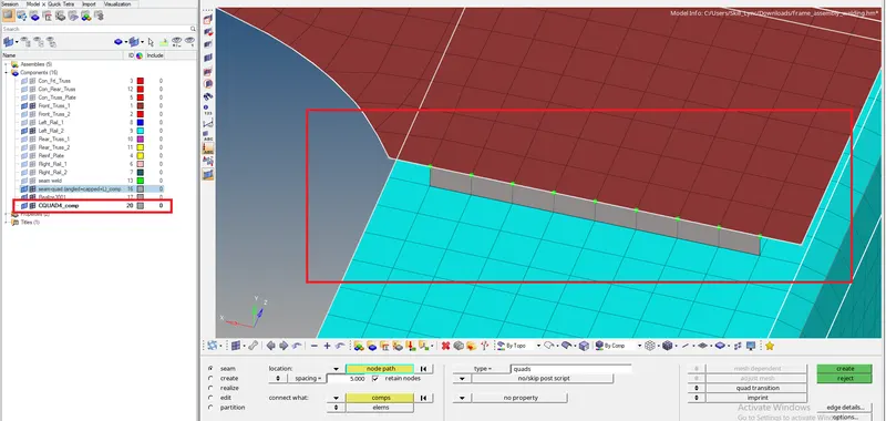
for creating quad connection between left rail 2 and front truss 1 we go to 2d-connectors-seam-location:nodelist-select the nodes along the path where we want to weld then select type:quad with spacing:5mm and select the two components which needs to be joined then we specify tolerance value of 10 and then by clicking on create option it will create the connection.
3. Front_truss_2, Front_truss_1 & Right_Rail_1:- Spot weld with 3 Layers and 5 mm Diameter
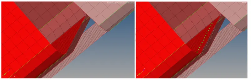
To create a spot weld connection we go to 2d-connectors-spot-location:nodelist then we select the node path where we want to deploy connection and select type:weld with diameter:5mm and then we select the components which are to be joined with tolerance value 10 then after clicking on create will deploy the connection.
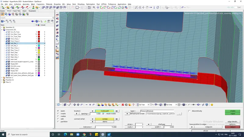
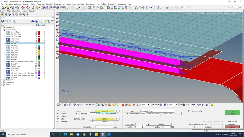
4. Front_truss_2, Front_truss_1 & Left_Rail_1:- Hexa (Adhesive)
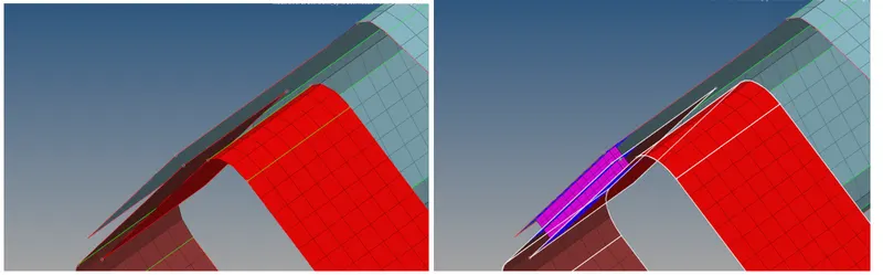
Select 1D/2D → Connectors → Seam option.Now select the location, where the Weld has to be created, by clicking the “node list”.Tick the checkbox of “retain nodes” option, to retain the position of the nodes, while creating and realizing a connector.Specify the “spacing” value and select the “comps” option under “connect what”, in order to create the weld between those two components.Specify the “tolerance” value, based on the distance between the two components.Select the type as “hexa (adhesive)”.Click on the “create” button, to create the seam weld.After completion of the seam- Hexa adhesive, the components will be connected as shown
5. Rear_truss_2 & Right_Rail_2,Rear_truss_2 & Left_Rail_2 :- Bolt Connector
in order to create a Bolt connection, if we had hole present in the components, we have to locate a centre node as shown below
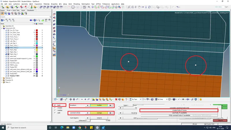
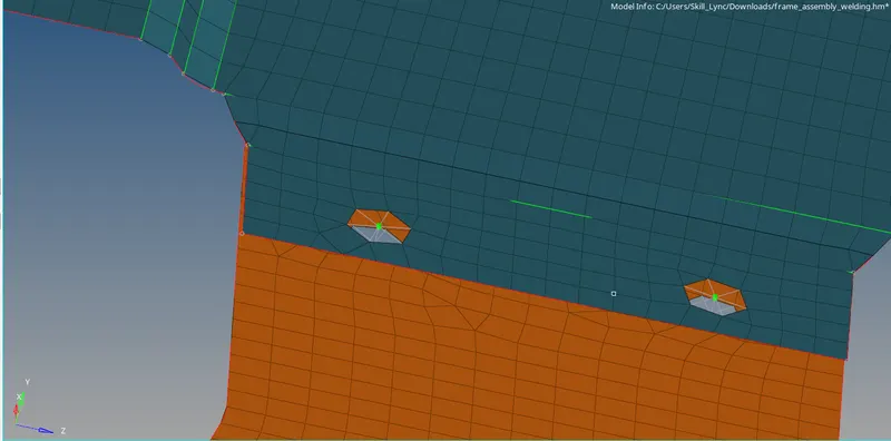
Now click on the 1D/2D → Connectors → Bolt option.Under “location”, select the node, which we created already to establish the bolt connection.Then select the “comps” option under “connect what”, in order to create the weld between those two components.Select the number of layers to be welded, under “num layers” option.Specify the “tolerance” value, based on the distance between the two components.Select the type as “bolt (general)” then Click on the “create” button, to create the seam weld.After completion of the Bolt connection, the components will be connected as shown.
6. Right_Rail_1 & Right_Rail_2:- Spot-weld with Rigid Elements
To create spot weld connection with rigid elements go to 1d-spotweld-using nodes-select the nodes along which the weld is to be created and then select type:rigid and then create the element.
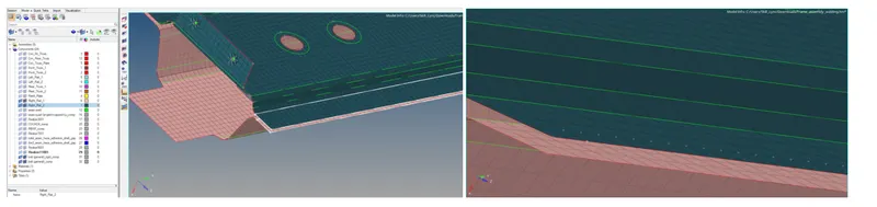
7. Left_Rail_1 & Left_Rail_2:- Spot-weld with Spring Elements
To create spot weld connection with spring elements go to 1d-spotweld-using nodes-select the nodes along which the weld is to be created and then select type:spring then create the element.
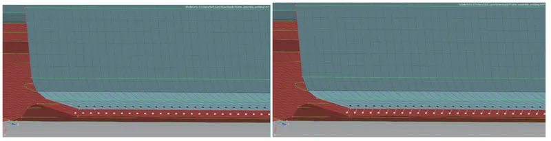
finally, we have connected all the components with proper realization and the rest of the components are connected with suitable connections
RESULT :
1.The given frame assembly model is meshed before creating connection
2.successfully made connections between components as defined in the challenge