Week 8 - Challenge 5 - Core & Cavity Design
Note-
- Tooling axis, Draft analysis, class B and Class C surfaces and final part is already done and explained. So now in this report only parting line, parting surface, core and cavity block is explained.
Title-Core & Cavity Design
Aim- Create the Core and cavity blocks for the switch bezel designed in the earlier challenge.
Objectives –
- To create parting line and parting surface.
- To make core and cavity blocks for switch bezel designed part.
- To publish parting line and parting surface.
Introduction-
- This report demonstrate the design core and cavity blocks for the switch bezel designed part with industry principle like determine and implementation of tooling axis, draft analysis, draft angle, creation of class B and C surfaces, parting line and parting surface.
- Tooling axis, Draft analysis, class B and Class C surfaces and final part is already done and explained. So now in this report only parting line, parting surface, core and cavity block is explained.
- The plastic component is designed with surface and part design technique in CATIA.
Methodology-
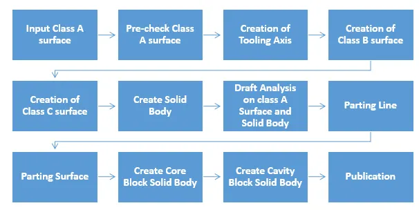
- Tooling axis is a direction in which mould/ core and cavity opens.
- Class A surface- The surface is made by designer and surface design is given to modeler to work on it. It is aesthetic surface and the outer most surface.
- Class B Surface- A surface which is below a certain thickness from class A surface is called as class B surface. It contains engineering aspects of a model.
- Class C Surface- A class C surface that join class- A and Class B surface.
- Draft Analysis-
The Draft Analysis command enables you to detect if the part you drafted will be easily removed. This type of analysis is performed based on color ranges identifying zones on the analyzed element where the deviation from the draft direction at any point, corresponds to specified values.
- Parting Surface-
Generally, in injection molding has two main component- fixed halve (Core) and movable halve (Cavity). During the injection molding process, these two halves are pressed tightly form a sealed hollow to avoid the melt flow leakage and maintain certain holding pressure. The pressed surface called as parting surface. A parting surface is a surface that separates the mold block into two parts – the core and the cavity. Image source.
- Parting surface design principles
Parting surface design directly affects the product quality, ease of construction and operation of the injection mold, the mold design is one of the key factors to success.
- Design parting surface should follow the following principles:
- Design the injection mold structure as simple as possible. Avoid or reduce side parting as much as possible to reduce the complexity of mold making.
- Ease of de-molding. As far as possible, for instance, the plastic parts should stay in fixed halve of the injection mold and ejected by ejection system, avoid side de-molding action.
- Ensure the dimensional accuracy of the molded parts. Try to make the parts with similar dimensional accuracy requirements in the same module to reduce manufacturing and assembly errors.
- Ensure appearance requirement of the molded parts. Flash or mismatch occurs usually on parting surface, so the parting surface should not be designed on any high quality requirement surfaces.
- Ensure adequate venting. If possible, parting surface should be place at the end of the mold flow. This is going to be a good advantage of filling and venting.
- Parting Line-
A ‘parting line’ is the line of separation on the plastic part where the two halves of the plastic injection mold meet. The line actually indicates the parting ‘plane’ that passes through the part. Within more basic plastic part design plans this plane can be a simple, flat surface, but it is often a complex form that traces the perimeter of the part around the various features that make up the part’s outer ‘silhouette’. Part lines can also occur where any two pieces of a mold meet. This can include side action pins, tool inserts and shutoffs. Parting lines cannot be avoided; every part has them. Keep in mind when considering plastic part design that the melt will always flow towards the parting line because it is the easiest place for the displaced air to escape, or ‘vent’.
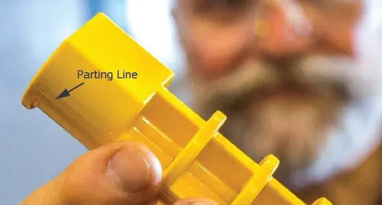
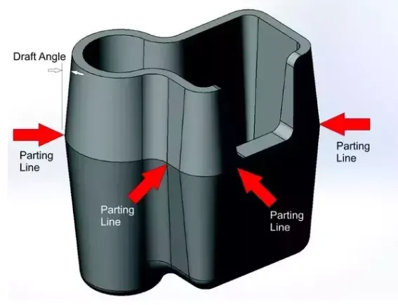
Fig. 1 Parting Line
- Core and Cavity-
The injection molding process uses molds, typically made of steel or aluminum, as the custom tooling. The mold has many components, but can be split into two halves. Each half is attached inside the injection molding machine and the rear half is allowed to slide so that the mold can be opened and closed along the mold's parting line. The two main components of the mold are the mold core and the mold cavity. When the mold is closed, the space between the mold core and the mold cavity forms the part cavity, that will be filled with molten plastic to create the desired part. Multiple-cavity molds are sometimes used, in which the two mold halves form several identical part cavities.
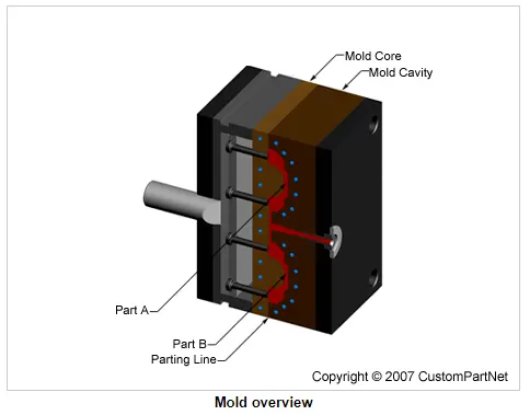
Fig.2 Mold used in injection molding
Important point to consider while designing-
- To create plastic part there are two major components – core and cavity are required. The core is the male part which forms the internal shape of molding. The cavity is the female part which forms external shape of molding.
- The proper (Minimum 3° ) draft angle should be given to the part so that part can removed/ eject easily from mold.
- Draft angle should be given to the class C surface for easy ejection. If draft angle is 0° then there will be friction occurs in the core and cavity.
- Analyze and identify tooling axis proper for draft analysis so that we can avoid side core and save the manufacturing cost of part.
- The parting line is the line which split the mold into two halves- core and cavity. So that parting line should be always in the class B surface so that we cannot see the parting line.
- Part should have uniform thickness all over.
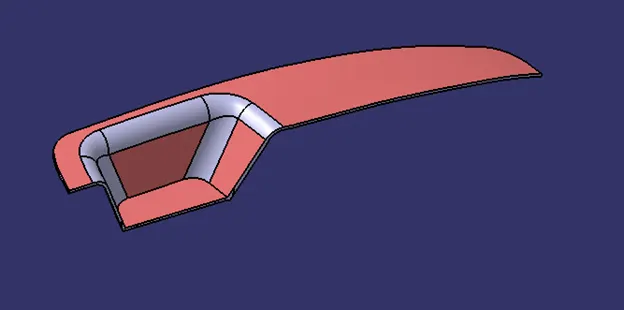
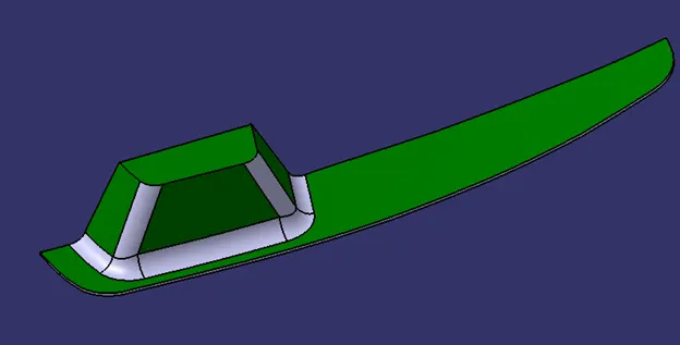
Fig. 3 Core and Cavity side
From above fig. 3 we can see that below outer side- green in color is called as cavity and inner side- pink color is called as core.
- Creation of parting line and surface-
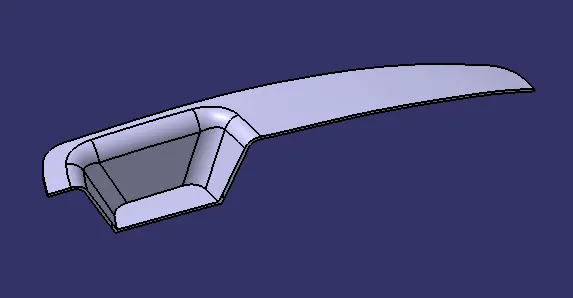
Fig.4 Given switch bezel part
- Parting Line-
As we know that parting line is the line where parting surface and part meets or core half and cavity half meets between the parting surface and part.
To create parting line, we have to take intersection of class B surface and joined class A +C surface together. So we will get parting line which clear splitting line between core and cavity.
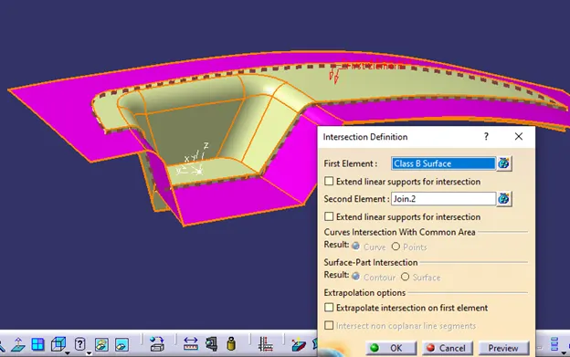
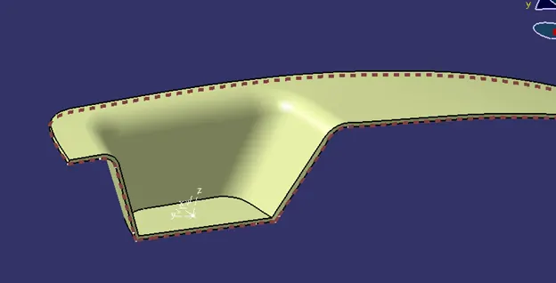
- Parting Surface-
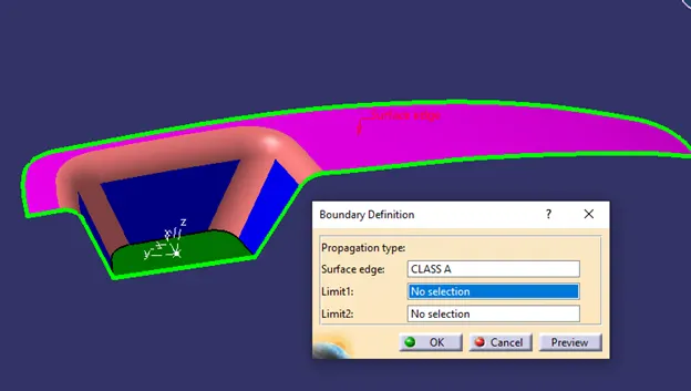
- To create parting surface, first of all extract the boundary of class A surface.
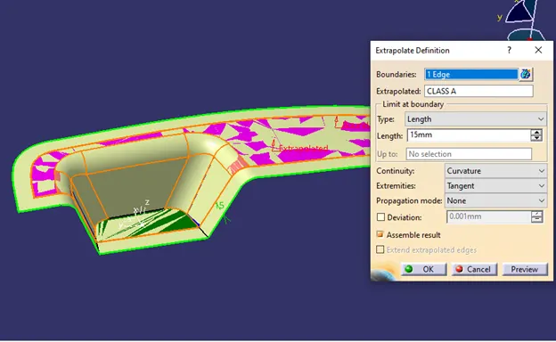
- Extrapolate the extracted boundary of class A surface at distance 15mm.
- Trim the extrapolated surface and class C surface together.
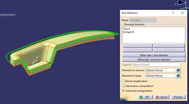
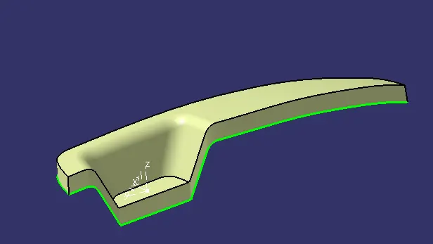
- Trim the last trimmed surface and class B surface together and we will get parting surface with part area.
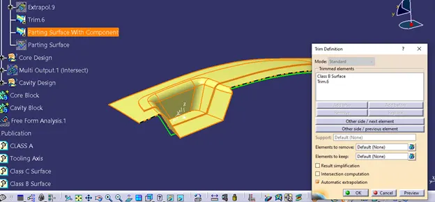
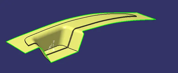
- Split the parting surface with part area and parting line and we get final parting surface which is shown in blue color.
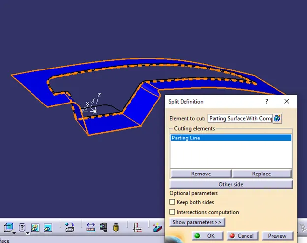
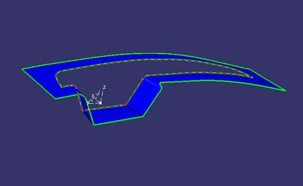
- Design of core and cavity block-
- Core Block-
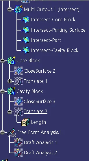
- We have parting surface between core and cavity i.e parting surface where core and cavity is going to split.
- Now we will create rectangular block using positioned sketch on XY plane so that we can cut the parting surface.
- While creating rectangular sketch, make sure that boundaries of sketch should be inside the parting surface.
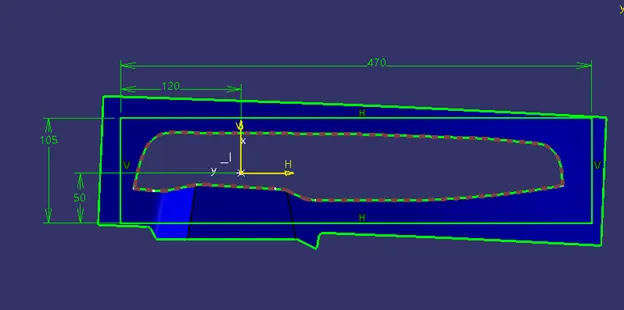
- Extrude the sketch along tooling axis from both side.
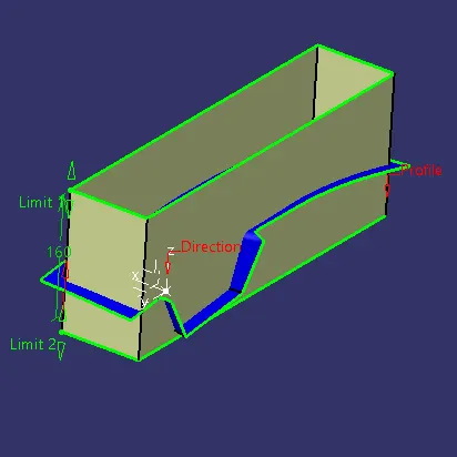
- Trim the extruded block surface and parting surface together.
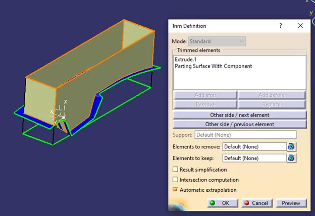
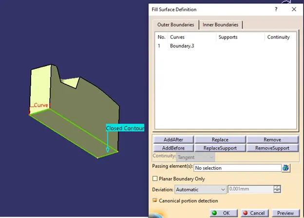
- Fill the trimmed surface by creation boundary option and join all surfaces together. Make sure that no boundary is present.
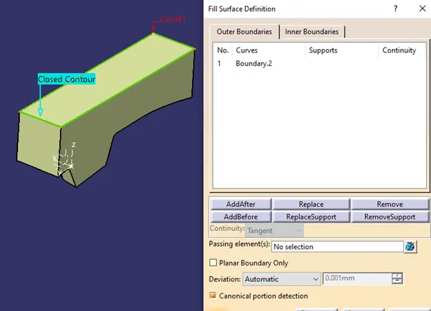
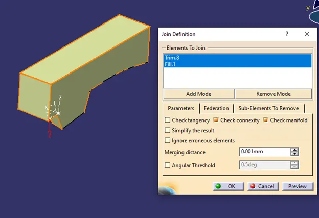
- Convert core block surfaces in to body by sing closed surface command.
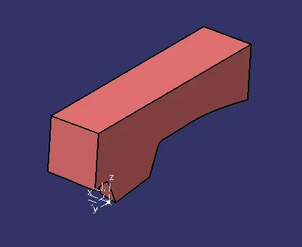
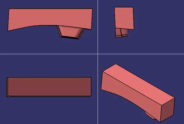
- Cavity Design-
- Follow same procedure as above mention for core block design. First extrude the sketch along tooling axis and then trim with class B surface.
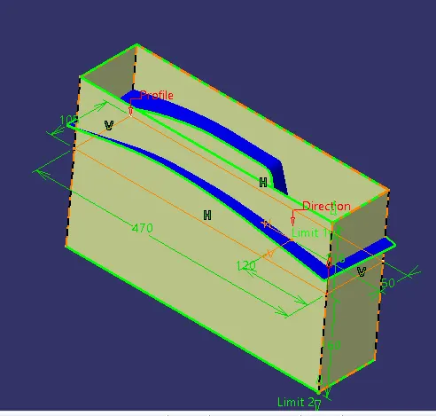
- Trim the extruded surface and class B surface together.
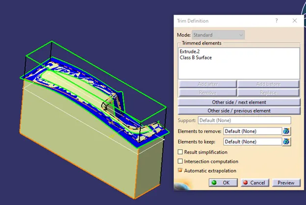
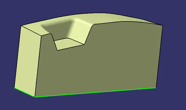
- Fill the open boundary of trimmed surface and joined all the surfaces together.
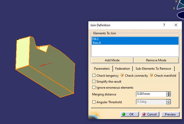
- Convert cavity block surfaces into solid body using closed body option.
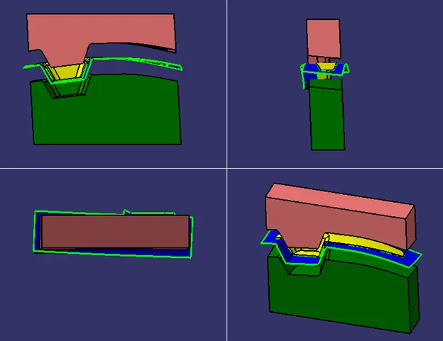
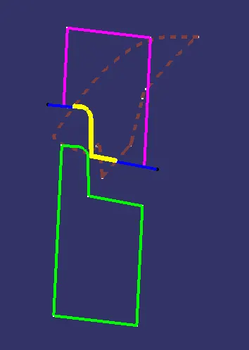
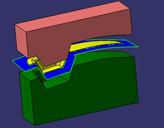
Here we have taken intersection between X plane with parting line, parting surface, component and core block. We can see in below fig. parting line shown is brown color, parting surface is shown in blue color which split core and cavity, component is shown in yellow color, cavity block shown in green color and core block is shown in pink color.
- Now we will translate the core and cavity block for easy understanding of core, cavity, parting line, parting surface and part.
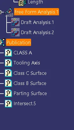
- Publication-
- This feature is used to make easy access of published component (Surface or Sketch).
- Here parting line and surface, core and cavity block are published.
- Path- Tools > Publication > Select entity (Surface/ Sketch/Body)
- Conclusion-
- The parting line and parting surface identified and created for switch bezel part.
- The core block and cavity blocks are created for part in CATIA V5.
- The solid closed body model is made using core and cavity blocks.
- The core and cavity blocks are translated for easy understanding.
- The parting line, surface, core and cavity blocks are published.
- Screenshots of the Draft analysis report for both the switch bezel plastic component
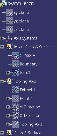
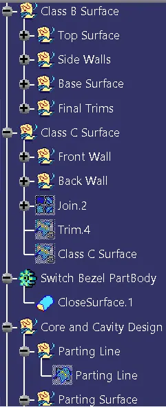
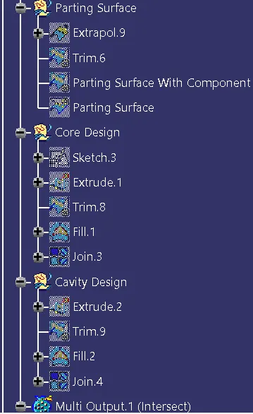
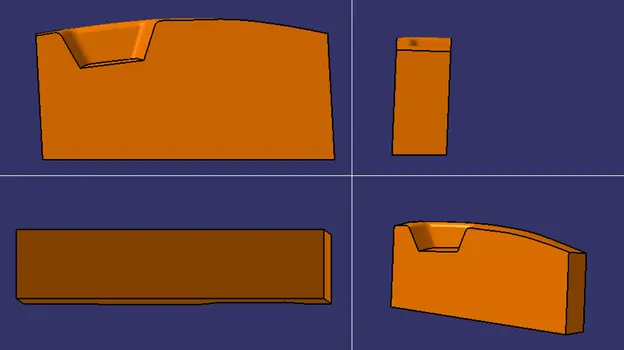
- Screenshots of the core and cavity blocks in various orientations (Isometric, Front, Side, and Top View)