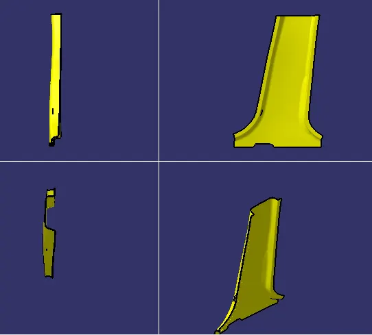
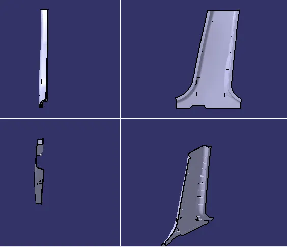
Week 9 - Project - Master Section Development
Title- Design and development of the B-pillar through master section development (Interior Trim)
- Aim- To design and develop B-pillar from given class A surface and master section into a functional product design following the OEM design standards using CATIA V5 surface and part workbench following injection molding principles.
Given Data-
- A surface
- Master section
- Distance between rib should be 50 mm.
- Objectives-
- To create a tooling axis and following design rules.
- To create class B and C surface using class A surface as an input
- To create flange from master section
- To create attachment features for class B surface using master sections
- Abstract-
The report details about the design life cycle in automotive industry with a practical working model of B pillar cover on the B pillar of car interior. The report explains the steps followed in creating the tooling axis, detailed methods in creating B surface, class C surface and to closed body. The attachment features creation is also reported by following the design guidelines and finally analysis of draft to prevent the failure and improve the feasibility of manufacturing the part in plastic injection molding.
- Introduction-
- Pillar-
The body of an automobile is made of a structure that is just the same as that of a house. It has similar components, which include the roof, the pillars, and the floor. The car pillar in the vehicle stands in the near-vertical position, which supports the vehicle’s roof. However, the A-pillar and the D pillar stand inclined in some vehicles for aerodynamic reasons.
Furthermore, the manufacturers identify the car pillars from the side while moving from front to rear of the vehicle. They name the car pillars as the A-pillar, B pillar, C pillar, and D pillar. Sometimes, the vehicle designers also refer to the car pillars as 'posts.'
The naming system adopted for the pillars possibly originates from their shapes as seen from sides shown in Fig.1. The A-pillar resembles the shape of the alphabet “A”. The other pillars resemble “B,” “C,” and “D” letters, respectively.
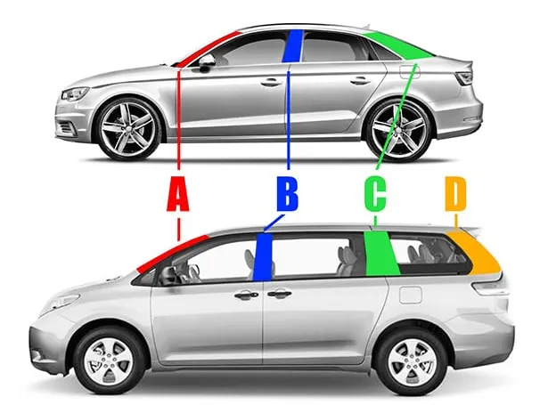
Fig.1 pillars in automobile from side
- B Pillar:
Furthermore, B Pillar is the most complex component/structure of the vehicle body. This is because the front door closes on the B pillar while the rear door hinges onto it. The B pillar or the center pillar in vehicles is made of steel. It is welded to roof panel on top and the vehicle’s floor pan at the bottom. This pillar provides structural support to the vehicle’s roof.
Manufacturers skip the B pillar while naming other pillars. Hence, some vehicles do not have a B Pillar. The carmakers term those cars as 'Hardtops.' Instead, the vehicle specification shows the rearmost pillar as the C pillar. The manufacturers offer the Hardtops in nearly all four-door body styles. They include sedans, coupes, and wagons/MPVs. The cars without B pillars increase passenger’s visibility. However, they have limited structural support and strength. General Motors later started providing B pillars in Hardtops. Thus, it created a new vehicle body type and thereby broadened the definition of Hardtops.
The vertical roof support structure located between the front and rear doors on a typical vehicle. It corresponds with the A pillar located on either side of the windshield at the front of the car and the C pillar which sits on either side of the rear window on a typical sedan. On SUVs, minivans and wagons with extended cargo areas, the C Pillar is the vertical structure behind the rear door while the vertical supports at the rear of the vehicle are called D pillars.
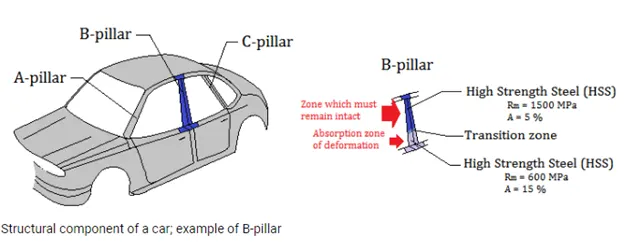
Fig.2 B -Pillar
- Master Section-
Master sections are the guides for design requirements which shapes the component after technical styling after technical styling of class A surface. The body frame is mainly composed of floor longitudinal beams, upper side beams, door side beams and front cover, the rear beam, A-pillar , B-pillar, C-pillar and other load- bearing beam structure are composed.
Master sections are parameterized model of the vehicle body that outlines the guide for NPD team.
In this report B pillar cover creation with detailed procedure of surface development and attachment features are covered.
- Overview Design life cycle automotive Industry-
The stages of design life cycle are-
- Concept Sketches- It is a rough idea of free hand sketch obtained through styling team and will be used to prepare the model.
- Class A Creation- After finalizing the concept the sketches are usually worked in software’s such as auto-desk alias to create class A surface.
- Clay Modelling- The class A surface is concurrently worked by clay modelers to brainstorm and benchmark the styling of the product and later the concept is validated by bringing up a rough clay model and then it is passed on the design team for the preparation of NPD cad.
- NPD CAD- Here development of surfaces to parts in CAD kick off and design engineer involvement is necessary. The procedure followed in creation of plastic new product design are-
- Pre-check for any defects or irregularities in the class A surface.
- Create a tooling axis
- Perform the draft analysis on class A surface
- Create class B surface form given class A surface
- Understand the master-section
- Make the flanges on both side to make the aesthetic model complete.
- Create C surface from class A and B surface with flanges.
- Make a surface model by trimming surface A, B and C together.
- Close the model
- Make as B side features
- Run draft analysis on the final model and make a report.
Tooling axis- It is a direction in which mould/ core and cavity opens
Class A surface- Styling surface that is visible to the customer and gives as aesthetic look for the model designed. It has curvature continuity.
Class B surface- it is secondary surface where you can sometimes include all engineering features such as dog house, locators, ribs, flanges, etc. This is direct offset of the class A surface which gives thickness to the component.
Class C surface- This surface is a combination of class A and B surface also they are the backside surface that can have tool marks, flash and other imperfections without hurting appearance, function, etc.
Automotive trims ( Interior and Exterior)- Trims are the plastic parts installed on the inside and outside of a car. The interior trims are usually used for giving the aesthetic look to the interior of the car. There are various types of trims used in automobiles shown in fig.3.
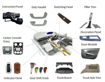
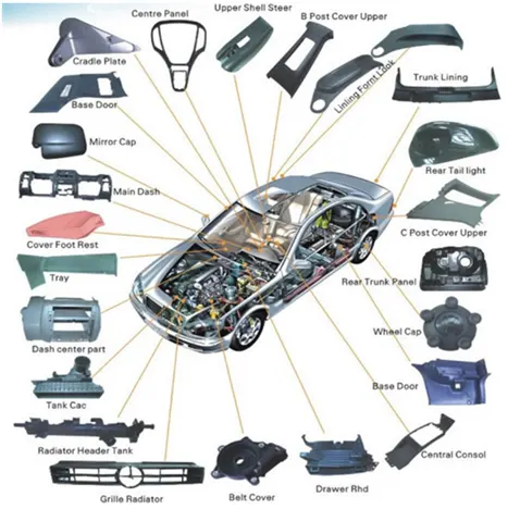
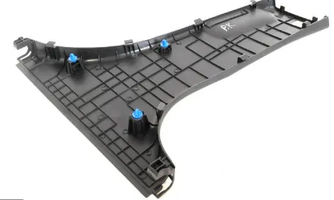
Fig.3 various types of trims
- Methodology for creation of B-pillar in detailed-
Given data shown in fig. 4-
- Master section_1 shown in yellow color
- Master section_2 shown in green color
- Class A surface
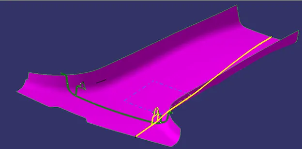
Fig.4 Given data
Step 1-Precheck
To ensure that class A surface is properly joined or there is no discontinuity in the model. This can be checked by using two options, Join or Boundary feature in CATIA. Check for any opening in the given model of door applique by using boundary.
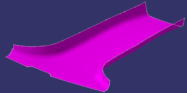
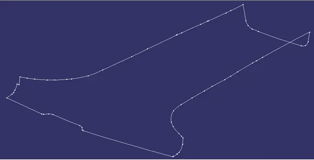
Fig.5 Continue boundary
Step 2- Tooling Axis creation
Tooling axis is a direction in which mould/ core and cavity opens. So analyze the model visually to see which direction is most suitable for tooling axis so next Steps is to create tooling axis.
By providing tooling axis to the class A surface, we can do the draft analysis on the surfaces /component. Draft analysis is performed on component where the ejection of materials happens after the materials is made inside the tool.
Steps followed to create tooling axis-
- Here we have used master section 1 and 2. As we can see that at the intersection of master sections, there is a 4 way locator on dog house. The side of the 4 way locator was used to create tooling axis.
- Create a point from which tooling axis will passed, extract the bottom line of 4 way locator and create a point at the middle of the extract.
- All 4 sides of locator are extracted from master section 1 and 2.
- Now two bisecting lines are created from opposite side of locator passing through the created point.
- Then a new bisecting line is created using above mentioned two resulting lines. This is the final tooling axis for the component.
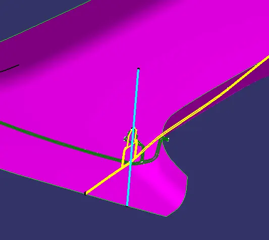
Fig.6 Tooling axis
Step 3-Draft Analysis on class A surface
The plastic product which is drafted to desired nominal angle for feasible clearance and ejection of final part from the mold.
To check the validity of tooling axis draft analysis is performed on class A surface. Draft analysis result shows that the plastic product which is drafted to desired nominal angle for feasible clearance and ejection of final part from the mold.
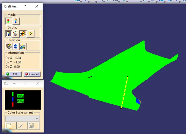
Fig.7 Draft analysis on class A surface
From the draft analysis results fig. 7, it was observed that all the surfaces fulfil the condition of 3° positive draft except one patch as shown above.
Since it is a very small patch with negative draft of minimal value of -0.228°, design of the component is proceeded but this problem will be highlighted to the class A team.
Step 4-Class B Surface creation
Since the given class A surface is a complete styling surface and does not have any defined fillet values or intersection. To get the class B surface, there are two ways-
- Simply the complete class a surface offset at distance 2mm
- Extract flat surface and the work them one by one(Local method)
Fig.8 shows that class b is created by simply offsetting the class A surface at a distance 2mm. Distance is measured from master sections.
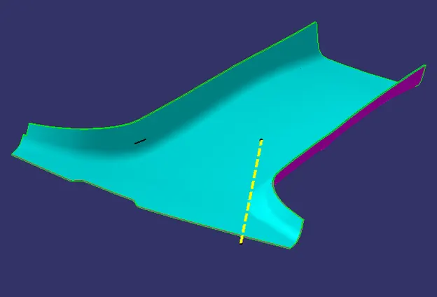
Fig.8 class B surface
Step 5-Flanges creation-
For creation of flange on edge of the class A surface, extract surfaces near the edge and boundary of class A surface shown in fig.9
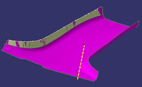
Fig.9 Extracted edge and surface of class a surface
Swept the extracted edges along extracted surfaces using sweep command. A new plan is created on master section_2 with through three point and the intersection of swept surface and plane is taken to observe that if the flange is proper or not w.r.t master section_2. Sweep surface i.e sweep angle should be match with master section_2.
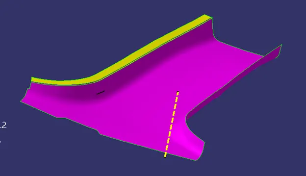
Fig. 10 Flange for class A surface on one side
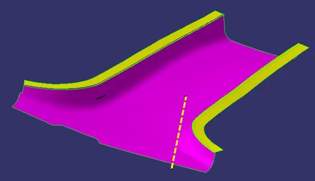
Fig.11 Flanges for class A surface
Similarly above flange is also created at the right edge of class A surface and both the flanges are trimmed with the class A surface to get final output of class A surface with flanges. Fillet of radius 2.5 is applied at the intersection of class A and flanges.
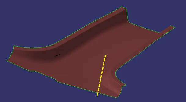
Fig.12 Class A surface with flanges
For creation of class B surface with flange, offset the flanges at a distance 2 mm upward. And then trim offset flanges and class B surface together and apply fillet R4.5mm at intersection of class B surface and flange.
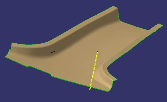
Fig.13 Class B surface with flanges
Step 6- Create class C surface
For creation of class C surface, all edges of the class A with flanges are extracted and concerted into smooth curve. Then they are swept with draft of 3° outeward in the direction of tooling axis.
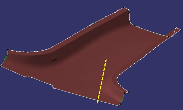
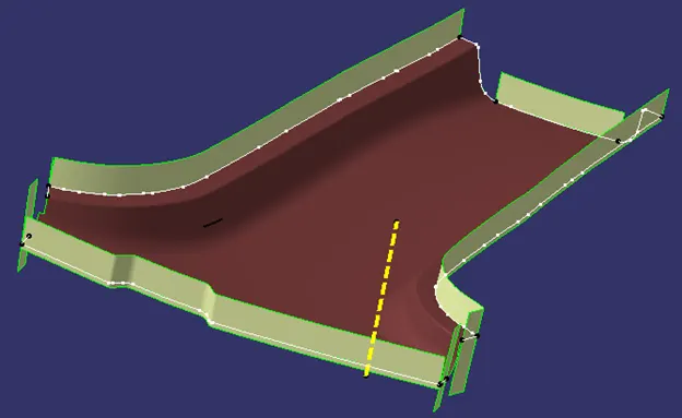
Fig. 14 Edges of class A surface with flanges are swept along tooling axis
While creating class C surface we found that there are some fillets in some areas so need to work on them manually. If the swept surface are not intersection they are extrapolated to the intersection. Then all the swept surfaces and class A surface with flange are trimmed together to get final class C surface.
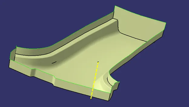
Fig. 15 Class A + C surface
Step 7-Create a surface model
Trimmed class A+C surface and class B surface with flange together and closed volume is formed without open boundary. And this is our surface model.
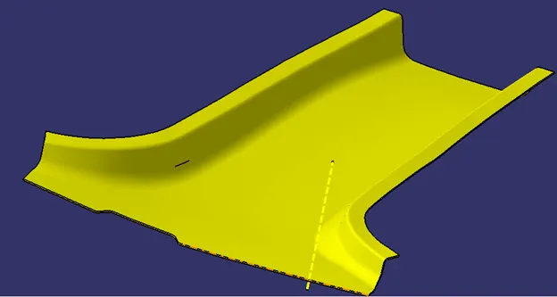
Fig. 16 Class A+B+C surface
Step 8- Create a close body
Closed surface model in converted into solid closed body using part design workbench.
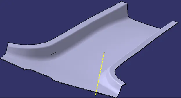
Fig.17 Closed B-pillar body
Step- 9 side features creation-
- Dog House with 4 way locator
Dog house is an engineering featured used on B side to increase the length of screw boss or locators. This allows to have a long attachment feature with better strength and no sink marks.
To create dog house from master section, a positioned sketch is created using plane and point at the place of dog house. In this sketch, the inner profile of the dog house is projected from master section. This profile is extruded in both directions for certain value. Then two lines are extracted from master section and extruded to specify start and end limit of dog house
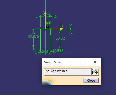
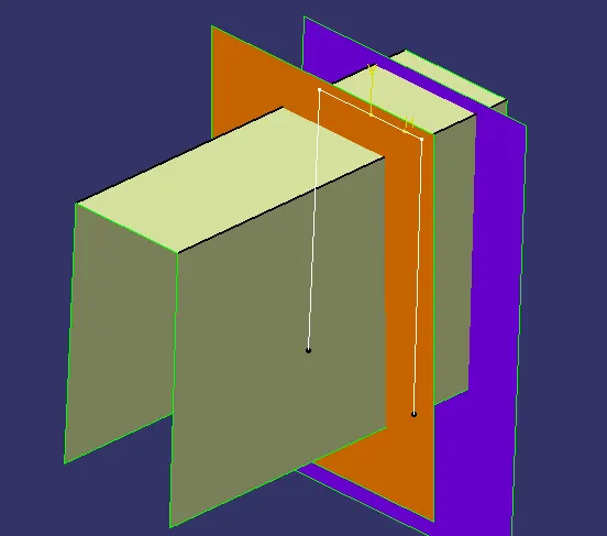
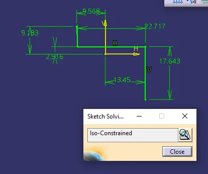
Fig.18 dog house profile extruded with start and end limit surfaces
A line is created in the direction of extrusion. This line will be considered as slider axis.
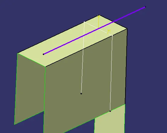
Fig. 19 Lifter axis
The dog house is trimmed with end limit and then thicken outward to 2mm in body design workbench. Finally slit the thicken body by start limit to get open profile of dog house.
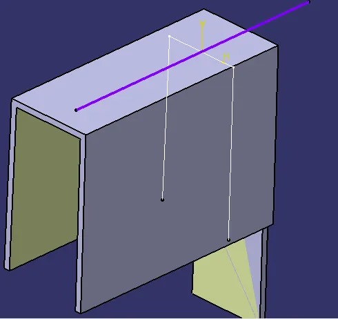
Fig.20 Dog house thicken body
As we know that, to avoid sink mark on class A surface, the bottom of dog house is made 40% of the component thickness as per design guidelines. For that extract class B surfaces and offset at 3mm and inner wall of dog house at 1.2mm. Filler are applied at sharp edges- inner side R.1mm and outer sharp edges R3mm.
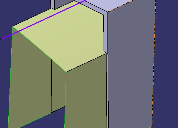
Fig.21 Split surfaces for bottom thickness of dog house
2. 4 Way Locators
A 4 way locators is created on the dog house using master section. For 4 way locator ,a sketch of “+” is created on a new plane which is on top of dog house and extruded with thickness of 1.2mm.
Chamfers and fillets are applied on edges of 4 way locator and faces are drafted with 0.5° along tooling axis. And finally Boolean operation “union trim” is applied on 4 way locator with main body dog house.
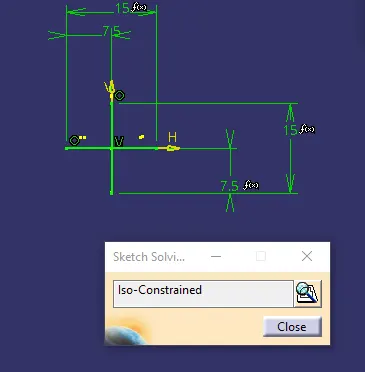
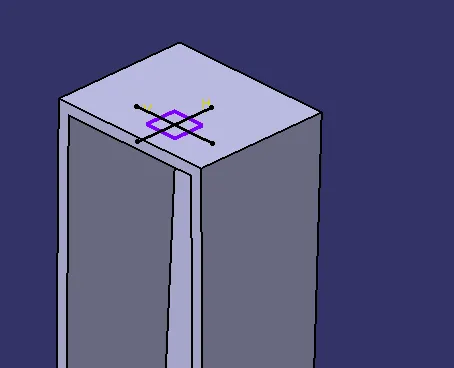
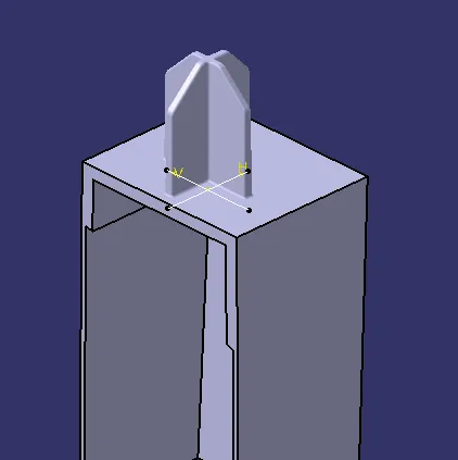
Fig.22 Dog house with 4 way locator creation
The same dog house with locator is copied and pasted with link. Then symmetric body is made on the other side of master section using using at middle of it. Both dog house with 4 way locators are added in main body using union trim.
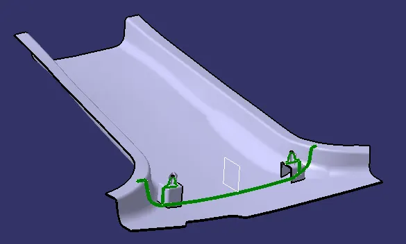
Fig.23 Dog house on both side
3.Rib creation-
Rib are the supporting members which prevents the bending of surface and provide strength to the component.
To start creating ribs, a positioned sketch of lines is created on top plane .This line is extruded and thickened to the values of 0.8mm and all faces are drafted 0.5° along tooling axis. To create multiple ribs, rectangular pattern option is used. It is transferred with created point through the edges of B-pillar at an interval of 55mm.
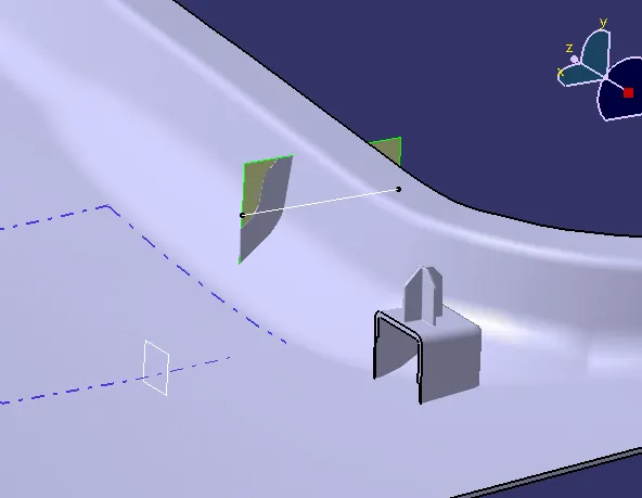
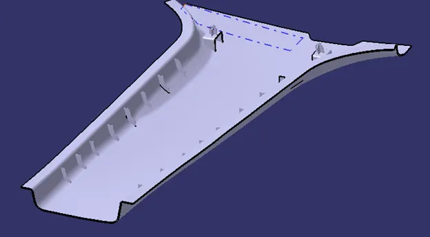
Fig.24 Rib creation
Step 10- Perform draft analysis on final model
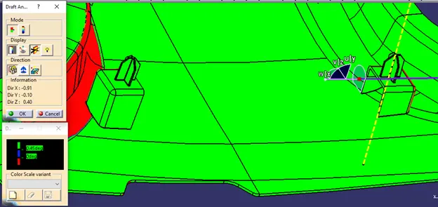
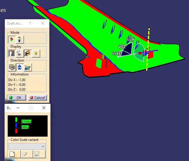
Draft analysis is performed on the final component to check its manufacturing ability. Draft analysis is performed using main tooling f axis and lifter axis.
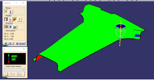
All the faces of a class A surface of component are positive/ have minimum 3° draft except some patch area.
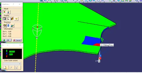
These faces in blue have positive draft but red faces have draft of -0.228 degrees. This will be communicated with the class A surface designer.
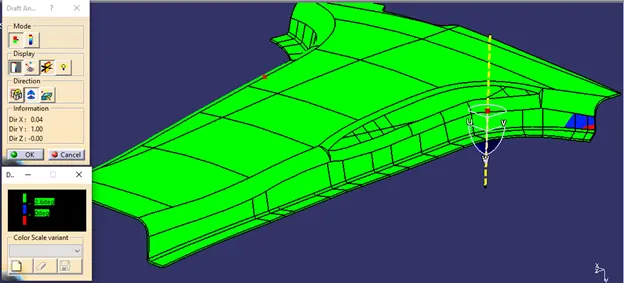
Class C surface is tooled along tooling axis and fulfil the criteria of minimum positive draft.
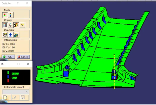
For B side surface, all surfaces including attachment features have minimum draft of 0.5 degrees except the following surface.
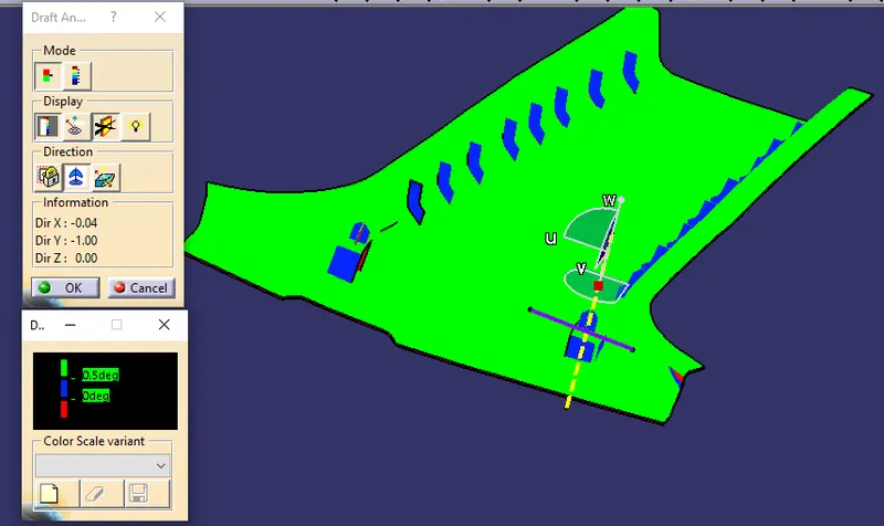

The surfaces in red have negative draft, but can be ignored as it is a very less area and negative draft in class A surfaces is informed to the class A team.
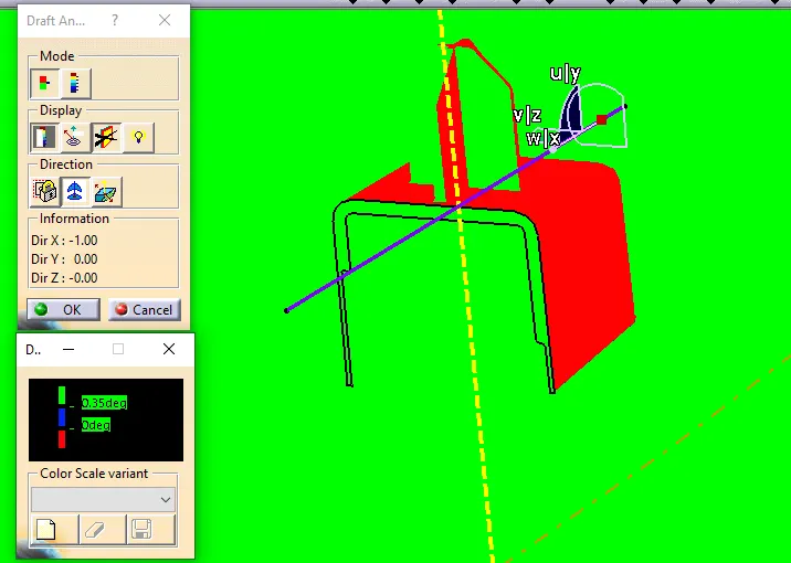
In lifter axis direction, all the internal faces of dog house have minimum draft of 0.5°.
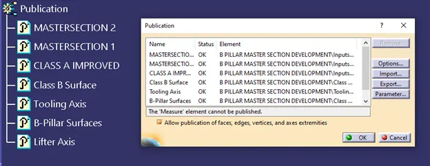
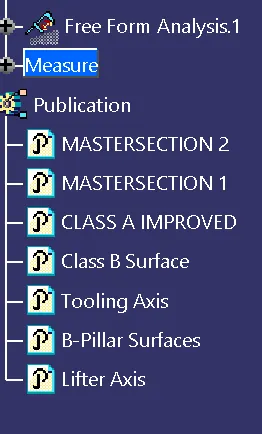
Publication-
Conclusion-
The design of B-pillar trim is completed and from draft analysis it is observed that the design is safe to manufacture except some imperfection which will be communicated to the class A team.
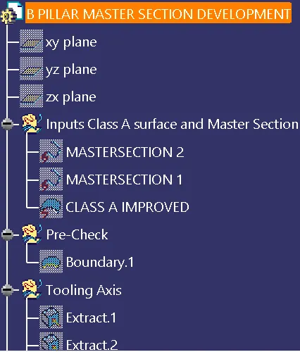
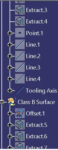
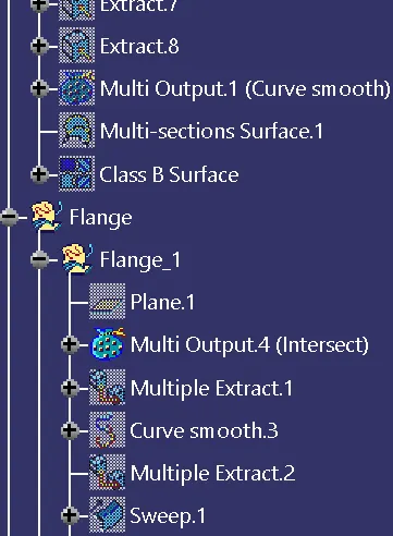
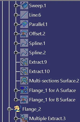
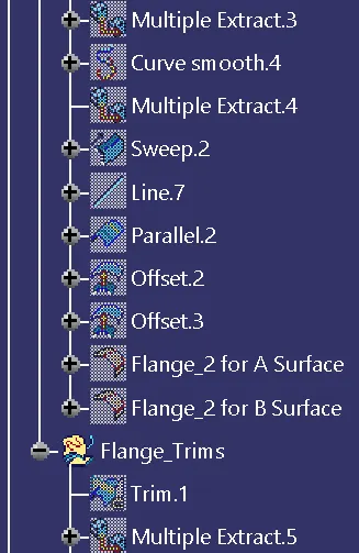
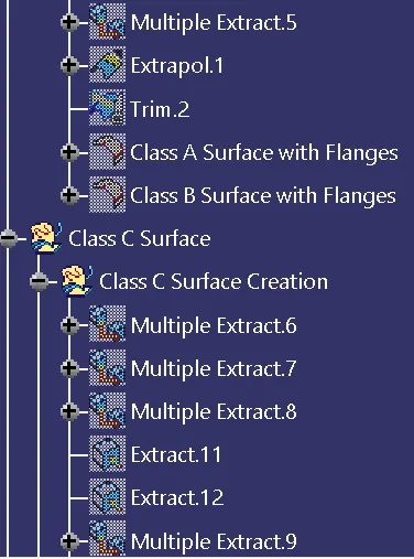
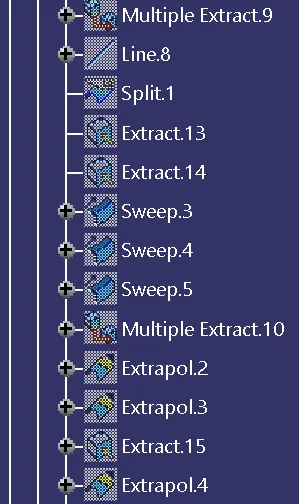
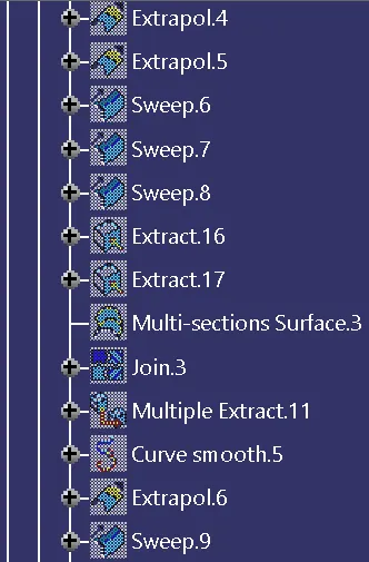
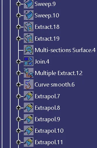
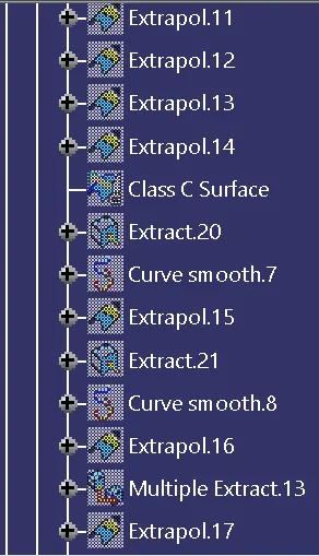
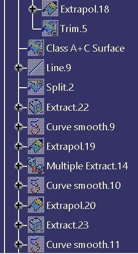
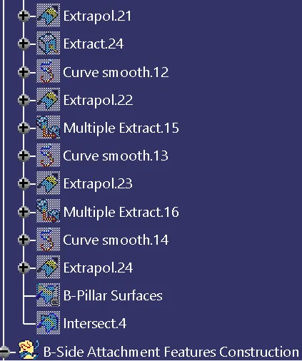
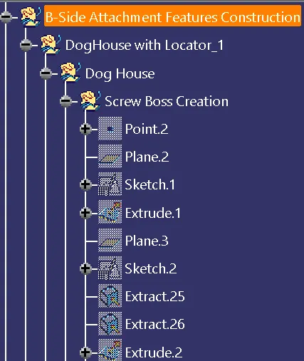
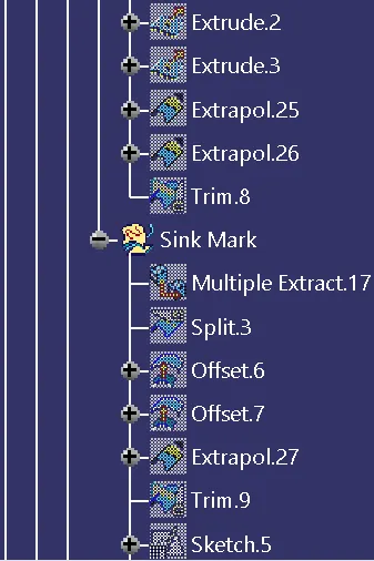
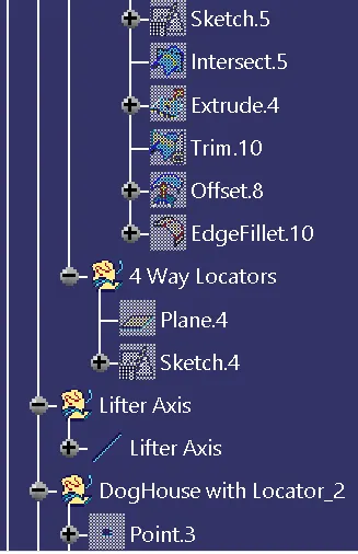
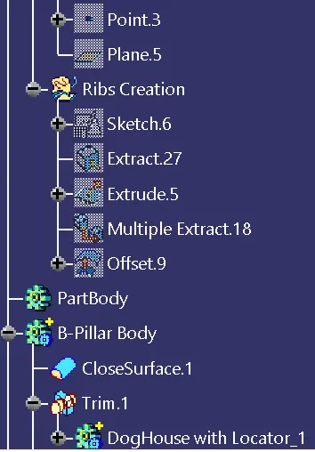
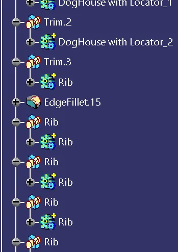
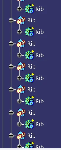
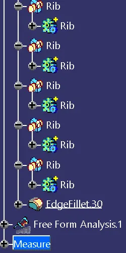
- Screenshots of the expanded Tree Structure for the Geometrical Sets and the Part Body.
- Screenshots of the 3D Part model in various orientations (Isometric, Front, Side, and Top View), Yellow color- B-pillar surface model