Door Arm Rest Week 8 Challenge
Title- Creation of Door Arm rest
Aim- To create the door arm rest component using the given class A surface of the arm rest and door .
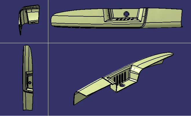
Objectives –
- To create class B and C surface from given class A surface
- To make solid closed body model using class C surface
- To perform draft analysis for class A surface and solid body w.r.t tooling axis and side core axis.
- To publish class A,B,C surfaces, Tooling axis and side core axis.
Introduction-
This report demonstrate the design of door arm rest an automotive plastic component with industry principle like determine and implementation of tooling axis, side core axis, draft analysis, draft angle, creation of class B and C surfaces and maintain thickness of part at 2.5 mm. The plastic component is designed with surface and part design technique in CATIA.
Methodology-
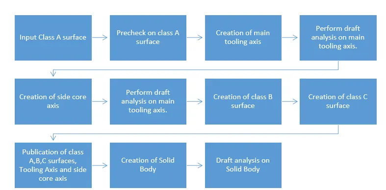
Fig. 1 Methodology for designing of door arm rest
Some term are defined before designing-
- Class A surface-
- A surface is made by designer and surface design is given to modeler to work on it.
- It is aesthetic surface and the outer most surface of any automotive component.
- Class A surface is referes to those surfaces which are visible and abide to the physical meaning in a product. this classification is primarily used in any automotive and increasingly in consumer goods industry.
- thats why exterior of automibles is deemed is class A surface.
- Class B Surface-
- A surface which is below a certain thickness from class A surface is called as class B surface. It contains engineering aspects of a model.
- it is genrally visible from back side of class a surface.
- Class B surafce is designed as per class A surface.i.e the continuity , thickness of component, functionality etc. should be maintained.
- Class C Surface-
- A class C surface that join class- A and Class B surface along tooling axis
- It contains draft as per design..
- It is basically thickned surface between class A & B surface.
- Tooling axis- It is a direction in which mould/ core and cavity opens.
- Analyze model visually to see which direction is most suitable for tooling axis and draft analysis is doen along tooling axis.
- Side Core axis- some walls are difficult to clear through tooling axis itself. These features may have negative draft angle which cannot be ignored, so they need a different tooling direction for clearing the part in the mold. Such type of tooling direction called as side core axis.
- Draft- it is an angular tapering given in the direction of mold movement at design stage to every plastic components that has to be manufactured. The draft allows the part to release easily from the mold without creating friction between the surface of component and core- cavity plates. In most application require minimum draft angle of around 0.5 to 1°, however 3° draft angle is widely accepted for cost saving purpose.
- Draft Analysis- it is a tool in CATIA which analyze and identifies zones which are deviates from specified angle value along specified draft direction using color codes.
step-1 :- Input surfaces
- Below fig. 2 shows input received from designer. Pink color part is side door and blue color part is plastic arm rest.
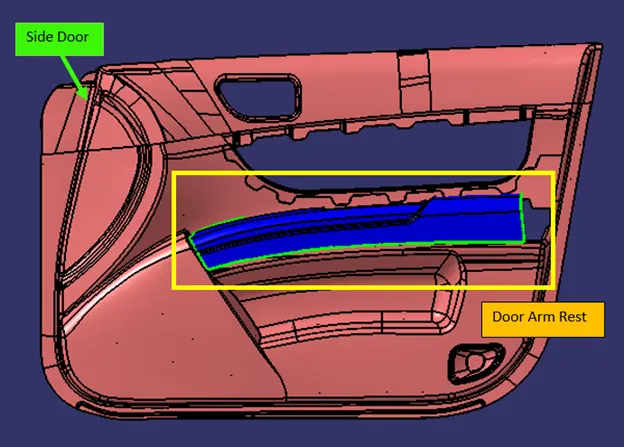
Fig. 2. Given Input door arm rest and door
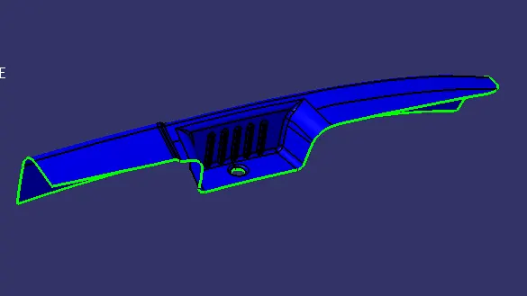
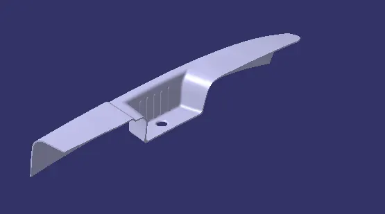
Fig. 3 Door arm rest component in Isometric view
Step- 2 Design check (Pre-check) of input given door arm rest
- After receiving class A surface/ door arm rest shown in fig.3 , check the connectivity of surfaces.
- First important thing is to check continuity of given class A surface i.e to ensure that class A surface is properly joined or there is no discontinuity in the model. This can be checked by using two options, Join or Boundary feature in CATIA. 3 shows connectivity of class A surfaces.
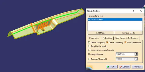
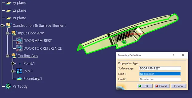
Fig. 4 Joined and Boundaries of surfaces shows connectivity
Step-3 Determine the tooling axis
- Identify the surfaces which can creates problem while manufacturing with all 3 axes.
- After analyzing tooling direction of class A surface, it found that there is need of two tooling direction/ axis.
- Here we have created dummy tooling axis before creation of main tooling axis.
Following procedure is used to create dummy tooling axis-
- A Hole boundary of class A surface is extracted and fill it shown in Fig. 5
- Create a point on the surface at center using point command, shown in Fig. 6
- Generated a line along Z-direction using point- direction command shown in Fig. 7. And this line is dummy tooling axis for reference.
- For draft analysis along z- axis will not cleared all surface, hence need of main tooling axis.
- New axis system is inserted at point, shown in fig.8
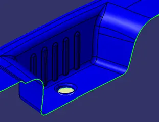
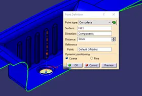
Fig.5 Bounadry is filled Fig. 6 Point is created on surface
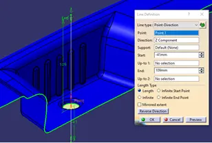
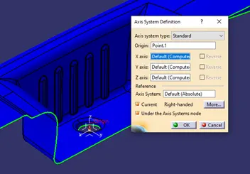
Fig.7 Line is created on point Fig.8 Axis system is inserted
- Tooling Axis in Y direction-
- Create a position sketch on ZX plane and use intersect 3D.
- Draw line on inclined surfaces and take bisection of both line, this is tooling axis in y direction.
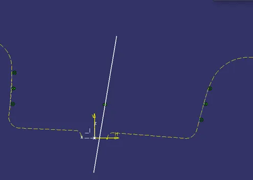
Fig.9 Tooling axis in Y direction
2. Tooling Axis in X direction-
- Create a position sketch on YZ plane and use intersect 3D.
- Draw line on inclined surfaces and form center at an angle of 4°.
- Take bisection of both line, this is tooling axis in X direction.
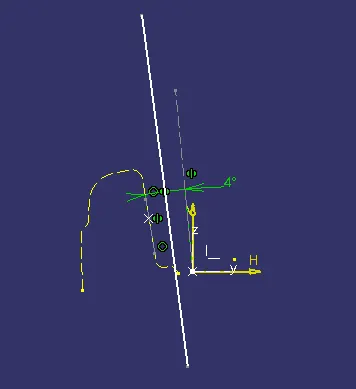
Fig.10 Tooling axis in X direction
3. Main Tooling Axis-
- Bisect both the tooling axis in X and Y direction to get main tooling axis, shown in Fig.11
- fig.12 shows arm rest surfaces are not cleared along created tooling axis.so there is need to create new tooling axis.
- Perform the draft analysis through the created line on the arm rest component.
- If all wall clearance is not achieved, orient the compass as per requirement.
- When all rest arm surfaces are turned into green color/ clearance is achieved, lock the compass orientation.
- Now edit the line definition, use point direction method in which use created point and direction to the compass direction.
- This is our main tooling axis (Purple in color) for arm rest component shown in fig.13.
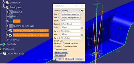
Fig. 11 Line created using tooling axis in X and Y direction
Step- 4 Draft Analysis along tooling axis
To perform draft analysis on class A surface go to- Insert > Analysis > Feature Draft Analysis.
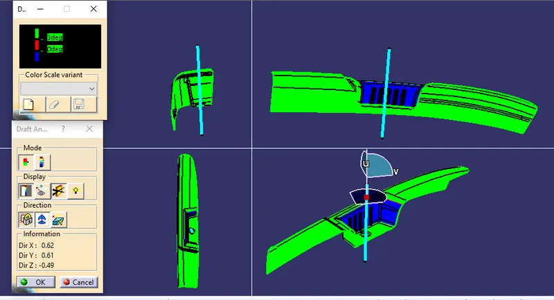
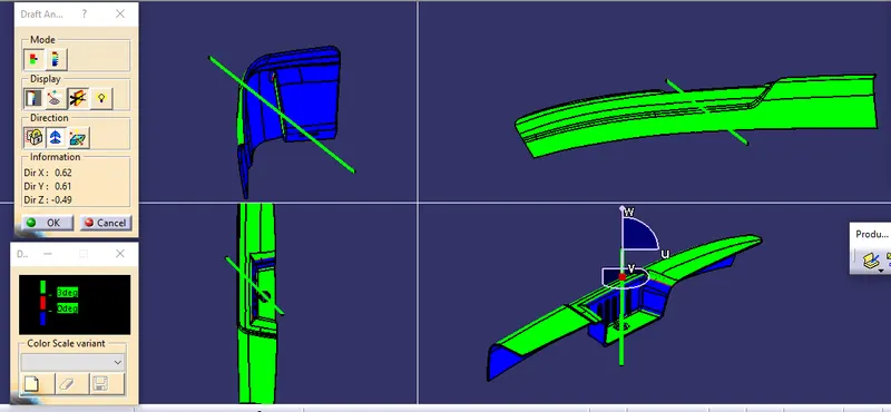
Then perform draft analysis on each tooling axis. Make sure that before switching to draft analysis part should be in customer view parameter with material option of mesh. Next step is to align the tooling axis with class A surface by clicking on compass icon and drag it to tooling axis. After clicking on surface we get tab and it shows different color scales with different draft angle range. The minimum draft angle is 3°. From fig. 12we can see that red color shows 0° of draft angle, green color is above 0° and blue color is below 0°. So try to keep draft angle positive.
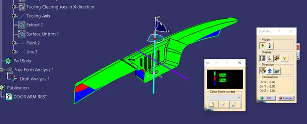
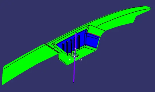
Fig.12 Draft analysis along Main tooling axis. Fig. 13 Draft analysis with new main tooling axis
Step-5 Side core axis
- To clear the bin wall a side tooling along y direction can be considered as a possibility.
- To create point on center of surface, pocket surface is extracted and untrimmed it fig. 14, 15,16 .
- Create a line along Y axis through a point which is created on surface shown in Fig. 17.
- Perform the draft analysis through the line.
- If clearance is not achieved, orient the compass as per requirement.
- When all bin surfaces are turned into green color/ clearance is achieved, lock the compass orientation.
- Now edit the line direction to the compass direction.
- This is our final side core axis for bin wall.
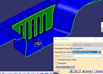
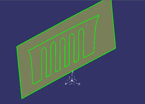
Fig. 14 Pocket surface in extracted Fig.15 untrimmed the extracted surface
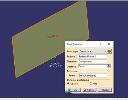
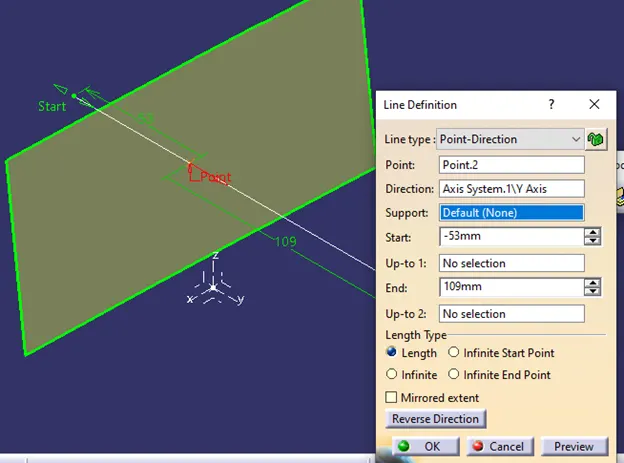
Fig. 16 Point is created on center of surface Fig.17 Line along Y direction
Step- 6 Draft Analysis for side core
Follow the same procedure used for draft analysis along tooling axis.
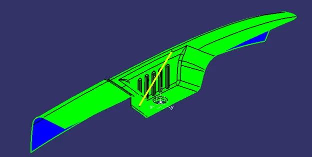
Fig. 18 Draft analysis of side core along created line Fig. 19 Draft analysis along compass direction
Step-7 Creation of class B Surface
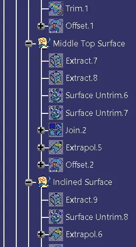
For creation of class surface here we made a geometrical sets w.r.t each surface orientation for easy understanding and working-
- Side surface-
- Extract the side surfaces from class A surface.
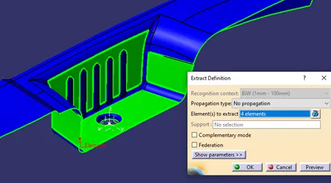
- Untrim the extracted surfaces and then extrapolate the untrimmed surface such that they intersect each other.
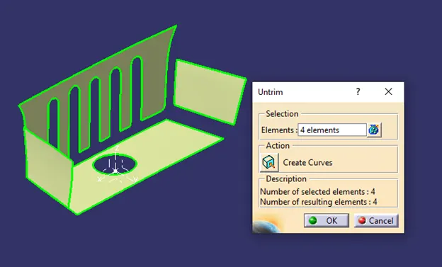
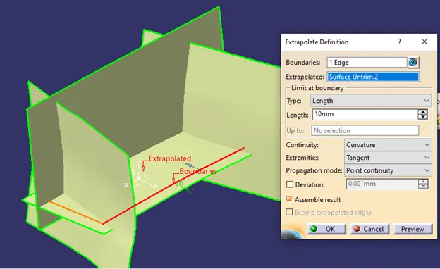
- Trim the surfaces and an offset them at 2.5 mm
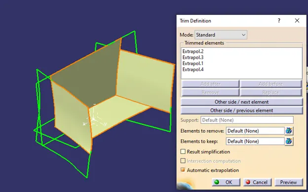
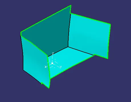
2. Middle Top surface-
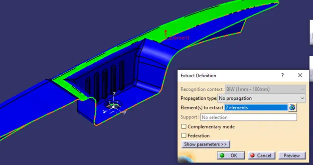
- Extract the two middle top surfaces form class A surface
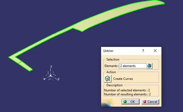
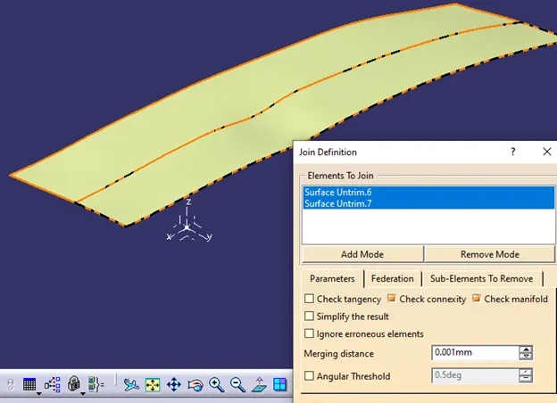
- Untrim the extracted surfaces and join the both untrimmed surfaces together.
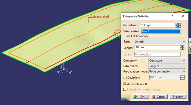
- Extrapolate the joined surface and offset the joined surface at 2.5 mm.
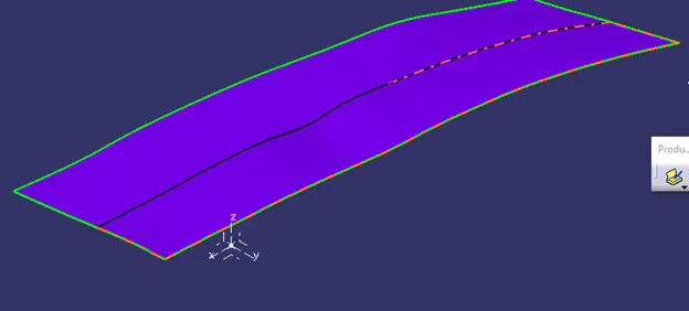
3.Inclined surface-
- Extract the inclined surface form class A surface
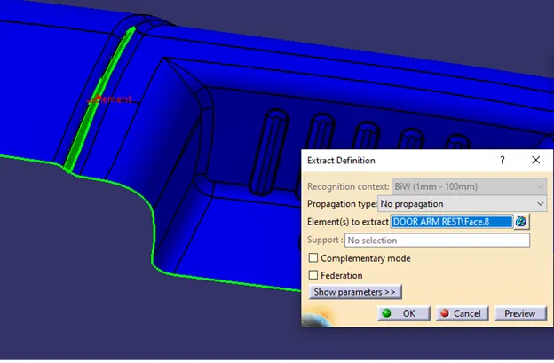
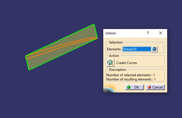
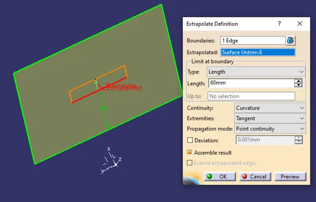
- Untrim the extracted surface, extrapolate the untrimmed surface and offset at 2.5mm.
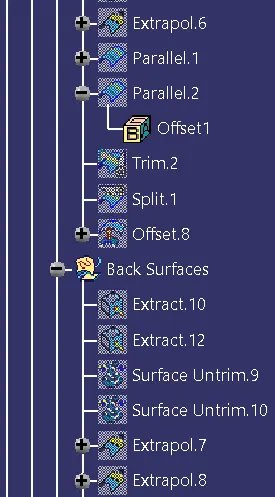
4.Back Surfaces
- There are two back surfaces/ walls for class A surface, extract both surfaces
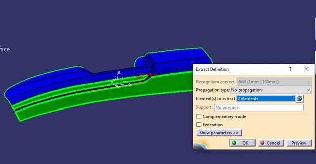
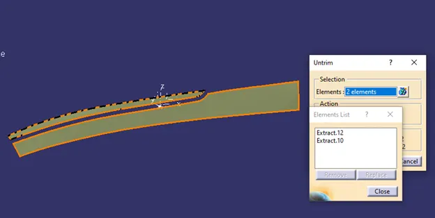
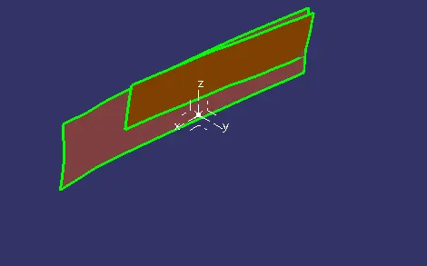
- Untrim both surfaces, extrapolate and offset the extrapolated surface at 2.5 mm
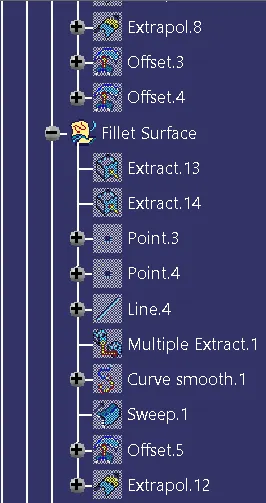
5.Fillet surface
- The fillets at the backsides of the class A surface cannot be created directly because of the back surfaces/ walls are trimmed together. There is only one surface with two fillets.
- Extract the edge of fillet from class A surface.
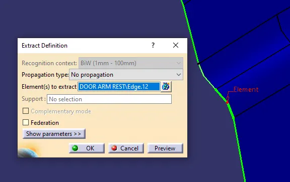
- Create a mid-point on both extracted curve.
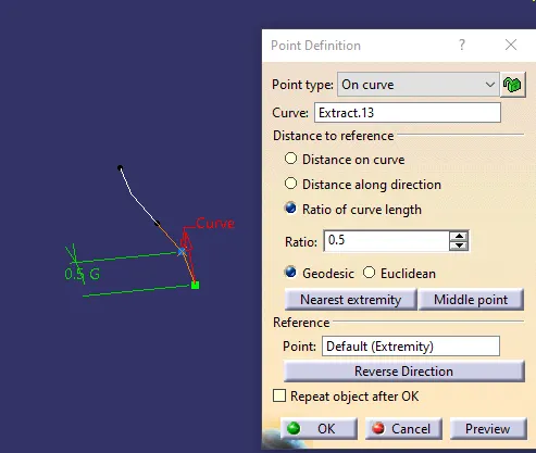
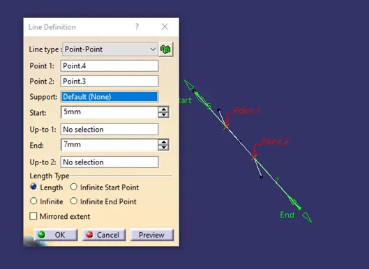
- Create line which is passing from both created mid points and this is used as profile to create a surface with sweep feature.
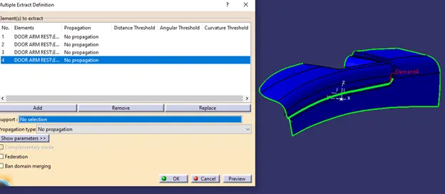
- Use multi- extract feature to extract the fillet edge, which will used for guide curve.
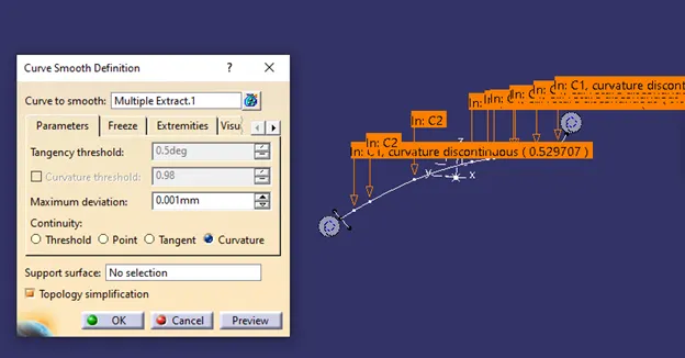
- Convert multi extracted curve into smooth curve.
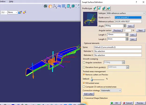
- Used sweep feature to create surface with reference surface subtype. Here constructed line is used as a profile and smooth curve is as a guide curve.
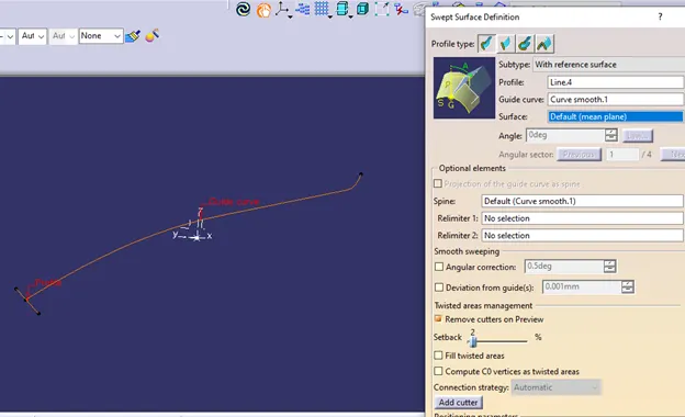
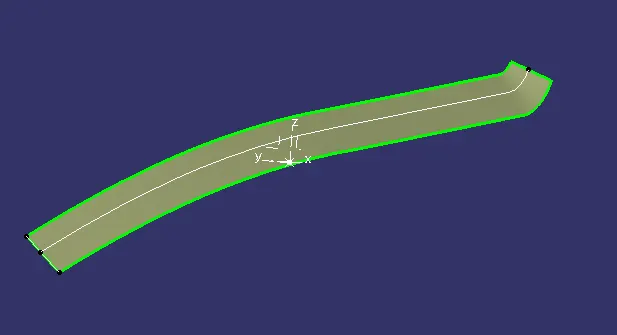
- Extrapolate the created surface and offset it at 2.5mm
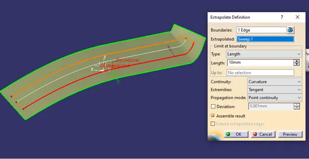
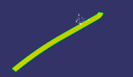
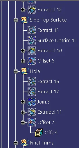
6. Side top surface
- Extract the side top surface from class A surface and untrim the extracted surface.
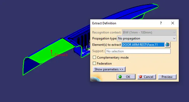
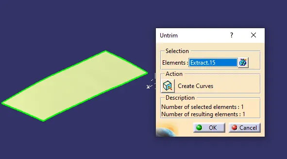
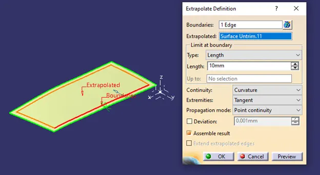
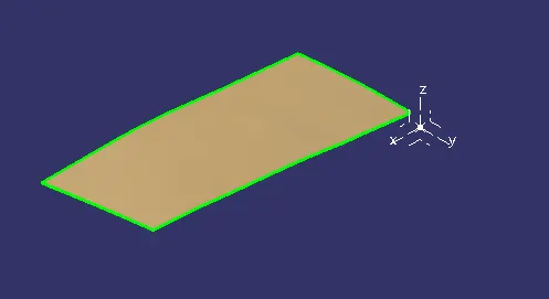
- Extrapolate the untrimmed surface and offset it at 2.5 mm
7. Hole
- At a bottom of class A surface, there is a hole with inclined cylindrical wall. Extract the cylindrical surface.
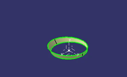
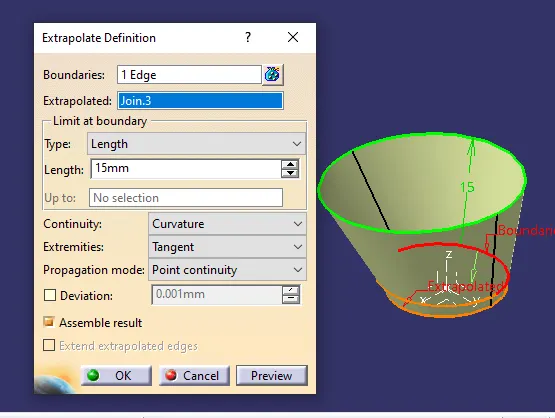
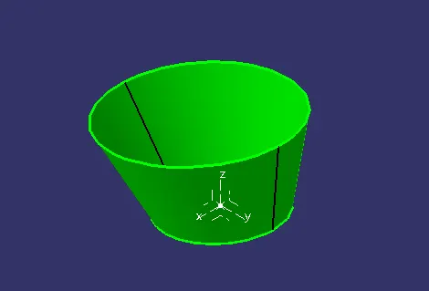
- Extrapolate the extracted surface and offset it at 2.5 mm.
8. Final trims-
- Before doing final trimming of all surfaces together, the inclined surface need to be modified.
- On the inclined surface, create curve using the parallel curve feature such that the curves do not touch the side surfaces.
- After that use trim feature to cut the parallel curves and then split inclined surface using curves.
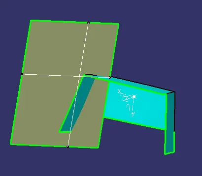
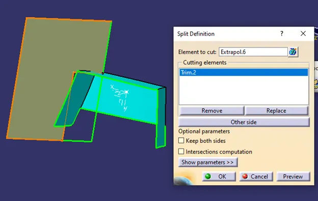
- Offset the splitted surface at 2.5mm
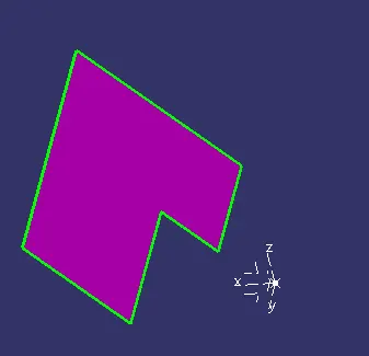
- Trim the middle top surface and last trimmed side surface together.
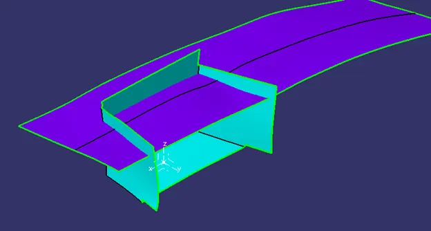
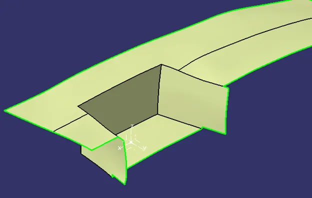
- Trim the upper back surface and last trimmed surface together.
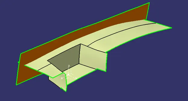
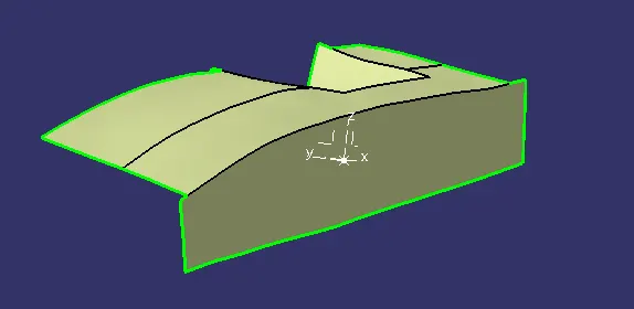
- Trim the fillet surface and last trimmed surface together.
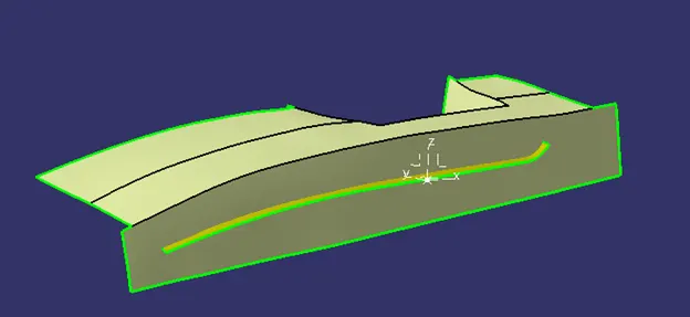
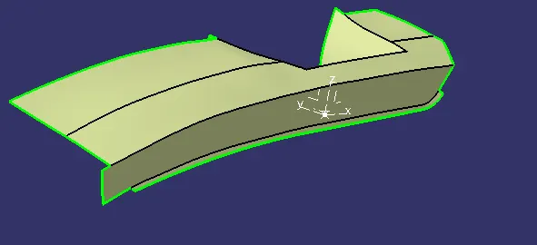
- Trim the modified inclined surface and last trimmed surface together.
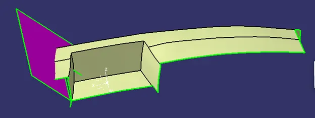
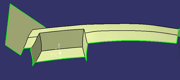
- Trim the side top surface and last trimmed surface to gether.
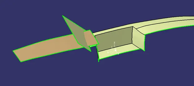
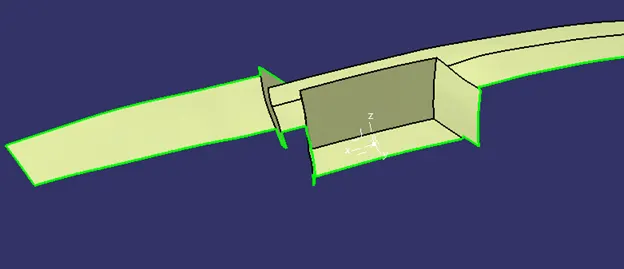
- Trim the lower back surface and last trimmed surface together
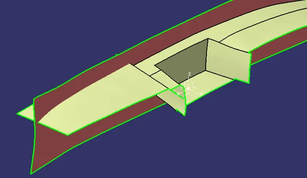
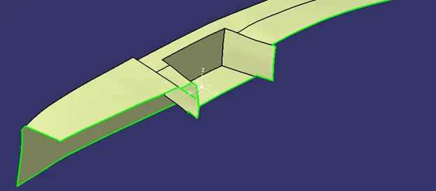
- Finally trim the hole from last trimmed surface together.
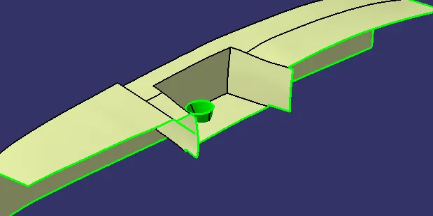
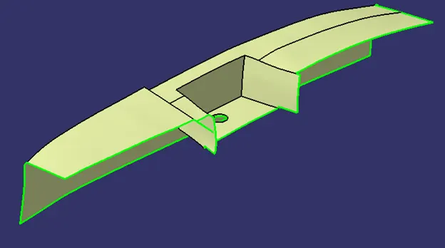
9.Edge Fillets-
- Provides the proper fillet on edges by taking reference from class A surface.
- While applying fillet radius, it should be keep in mind that thickness of component such that when the final part is created, it has a uniform thickness of 2.5mm.
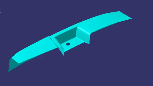
Step- 8 Creation of Class C surface.
- Extract the boundary of class A surface using multiple extract feature and make the curve smooth.
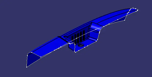
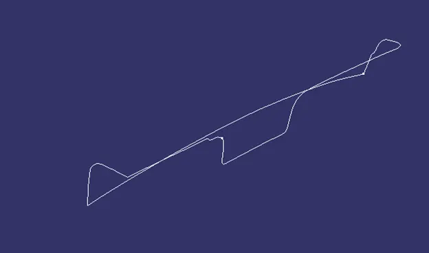
- Use the sweep feature of with reference surface to make surface using guide curve as a smooth curve and reference surface as class A surface.
- Join the swept surface and class A surface to gether.
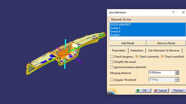
- Trim the class B surface and swept surface together.
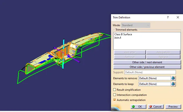
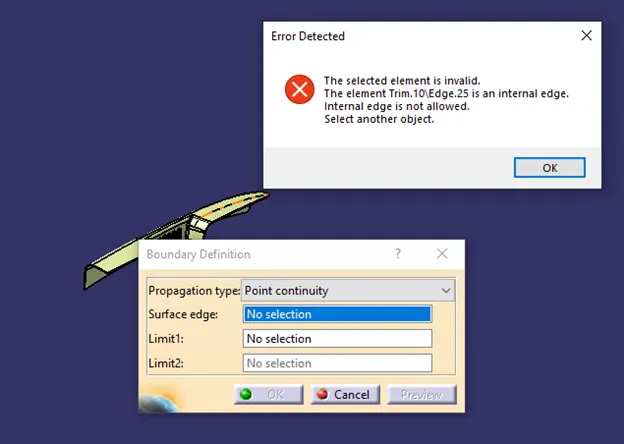
- Class C surface doesnot contain any open surface or boundary.
Step- 9 Publication
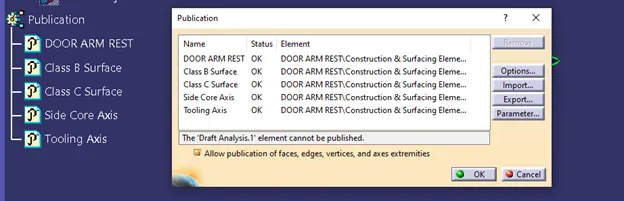
- This feature is used to make easy access of published component (Surface or Sketch).
- Here class A,B,C surface, tooling axis and side core axis is published.
- Path- Tools > Publication > Select entity (Surface/ Sketch/Body)
step-10 Creation of solid body
- Solid body is created using class C surafce.
Step 11- Draft Analysis on Class A surface and arm rest Solid body
- Screenshots of the class A surface model along tooling axis with the proper color code of the draft angle in various orientations (Isometric, Front, Side, and Top View)
- Screenshots of the solid body model along tooling axis with the proper color code of the draft angle in various orientations (Isometric, Front, Side, and Top View)
- Screenshots of the class A surface model along Side core axis with the proper color code of the draft angle in various orientations (Isometric, Front, Side, and Top View)
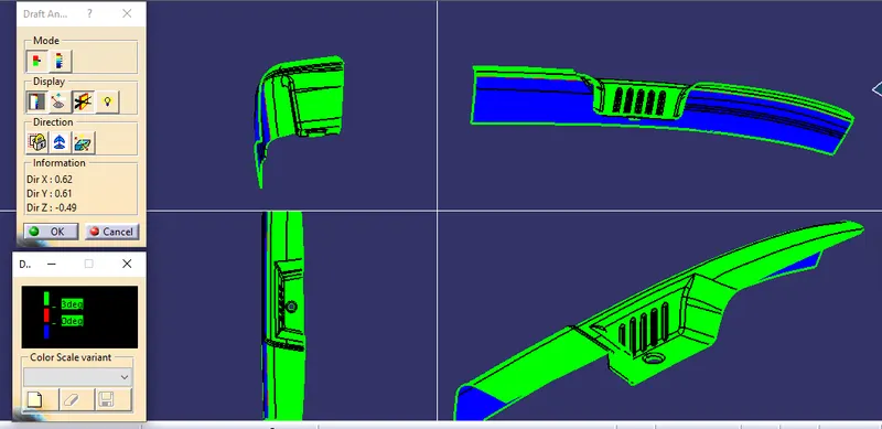
- Screenshots of the solid body model along Side core axis with the proper color code of the draft angle in various orientations (Isometric, Front, Side, and Top View)
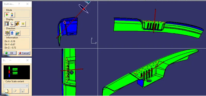
- Screen shots of tree structute, geometrical str. of tooling axis, side core axis, class B,C surfaces and draft analysis.
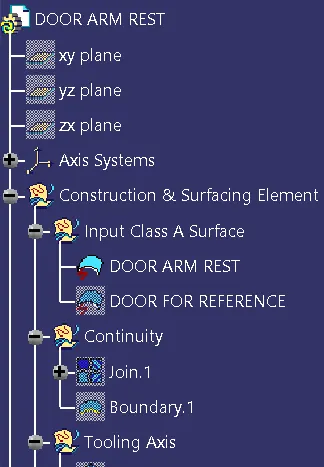
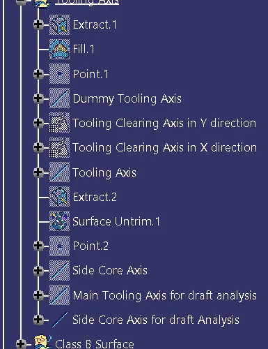
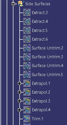
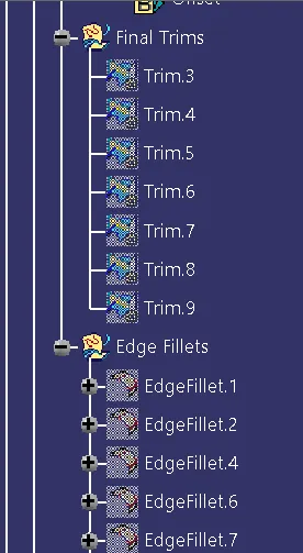
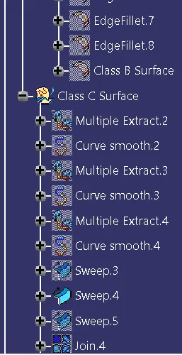
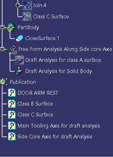
- Screenshots of the solid model in various orientations (Isometric, Front, Side, and Top View)
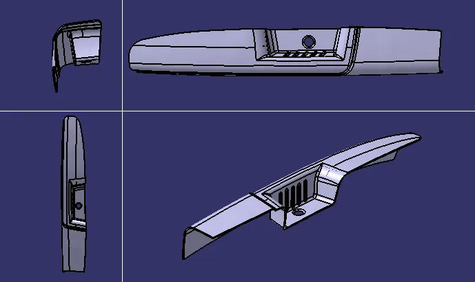
- Screenshots of the Class C Surface in various orientations (Isometric, Front, Side, and Top View)
- Conclusion-
- The tooling axis and side core axis are identified and created for class A surface.
- The class B and C surface are created from given class A surface in CATIA V5.
- The solid closed body model is made using class C surface.
- Draft analysis is performed for class A surface and solid body w.r.t tooling axis and side core axis.
- To publish class A,B,C surfaces, Tooling axis and side core axis.
Note- I have make two catia part files because i was not able to perform draft analysis on same part/ surface wr.t tooling axis and side core axis.