Week 9 - Attachment Feature Creation - Challenge 2
Attachment Feature Creation - Challenge 2
Title- Create the boss and Dog House for the Centre console coin holder considering the design rules.
Objective- The aim of this challenge is to create the boss and Dog House for the Centre console coin holder plastic component considering the design rules with industry principle and perform draft analysis.
Thickness of the component is 2.5 mm.
Theory-
Class B surface contains all the engineer data required for the model to be completed. This data involves designing of various features. Some of the major feature of the class B surfaces are- Ribs, Screw Boss, Dog House.
We have already created coin holder plastic component using class A, B and C surfaces.in last challenge we have worked on rib attachment feature which is important because they allowed us to make a component rigid without making part too thick. Now in this challenge we are going to work on screw boss and dog house attachment feature.
Screw Boss-
Boss feature finds use in many part designs as a point of attachment and assembly. The most common variety consists of cylindrical projections with holes designed to receive screws, threaded inserts, or other types of fastening hardware. Under service conditions, bosses are often subjected to loadings not encountered in other sections of a component. Provide a generous radius at the base of the boss for strength and ample draft for easy part removal from the mold.
Here we are going to make boss for center console coin holder plastic component with some general design rules like ribs. An ideal boss is designed according design rules of ribs, then it would not produce sink marks on component or stick in the mould. But unfortunately the tubular form of the boss would not be strong enough in many cases. In Most cases bosses are breaks rib design rule and due to this boss design compromise between sink marks and functionality. Rigidity is a simple aspect of boss design, this is achieved by linking bosses to the side wall and ribs.
General Guidelines for Bosses:
- Draft - 0.5 degrees on walls of boss
- Thickness - Typically 40%* of the nominal wall at the base.
- Height to Diameter Ratio - 3:1
- Radii - 0.25mm maximum radii.
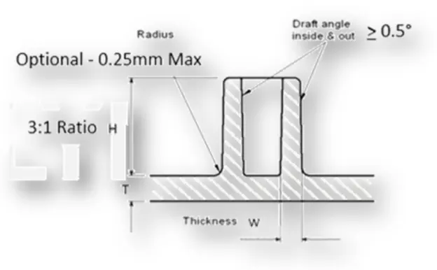
Procedure for design of boss on component-
- Extract the base surface of coin holder part from Class B side.
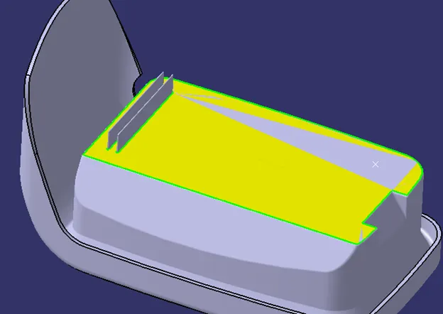
- Create circles on extracted surface, make sure that we are using position sketch on surface or XY plane and sketch should be iso-constrained.
- Here I’m taking M6 standard for designing of screw boss-
Thickness (w)= 0.6*t (wall thickness of component)
= 0.6*2.5 = 1.5 mm for single side
w= 3 mm for both side
Overall thickness (W)= 6 +3= 9 mm
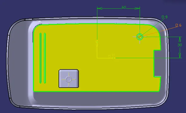
- Extrude the created sketch, for the extrude distance use design rule which is mention above i.e H/D= 3:1.
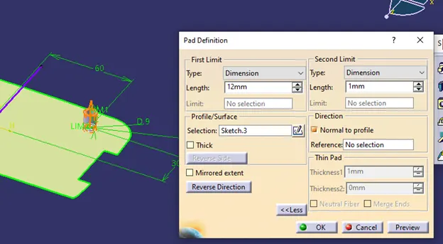
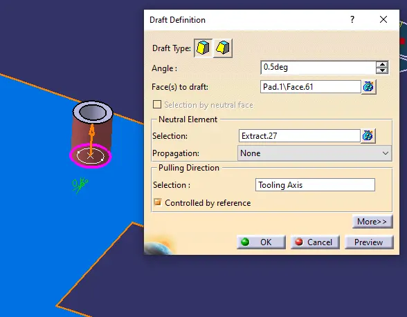
- Apply draft of 0.5 ° on outer surface of boss along tooling axis with neutral element is extracted surface.
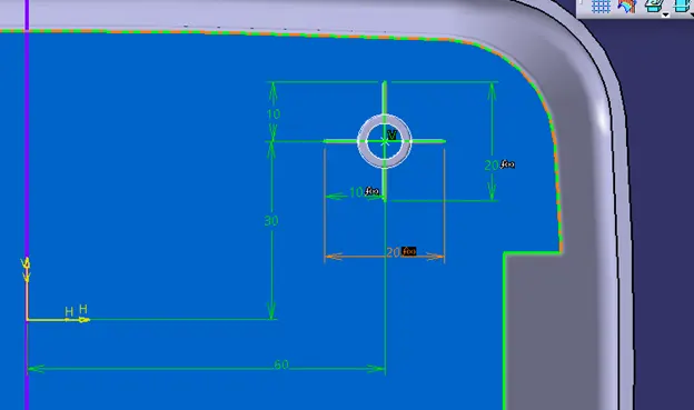
- Again rib create a sketch on exacted surface.
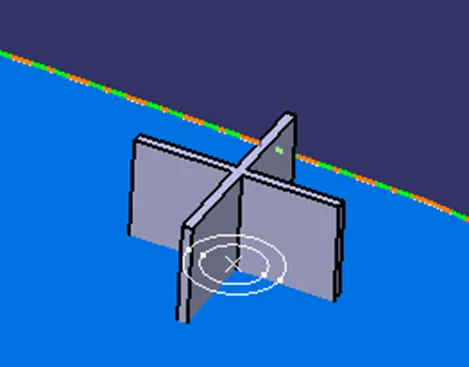
- Thicken the created sketch using pad command at 1mm and apply draft of 0.5 °to vertical surfaces along tooling axis.
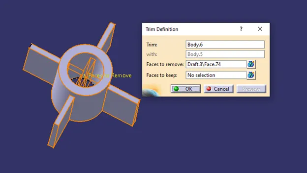
- Add the ribs into the created boss body using union trim and remove inner side ribs portion. Finally add both the boss and union trim ribs body assemble to main part body.
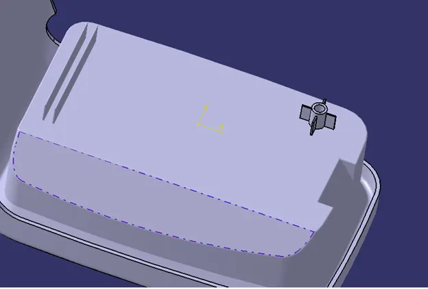
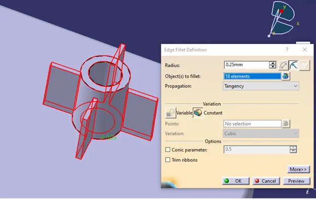
- Apply edge fillets of R-0.25mm to rib edges.
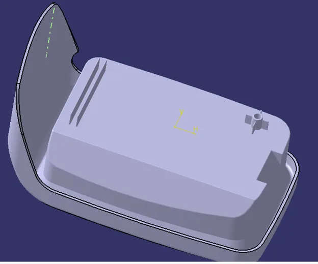
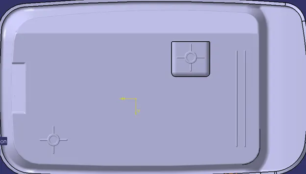
Now here if we want boss more than one then, we can make copy of created boss and then transfer as per out design requirement.
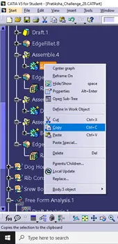
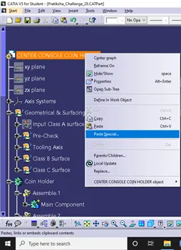
Process- Copy boss body from body tree structure and paste special in to our main design ( use paste with all link)
Transfer the solid body wr.t coordinates i.e X,Y,Z.
Dog House-
Dog house is an engineering feature used in plastic trim design. Dog houses are used as supporting feature. Dog houses are subjected to draft analysis to prevent breakage of the component during ejection from mould cavity. Dog house and other engineering components are built on B-surface.
Procedure for creation of dog house-
- Create a plane which is parallel to XY plane at point on exacted surface.
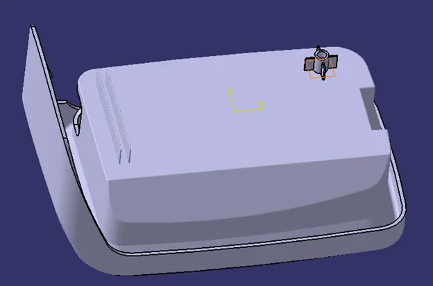
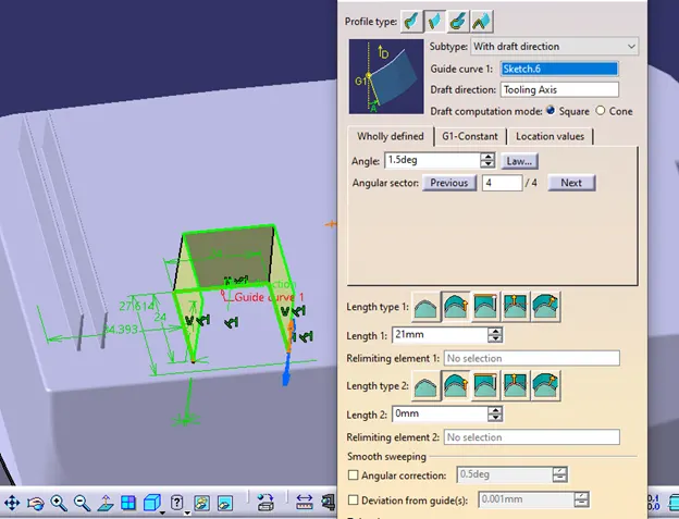
- Create a sketch on plane and sweep the sketch along tooling axis with angle 1.5° into surface modelling.
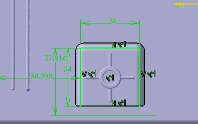
- Extract the base surface of class A surface and offset at 2.5mm and again offset the last offset surface at 20mm.
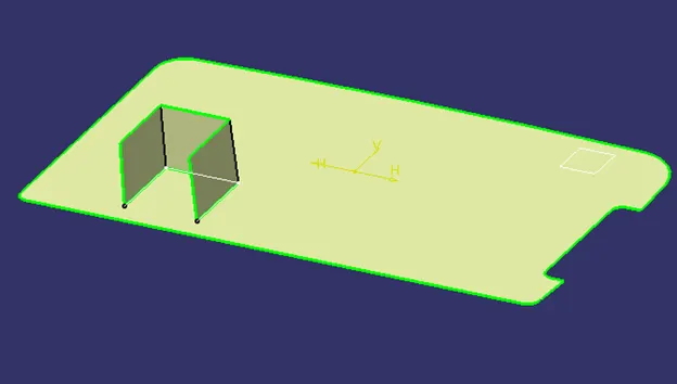
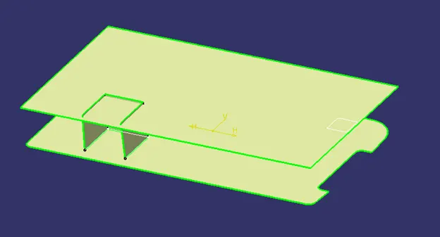
- Trim the swept surface and 20mm offset surface together.
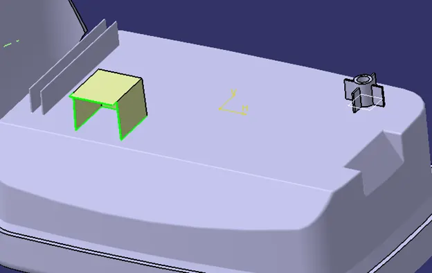
- Add new body and thicken the surface at 2mm from outer side into part modelling.Make front face equal in length.
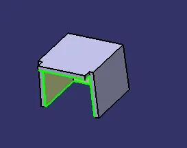
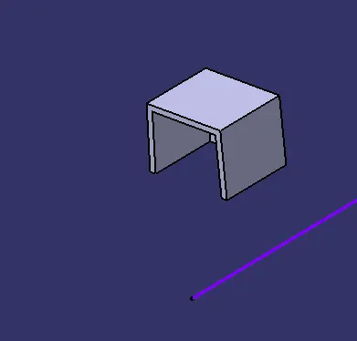
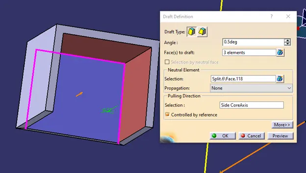
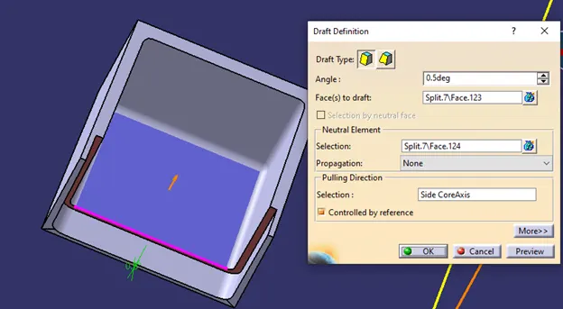
- Apply draft of 0.5 ° along side core axis.
- As we know that the function of dog house is to elevate the any other part like screw boss so that they can touch to datum surfaces. In some cases, the fixing part is not touched by the plastic part to tighten, so a dog house is used to resolve this problem.
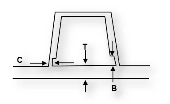
- The intersection part where the main part and dog house meets should have the 40% of thickness to main part. Height of intersection should be 3 to 6mm and thickness value at the intersections is 40% of 2.5mm which is 1mm but it vary after applying draft value. Thickness at one side is 1mm and at another side id 0.78mm
- For value B shown in fig.-Offset the base surface from side of class B surface at distance of 4mm.Extrapolate the offset surface.
- For value C shown in fig- Extract the inner surface of thicken bodt and offset at 1mm in outer direction. Extrapolate the offset surface.
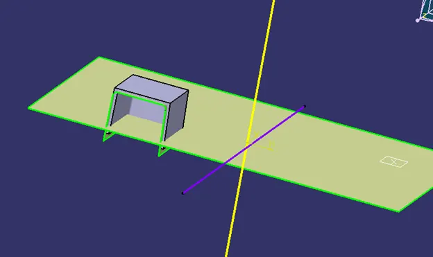
- Trim both extrapolated surfaces
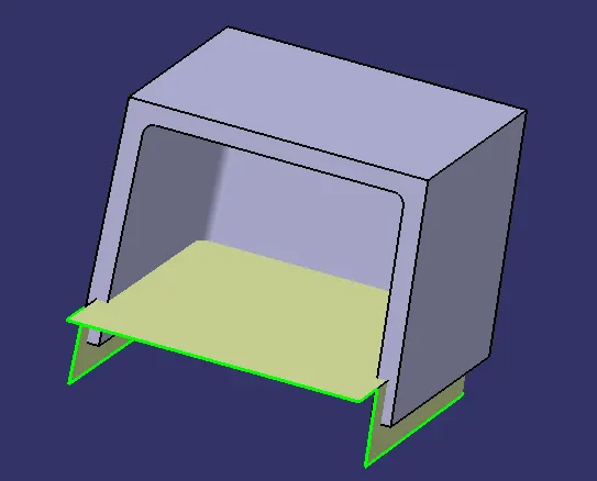
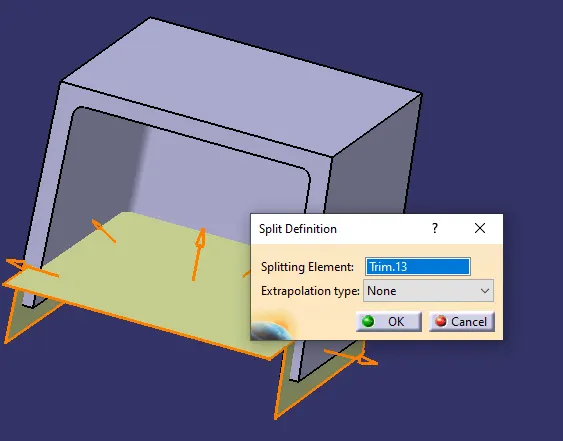
- Split the trimmed surface from thickened body.
- Apply draft of 0.5° along side core axis.
- Apply edge fillet of R.1 mm from inner side, R.3 mm from outer side and R0.5 mm at splitted sur face.
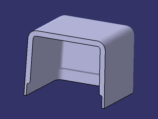
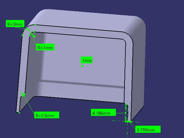
Move or transfer the screw boss on dog house by changing coordinate values.
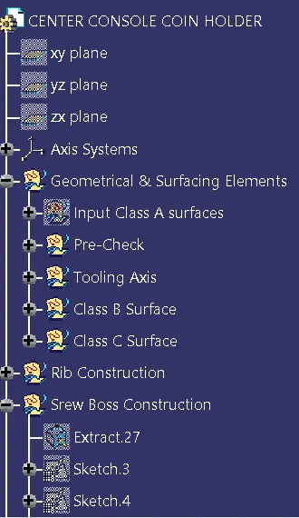
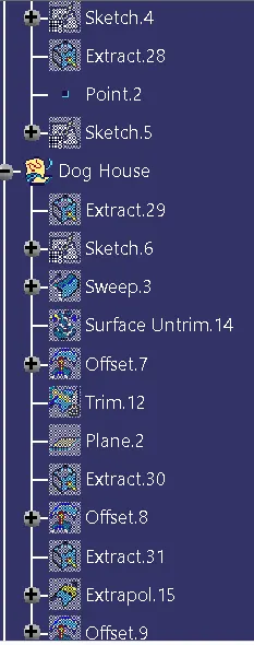
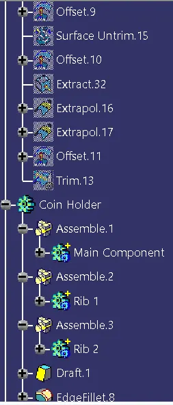
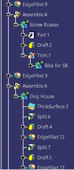
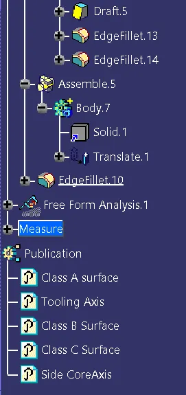
- Screenshots of the expanded Tree Structure for the Geometrical Sets , Surfaces and the Part Body.
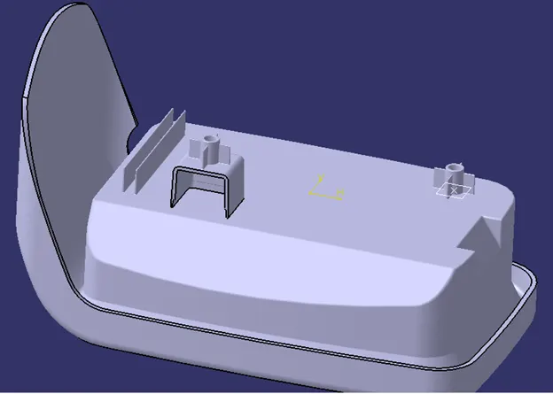
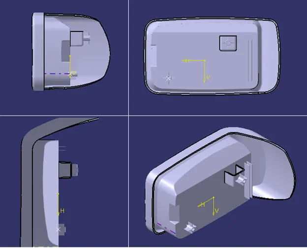
- Screenshots of the completed design in various orientations (Isometric, Front, Side, and Top View)
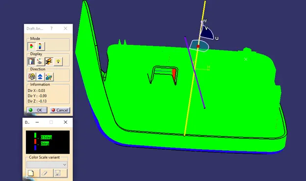
- Draft analysis along tooling axis
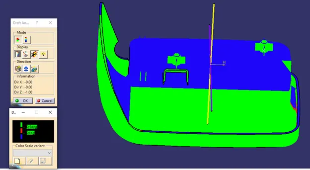
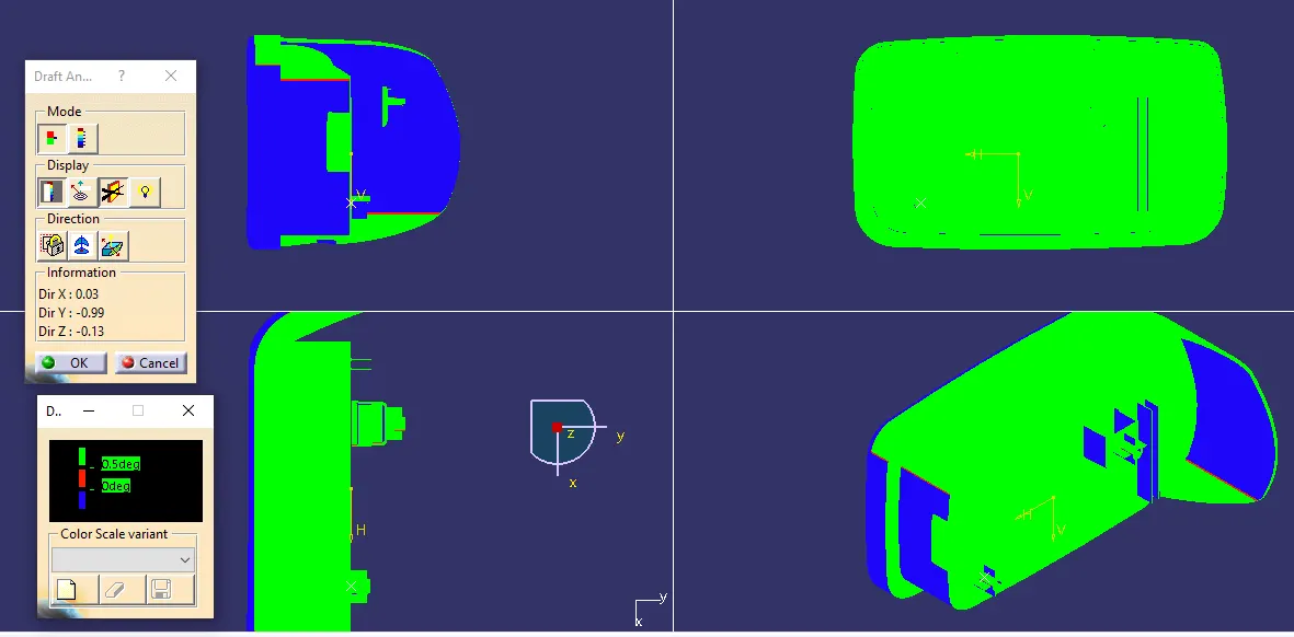
- Draft analysis along side core axis.
- Conclusion-
The screw boss and dog house is created for Centre console coin holder considering the design rules.