Week 8 - Challenge 3 - Switch Bezel Design
Switch bezel Design
- Objectives-
- To create the Switch Bezel Plastic component through the given Class-A surface. To begin with, the tooling axis for the given Class-A Surface is created meeting the requirements of the draft angle and at the end perform the Draft analysis on the model.
- Also to create class B and C surface of the Switch Bezel Plastic component.
Take the Thickness of the component to be 2.5 mm
- Introduction-
- Tooling axis is a direction in which mould/ core and cavity opens.
- By providing tooling axis to the component, we can do the draft analysis of the component. Draft analysis is performed on component where the ejection of materials happens after the materials is made inside the tool.
- Class A surface- The surface is made by designer and surface design is given to modeler to work on it. It is aesthetic surface and the outer most surface.
- Class B Surface- A surface which is below a certain thickness from class A surface is called as class B surface. It contains engineering aspects of a model.
- Class C Surface- A class C surface that join class- A and Class B surface.
- Methodology- Class A surface would be provided / given by styling team.
For the model of Base Bracket Plastic component, we will follow below methodology-
- Checking Continuity of given model surface i.e to ensure that class A surface is properly joined or there is no discontinuity in the model. This can be checked by using two options, Join or Boundary feature in CATIA.
- Tooling Axis- to find out the correct tooling axis of the component.
- Draft Analysis- to do draft analysis of class A surface.
- Class B –Surface- to create class B surface of the component.
- Class C- Surface- to create class C surfaces of the component.
- Publication- to publish tooling axis, class A, B and C surface.
- Solid Body- to creation from surface.
- Draft Analysis- to do draft analysis of solid body.
Extensively used tools for switch bezel surface creations are-
- Intersection
- Extract
- Un trim
- Join
- Trim
- Extrapolate
- Offset
- Boundary
- Line, Point
- Sweep
- Trim
- Edge Fillet
- Close Surface
- Checking Continuity of given model surface-
- To ensure that class A surface is properly joined or there is no discontinuity in the model. This can be checked by using two options, Join or Boundary feature in CATIA.
- Below images are showing that Class A surface model is imported in to CATIA V5 and it has continues connected boundary/ surfaces are joined and it is highlighted by green color line.
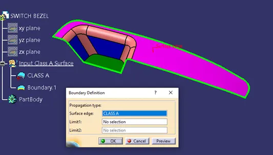
Fig. 1 Boundary of class A surface
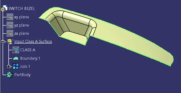
Fig. 2 Joined class A surface
- Tooling Axis-
- For creation of tooling axis, here we have to analyze the model carefully and focus on the surfaces which will create problem.
- From below fig. we can see that blue color surfaces might create problem while tooling so we have to focus on them and create tooling axis with respective them. And in last we will bisect both X and Y direction tooling axis to get out final tooling axis in Z-direction.
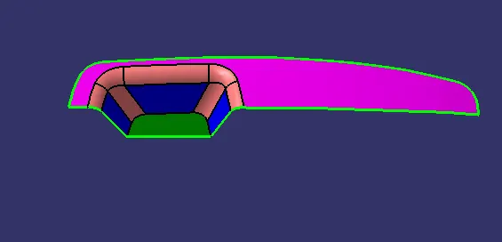
Fig. 3 Analyzed Surfaces
- Now we will make the tooling axis in both X and Y direction of the surfaces which we thought, they might create problems. Here point is created on bottom surface and new axis system is inserted on that point.
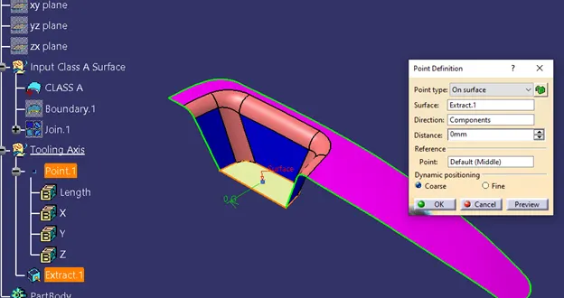
Fig.4 Point is created on bottom extracted surface
- For tooling axis in Y-direction, we used position sketch on plane YZ and intersect class A surface shown in fig. 5. Now for creation of axis two lines drawn and bisect them to get tooling axis in Y-direction shown in fig.7
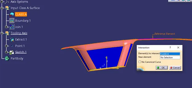
Fig. 5 intesection of class A suface in YZ plane
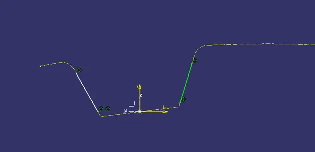
Fig. 6 Lines are drawn on intersected class A surface
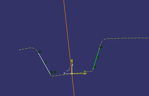
Fig.7 Bisected line
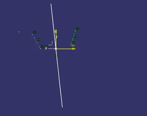
Fig. 8 Tooling Axis Y-direction
Similarly for tooling axis in X-direction, we have used position sketch on plane ZX and class A surface is intersected. Here only one surface is available, so line is drawn which is at angle 5.5 degree.
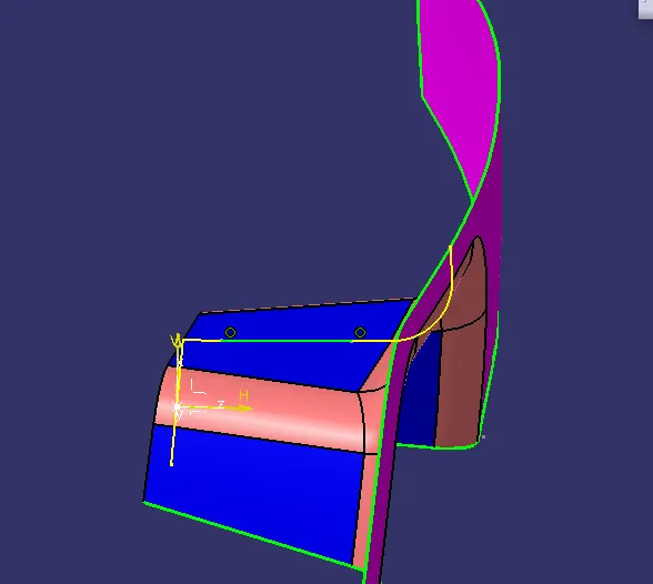
Fig. 9 intesection of class A suface in ZX plane
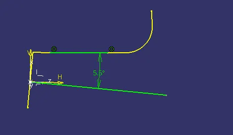
Fig. 10 line drawn at angle 5.5 degree
In last, we got our final tooling axis by using line bisector. We have used lines as a tooling axis in X and Y direction for line bisection purpose.
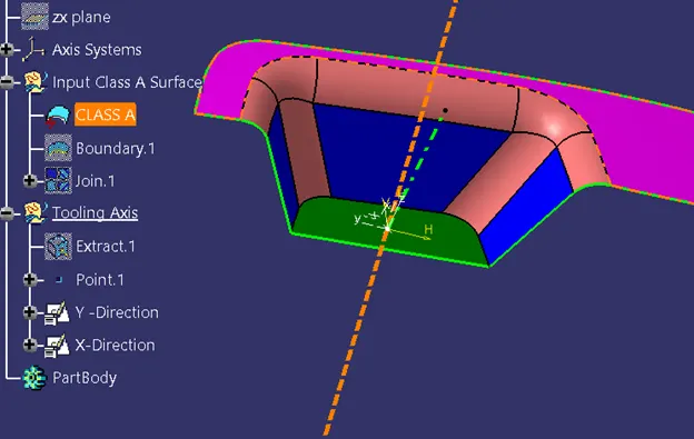
Fig. 11 Tooling axis in X & Y direction
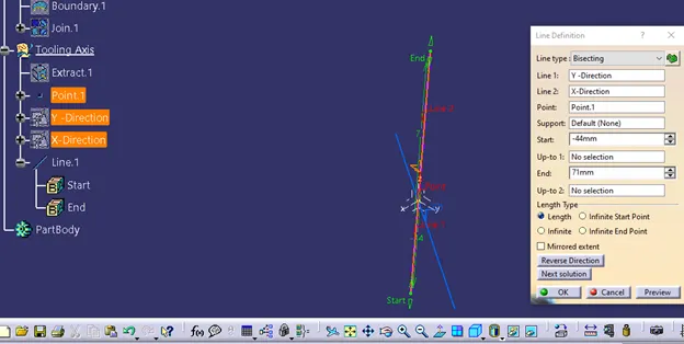
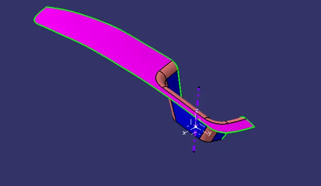
Fig. 12 Final tooling axis
3.Draft Analysis of class A surface
- The draft allows the part to release or eject from the mold. The draft angle is to reduce the friction between the core, part and cavity, and it’s also for avoid the damage of the core, part and cavity. The minimum draft angle is 0.5 degree but most commonly used draft angle is 3 degree.
- Path- Insert > Analysis > Feature Draft Analysis
- Make sure that before switching to draft analysis part should be in customer view parameter with material option of mesh.
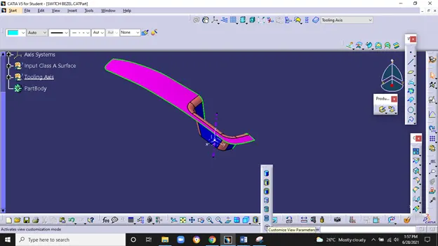
Fig. 13 Switch to Customer View Parameter
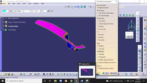
Fig. 14 Material Mode in Customer View Parameter
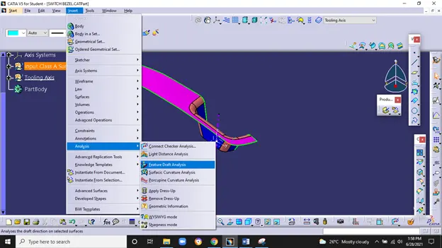
Fig. 15 Path for draft Analysis
Next step is to align the tooling axis with class A surface by clicking on compass icon and drag it to tooling axis.
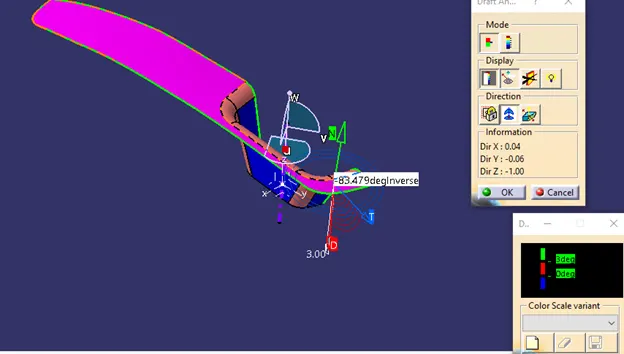
Fig.16 Alignment of compass
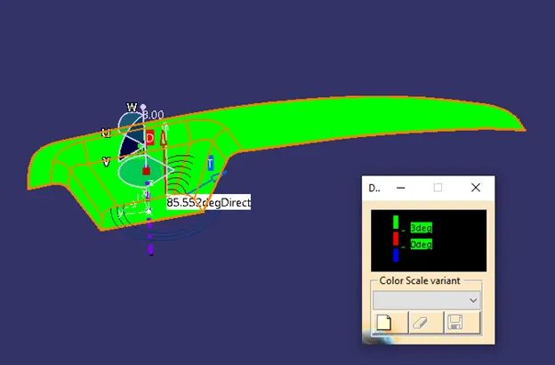
Fig. 17 Draft of 3 degree to the class A surface
- Click on the surface and see that the surface is within the permissible limit of draft angle.
- The surface should be green and in the column and analysis color box shows that draft angle is 3 degree.
- If any surface doesn’t show green color then we have to edit the tooling axis.
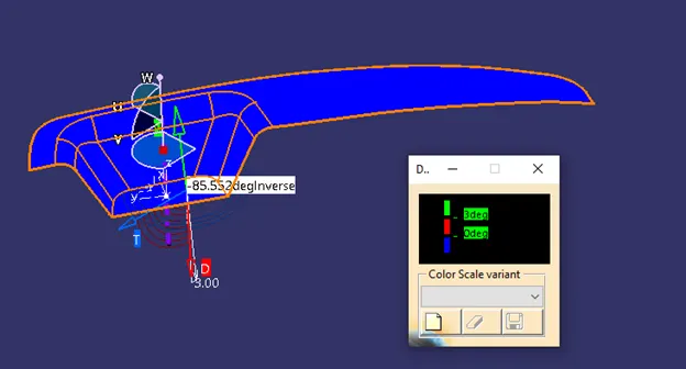
Fig. 18 Inverse draft direction
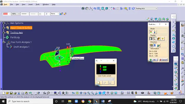
Fig.19 Draft angle at various location
4.Class B surface –
- In problem statement, thickness 2.5 mm is given for the component. Here we have created class B surface similar to class A surface at an offset of 2.5 mm.
- For easy understanding of feature tree structure, we have created class B surface using 3 geometrical sets.
- Rest Surface- Light green color
- Side walls- Blue Color
- Base – Dark Green color
A.Rest Surface-
- Top surface is extracted, then untrimmed it as shown in below fig.
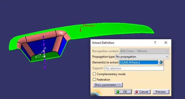
Fig. 20 top surface is extracted
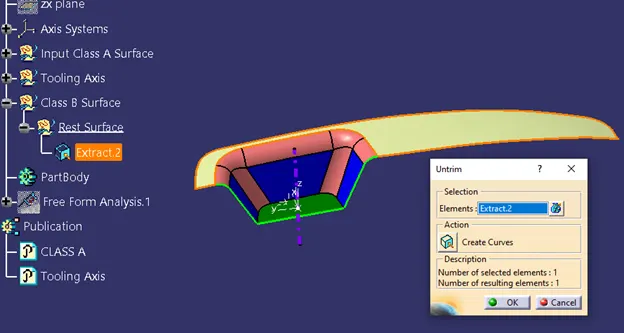
Fig.21 Untrimmed extracted surface
B. Side walls-
Blue color surfaces are extracted then untrimmed and extrapolated them with value one by one.
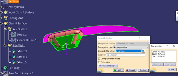
Fig.22 Extracted Surfaces
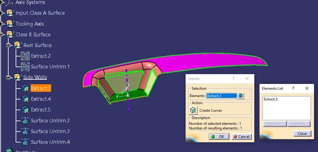
Fig. 23 Untrimmed extracted surfaces
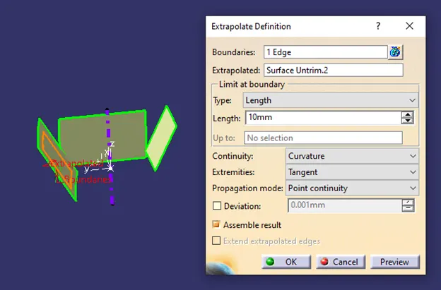
Fig.24 Extrapolated surfaces
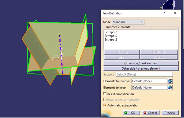
Fig. 25 Trimmed extrapolated surfaces
C. Base Surface
Similar procedure used here, first bottom surface is extracted and then untrimmed, extrapolated it value.
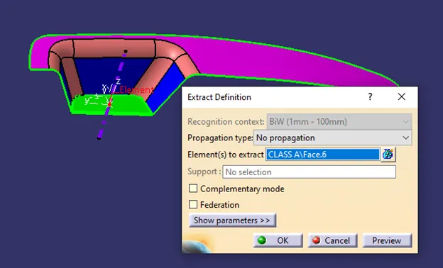
Fig.26 Base surface is extracted
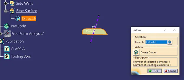
Fig. 27 untrimmed base surface
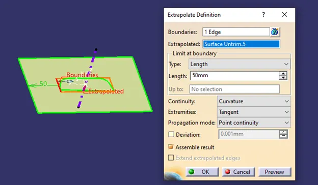
Fig.28 extrapolated base surface
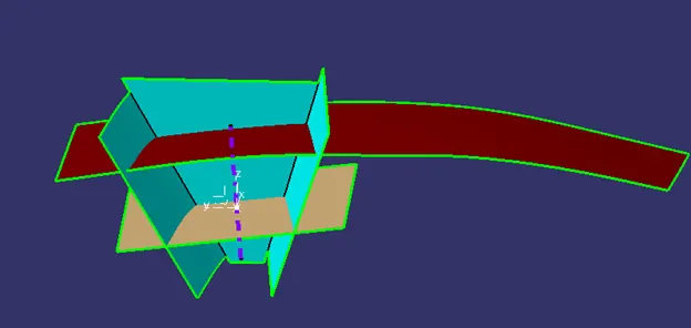
Fig.29 Rest, side walls and base surface
- All above surfaces are at an offset of 2.5 mm, which is the component thickness.
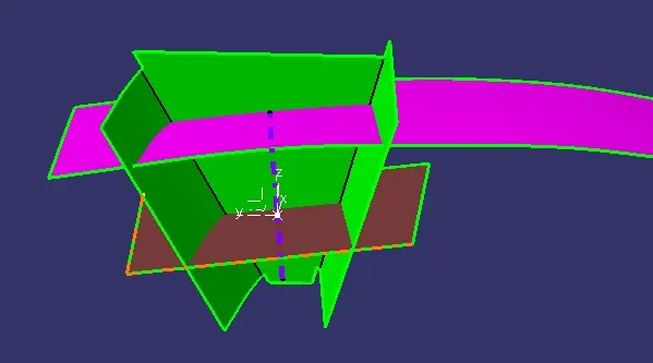
Fig.30 Rest, side walls and base surfaces at an offset of 2.5 mm
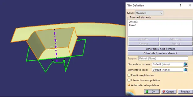
Fig. 31 Final trim for class B surface
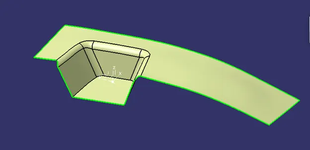
Fig. 32 Class B surface
5.Class C surface
To create class C surface, extract the boundaries of class A surface in to two geometrical set name as back side wall and front side wall.
Then use curve smooth feature to avoid a lot of patches and sweep the smooth curve along tooling axis.
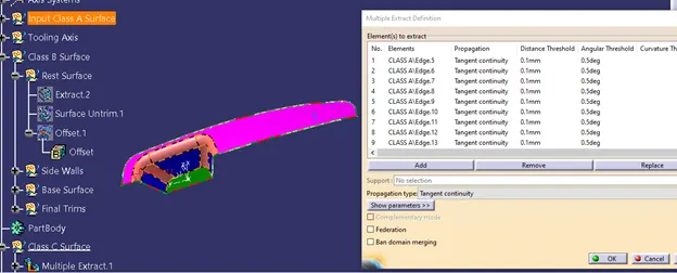
Fig. 33 Extracted boundaries of class A surface
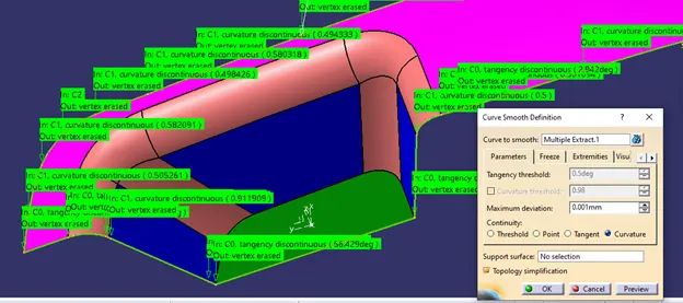
Fig. 34 Curve smoothen
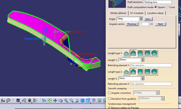
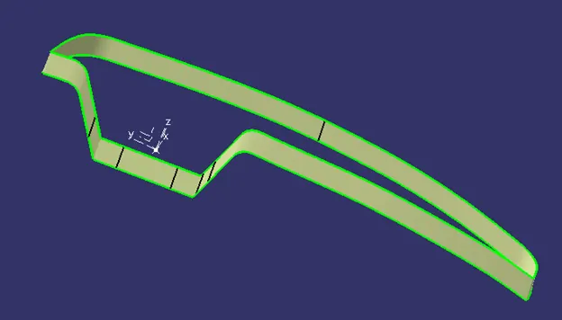
Fig. 35 Sweep for class C surface
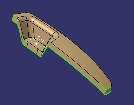
Fig. 36 Joined sweep and class A surface
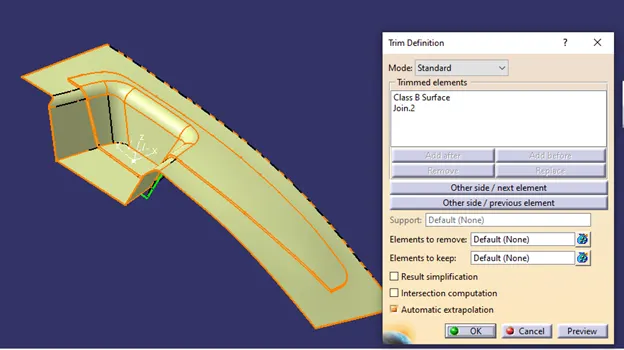
Fig. 37 Class B surface and joined are trimmed
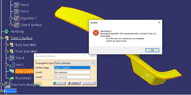
Fig. 38 Class C surface has no boundary
6. Publication
- Publication feature is used to make easy access of published component (Surface or Sketch), here class A surface and tooling axis is published.
- Path- Tools > Publication > Select entity (Surface/ Sketch/Body)
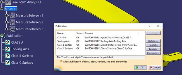
Fig.39 Tooling axis, surface A,B, and C are published
7. Solid body-
To create solid body, closed class C surface is used.
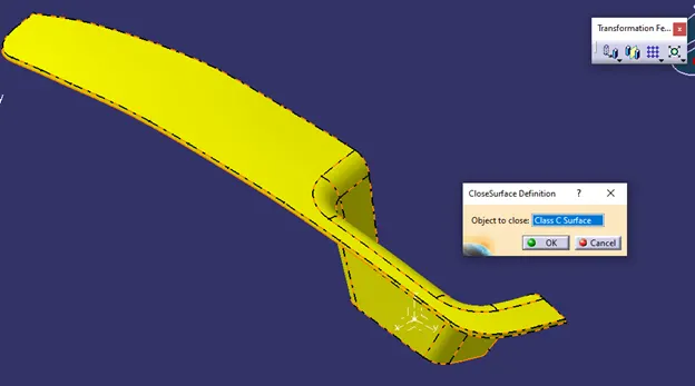
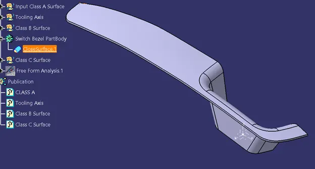
Fig. 40 Solid body of switch bezel
8. Draft Analysis of solid model-
Similar process is used here also.
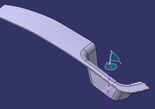
Fig. 41 Alignment of compass
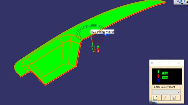
Fig. 42 Draft analysis shows draft angle is 3 degree
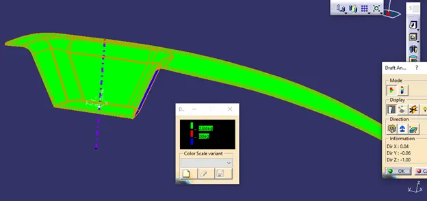
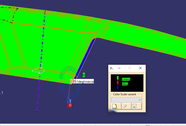
Fig. 43 Draft analysis shows draft angle is 2.8 degree
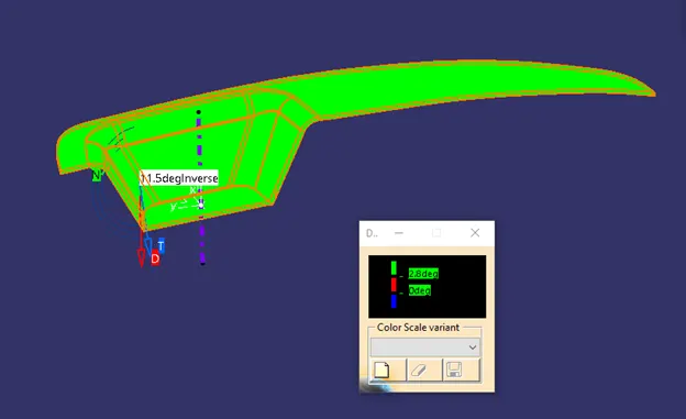
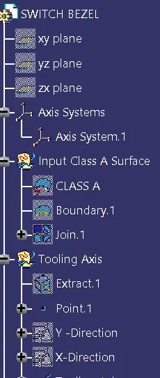
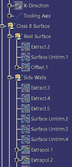
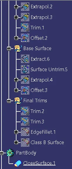
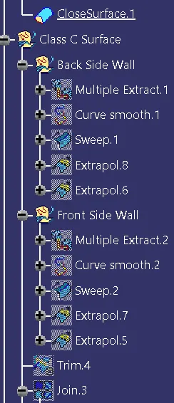
- Screen shots of tree structute, geometrical str. of tooling axis and draft analysis-
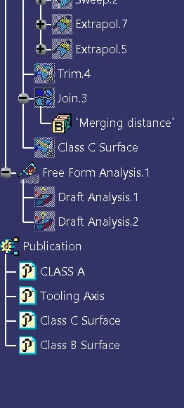
- Screenshots of the model with the proper color code of the draft angle in various orientations (Isometric, Front, Side, and Top View)
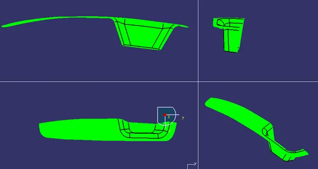
Draft analysis of Class A surfaces in various orientations (Isometric, Front, Side, and Top View)
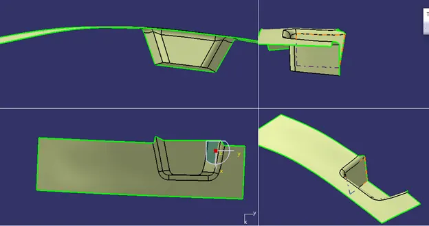
Class B surfaces in various orientations (Isometric, Front, Side, and Top View)
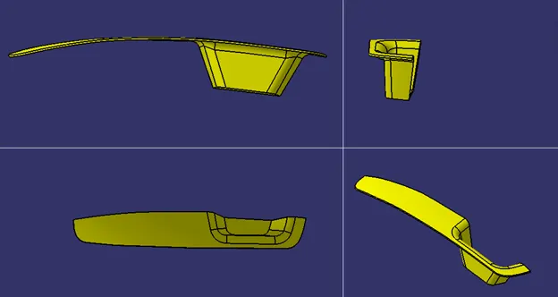
Class C surfaces in various orientations (Isometric, Front, Side, and Top View)
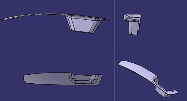
Closed body in various orientations (Isometric, Front, Side, and Top View)
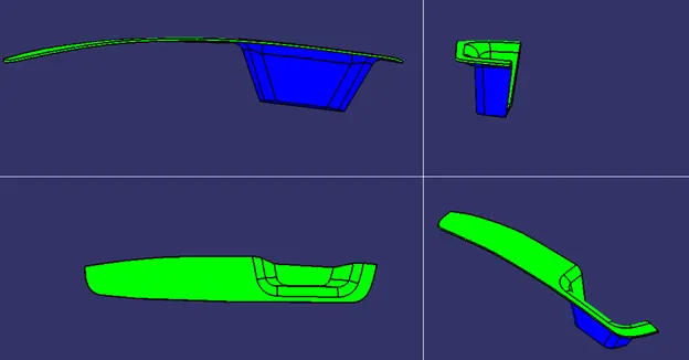
Draft analysis of Closed body in various orientations (Isometric, Front, Side, and Top View)
Conclusion-
by using this challenge we learned -
- to create tooling axis
- to perform draft analysis for surface and solid body with tooling axis
- to create class B and C surface.