Week 8 - Challenge 1 - Draft Analysis on a Fan Cover
Title- Draft Analysis on a Fan Cover
Objective- Create the tooling axis for the given Fan cover model meeting the requirements of the draft angle and perform the Draft analysis on the model.
Explanation / Creating of Tooling axis for the given Fan cover model:-
- Checking Continuity of given fan cover model surface-
First important thing is to check continuity of given class A surface i.e to ensure that class A surface is properly joined or there is no discontinuity in the model. This can be checked by using two options, Join or Boundary feature in CATIA.
Below images are showing that Class A surface has continues connected boundary/ surfaces are joined and it is highlighted by green color line.
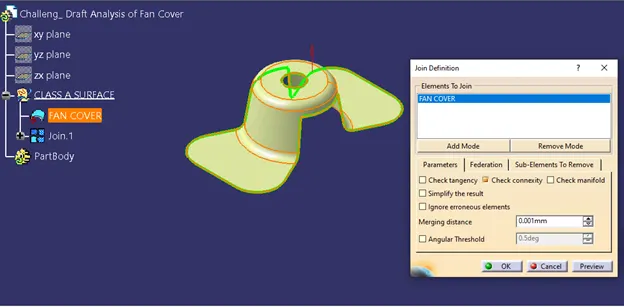
Fig. 1 Fan Cover/ Class A surface has continues join surfaces
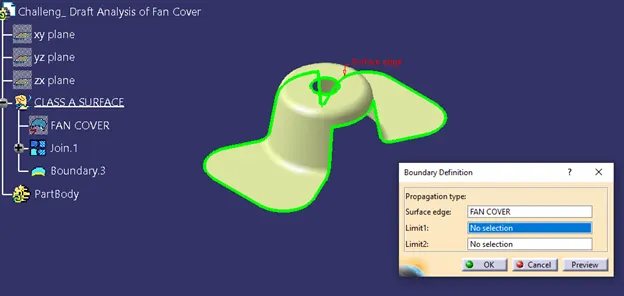
Fig. 2 Fan Cover/ Class A surface has continues connected boundary
- Also we have extracted / disassembled the boundary of Class A surface, so that we can check continuity visually.
- 3 and 4 shows that fan cover model has continuity Class A surface
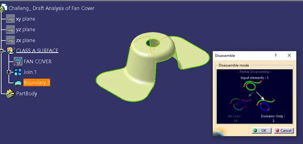
Fig. 3 disassembled the boundary of Class A surface
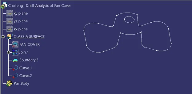
Fig. 4 Extracted boundary is disassembled in to 2 Curves
2. Tooling Axis Direction
- Tooling axis is a direction in which mould/ core and cavity opens. Analyzing model visually to see which direction is most suitable for tooling axis so next Steps is to create tooling axis.
- As we know that fan cover model has hole at top and cutout/slots at side. Now here we have to check the possibility or clearance in all direction of axis and find which surface will create the problems/ difficulty for tooling. Because the surfaces are 90 degree to tooling axis will be cleared, so it is must to check which surface are parallel to the tooling axis.
- From below image we can see that tooling axis along X,Y,Z-direction .
- Tooling axis in X-direction shown in Red color in below image which require two axis / side core for top hole and slot so mold cost gets high.
- Similarly for tooling axis in Y-direction shown in yellow color in below image which is also required two axis.
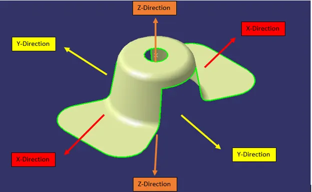
Fig.5 Tooling axis directions
- Procedure for creation of tooling clearing axis in all direction is explained in below-
Cheking possibility or clerance in all direction of axis is done by creating an intersection along an axis on a plane with class a surface/ fan cover model. After that using an intersect we have created two lines contact with the walls using point to point line type. And in the last we got tooling axis by using bisctor of two generated lines. From below fig. we will get idea.
a. Dummy tooling Axis-
Here we have created dummy tooling axis before creation of tooling axis by using line type point – direction. For line creation, point is created and the reference with point a new Axis system is inserted (Not current).
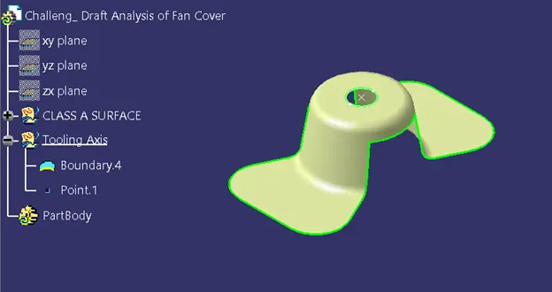
Fig.6 Point is generated for dummy tooling axis
From above fig. 6 we can see that fan cover model has hole at its tops so here we have generated boundary of hole and point w.r.t to center of hole. This generated point is used for further work like generation of axis system, dummy tooling axis, etc. we’ll see in below images.
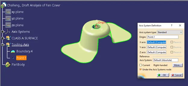
Fig.7 New Axis System is inserted w.r.t Point
- Below fig 8. shows. an intersection of fan cover model on ZX plane, here we get two curves of slots
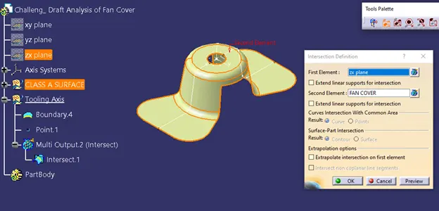
Fig. 8 Intersection of fan cover model in ZX plane.
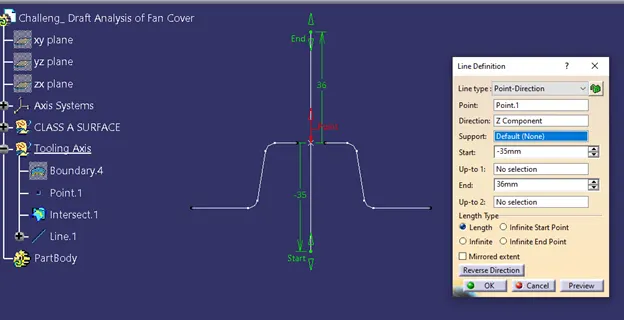
Fig.9. Dummy tooling Axis generated
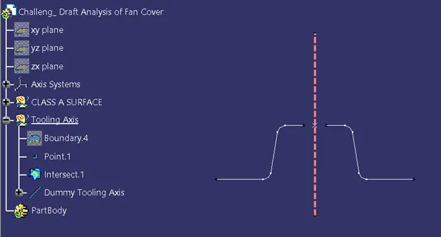
Fig.10 Dummy Tooling Axis Graphic properties are changed just for visualization.
b. Tooling clearing Axis in X direaction -
For tooling clearing axis we have used intersectionof fan cover model/ class A surface which we’ve already created on ZX plane.
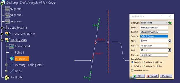
Fig. 11 First Line is created
From above fig. 11 we can see that first an inclined line surface with line type point to point, and this line is created which is parallel to class A surface.
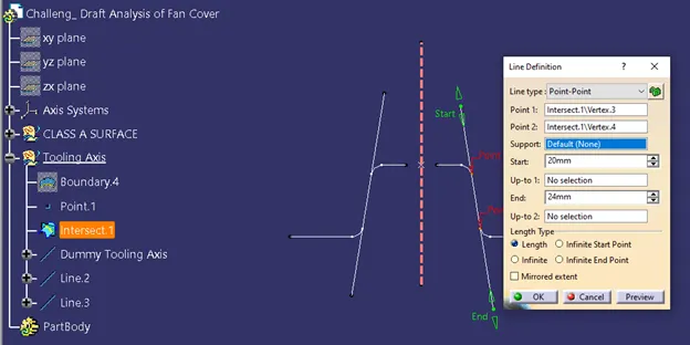
Fig.12 Second line is created
Above procedure is repeated for creation of second line fig. 12.
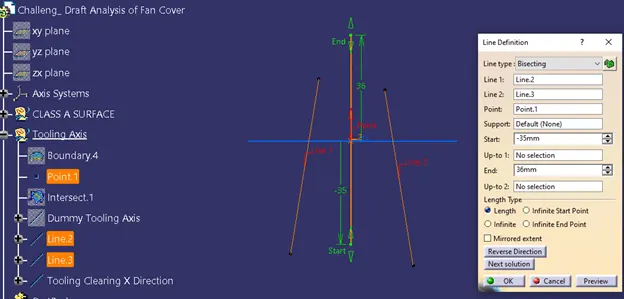
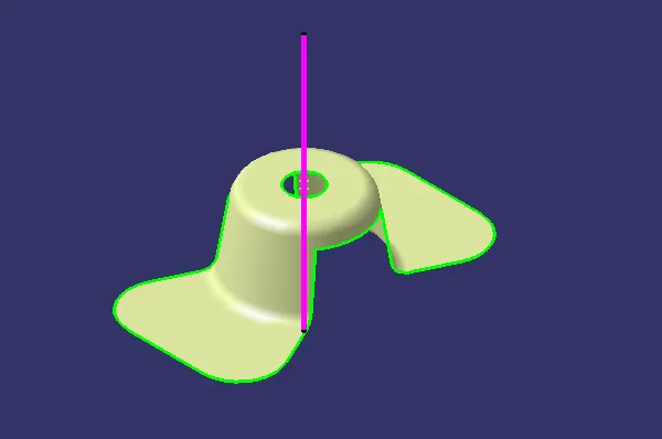
Fig. 13 Tooling Clearing Axis in X Direction
Here above two generated line are used to generate bisection and we got line/ tooling clearing axis in X-direction which is passing through point.Pink color shows ooling clearing axis in X-direction.
c. Tooling Clearing Axis in Y direction-
Below fig 13 shows. An intersection of fan cover model on YZ plane.
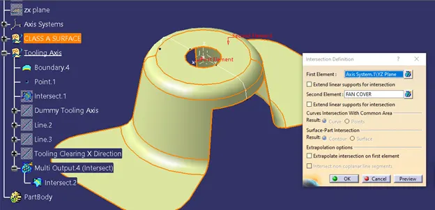
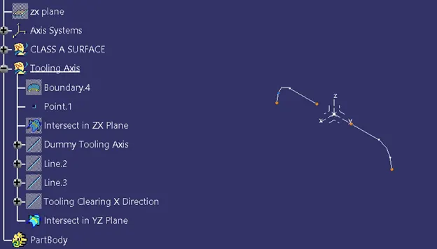
Fig. 13 Intersection in YZ Plane
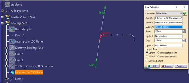
Fig.14 First line is created
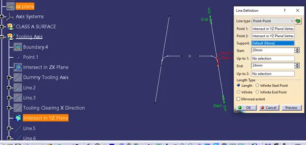
Fig.15 Second line is created
Same procedure of line creation (used in tooling clearing axis in X-direction) is repeated for creation of both line for Y-direction.
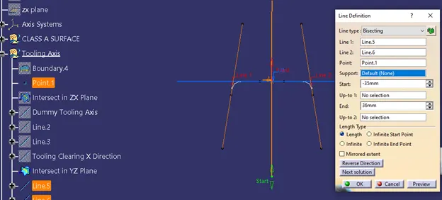
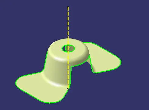
Fig. 16 Tooling Clearing Axis in Y Direction
Here above two generated line are used for bisection and we got line/ tooling clearing axis in Y-direction which is passing through point. Yellow color shows ooling clearing axis in Y-direction.
d. Tooling Axis in Z-direction
As we know that we have two tooling clearing axis i.e in X-direction and Y- direction. Here we have bisected two axis to get our final tooling axis in Z-direction. Final tooling axis is shown in green color.
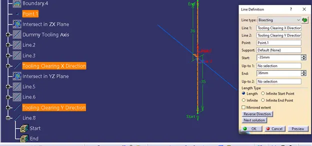
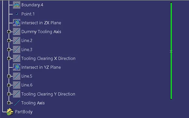
Fig.17 Bisection of tooling clearance axis in X and Y Direction
3. Publication-
Publication feature is used to make easy access of published component (Surface or Sketch), here fan cover and tooling axis is published.
Path- Tools > Publication > Select entity (Surface/ Sketch/Body)
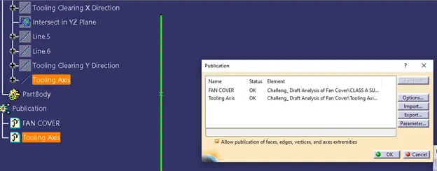
Fig. 18 Fan cover model and Tooling Axis is published
4.Draft Analysis-
The draft allows the part to release or eject from the mold. The draft angle is to reduce the friction between the core, part and cavity, and it’s also for avoid the damage of the core, part and cavity. The minimum draft angle is 0.5 degree but most commonly used draft angle is 3 degree.
Path- Insert > Analysis > Feature Draft Analysis
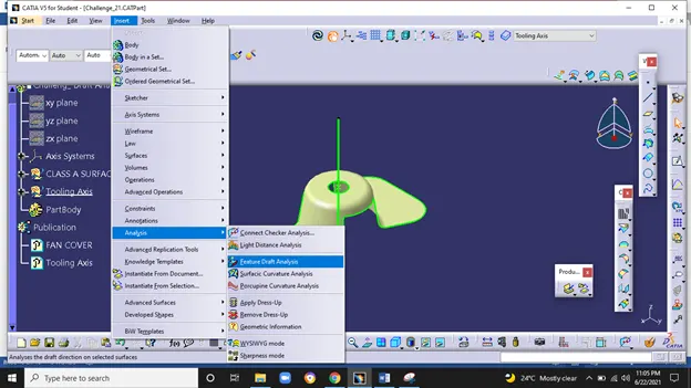
Fig.19 Path for draft Analysis
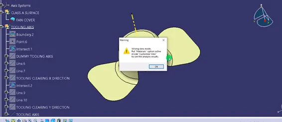
Fig.20 Warning View mode
Above fig.20 show warning that means we have to make sure that before switching to draft analysis part should be in customer view parameter with material option of mesh.
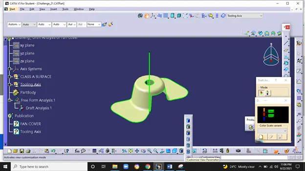
Fig.21 Customer View Parameter
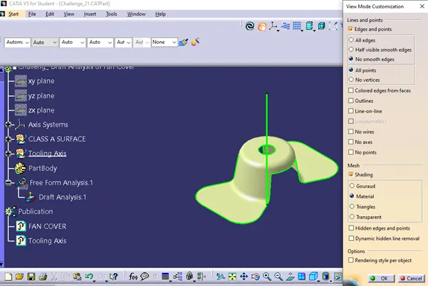
Fig. 21 Material Mode in Customer View Parameter
Next step is to align the tooling axis with class A surface by clicking on compass icon and drag it to tooling axis.
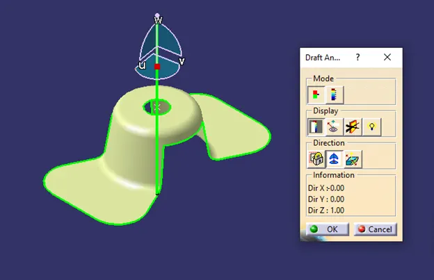
Fig.22 Alignment of tooling axis
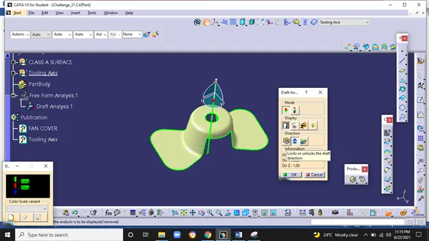
Fig.21 Lock the draft direction
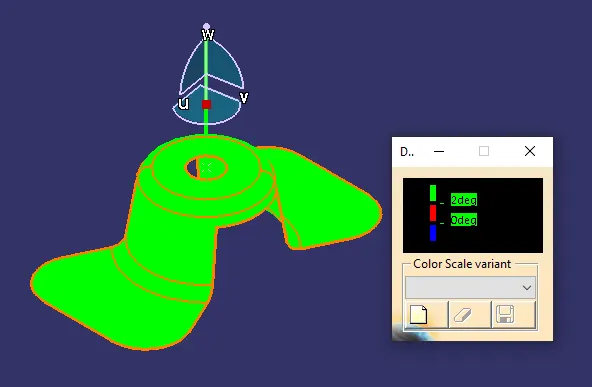
Fig.22 Surface with 2 degree of draft
After clicking on class A surface we get green color surface shown in fig. 22 which means that surface has more than 2 degree of draft.
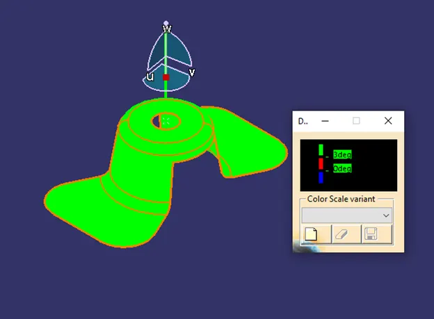
Fig. 23 Surface with 3 degree of draft
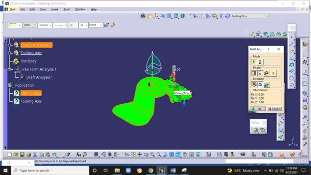
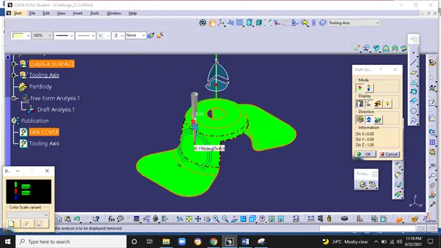
Fig. 24 Draft at various location
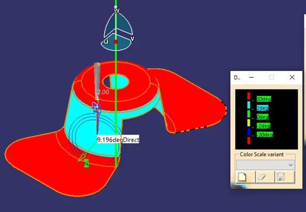
Fig.25 Full Analysis mode of draft
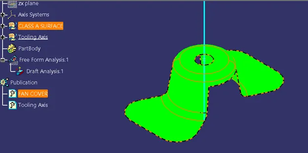
Fig. 26 Isometric View with draft Analysis
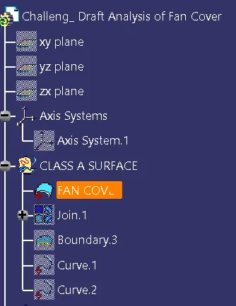
- Screen shots of tree structute, geometrical str. of tooling axis and draft analysis-
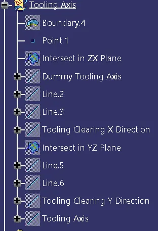
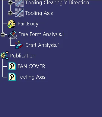
- Screenshots of the model with the proper color code of the draft angle in various orientations (Isometric, Front, Side, and Top View)
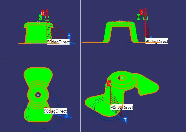
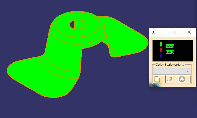
Fig.27 Isometric View with draft angle 3Degree
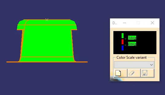
Fig.28 Front View with draft angle 3Degree
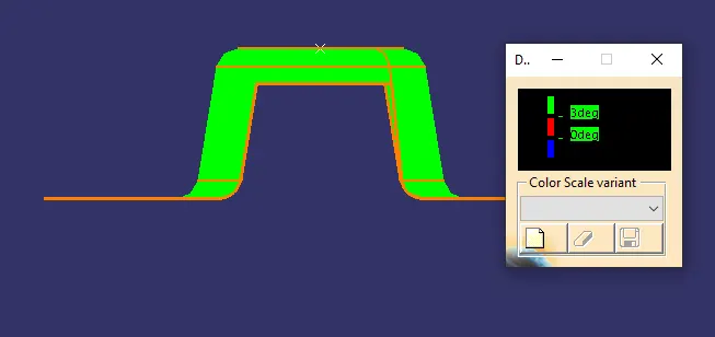
Fig.29 Side View with draft angle 3Degree
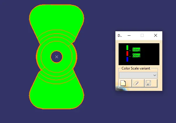
Fig.30 Top View with draft angle 3Degre