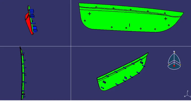
Week 9 - Project 1 - Door Applique Design with Engineering Features
Title- Project 1 - Door Applique Design with Engineering Features
Objectives-
- To create class B and C surface from given class A surface.
- To create the tooling axis for the given Class-A Surface and it should be created to meet the requirements of the draft angle
- To create the Base Bracket Plastic component through the given Class-A surface.
- To perform the Draft analysis on the model.
- Create the Heat Stakes and the locators considering the design rules.
- To publish class A,B,C surfaces, Tooling axis and side core axis.
Introduction-
- This report demonstrate the design door applique automotive plastic part with industry principle like determine and implementation of tooling axis, draft analysis, draft angle, creation of class B and C surfaces, heat stakes, 2 and 4 way locators, etc.
- The plastic component is designed with surface and part design technique in CATIA.
Methodology-
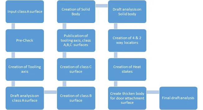
Terms definition-
- Tooling axis/direction-
- For this model tooling axis is created along Y axis as the direction perpendicular of the normal to the applique surface falls along Y axis.
- Class A surface-
- The surface is made by designer and surface design is given to us to work on it. It is aesthetic surface and the outer most surface.
- Class B Surface-
- This surface is below a thickness value of 2.5mm from class A surface. It contains engineering aspects of a model.
- Class C Surface-
- A class C surface that join class- A and Class B surface and it is created with proper draft angle with tooling direction.
- Solid body creation-
- The solid body is created using created class A,B and C surface. Once the shell is created then it is changed into a solid body with close surface command in part modelling.
- Draft Analysis-
- The Draft Analysis command enables you to detect if the part you drafted will be easily removed. This type of analysis is performed based on color ranges identifying zones on the analyzed element where the deviation from the draft direction at any point, corresponds to specified values.
- Locators / Locator pins-
- This are rib likes structure on class B surface of plastic component which is used to position the child part with parent part while assembly.
- These locators were placed in the multiple location on the part depending upon the degree of freedom which needs to be arrested.
- There were classified as 2 way and 4 way locators .The one which is in “+” like structure is the four way locator and the one which is “-” like structure is the two way locator.
- Locators are used to locate a component to arrest its DOF using 3-2-1 principle which is arresting of 3DOF’s first then 2DOF’s and finally 1 DOF in as sequence.
- Both these locators use the same rib design rule and principle.
- Heat Stakes-
- In manufacturing products with thermoplastic components, it is often necessary to join a thermoplastic to a part having dissimilar material such as a metal or any other thermoplastic.
- Heat stakes is an assembly method that uses the controlled melting and reforming of plastic stud or boss to capture or lock another plastic or metal component of assembly in place.
- The plastic stud protrudes through a hole in the component to be locked in place.
- Heated thermal tips are used to melt the top of the studs which fills up the volume of the cavity to produce a head locking the component in place.
- The progressive melting of plastic under continuous pressure forms the head.
- When staking, the right combination of heat and pressure is critical.
- In short locators locate the component and lock11 DOF whereas the heat stakes is a fixation which lock the final DOF.
- Heat stakes are the vertical cylindrical structures added to the class B surface. These are used to attach the child part with parent part.
- This kind of attachment provides advantage of avoiding any additional fastening methods like bolting, push clips, etc. Which will add the weight of the component.
- Disadvantage of heat stake is once it’s fixed it cannot be removed without damaging the component.
Design Requirements-
- Though they have different name based on the application, in general they are ribs. We will be following the design rules which are followed for the ribs to avoid the sink marks and short shots. Some of design considerations are explained as bellow-
- Rib thickness-
- It should be maximum 40% of component wall thickness.
- This is used to avoid sink marks on the visible surface.
- It the thickness of rib is high at base then it will increase thickness at the junction therefore this will retain more heat than other surface.
- Due to this when it cools slowly and it will try to shrink the material at outside region and sink mark will generate on flat surface.
- Rib thickness at top-
- It should be at least 0.75mm so that molten material can flow easily.
- Is the thickness at the top is reduced, it becomes difficult for the molten metal to reach at corner of rib as they are almost perpendicular to flow direction. This will leave unfilled mold region which caused defect called as short shots.
- Rib Height-
- It must be less than the 5 times of wall thickness
- Rib base fillet radius-
- It should be 0.125 times of wall thickness and maximum is 0.25mm is allowed.
- Rib root thickness-
- It should be maintained between 1.75 to 3.25 mm
Step-1 Input class A surface-
- The surface is made by designer shown in fig.2 and surface design is given to us to work on it. It is aesthetic surface and the outer most surface.
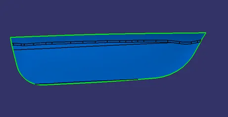
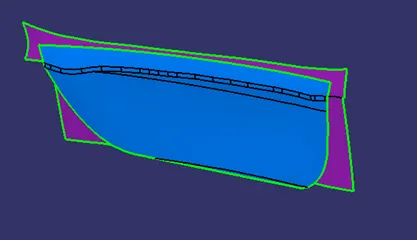
Fig.2 Class A surface
Step-2 Pre-check of class A surface-
- To ensure that class A surface is properly joined or there is no discontinuity in the model. This can be checked by using two options, Join or Boundary feature in CATIA. Check for any opening in the given model of door applique by using boundary.
- Path- Boundary>Select surface to create the boundary at the openings of component.
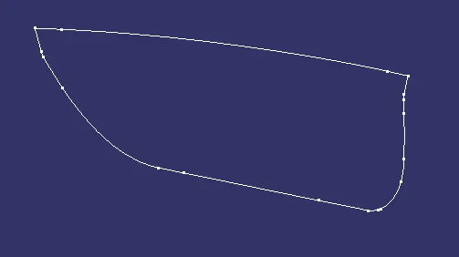
Fig.3 Boundary of class A surface
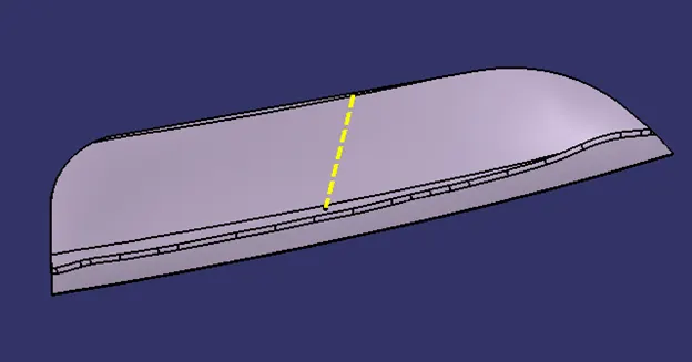
Step-3 Tooling Axis
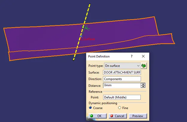
- Create a point at the center of surface by using point definition by- Point Type- on surface, Surface- select the surface and Distance- 0mm.
- Create ling a long y direction which will be our main tooling axis, by using line definition option- Line Type- Point-Direction, Point- Select the created point and Direction- Y. Tooling axis shown in fig.4.
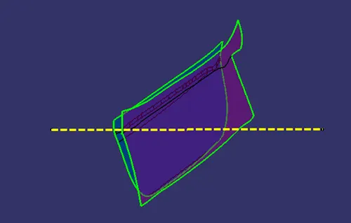
Fig. 4 Tooling axis for class A surface
Step-4 Draft Analysis for class A surface-
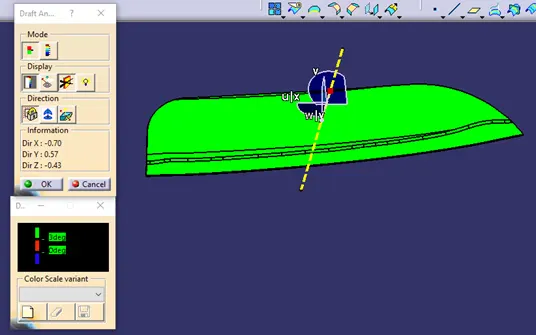
- It is a tool in CATIA which identifies the zones which deviates from the specified values of angles along a defined draft direction using color codes.
- It highlights the regions of draft using colors.
- Draft analysis is the first step performed after receiving the class A of the component.
- It should be passed in order to make the plastic component ready for manufacture.
- Acceptable draft angle are used as range for draft analysis.
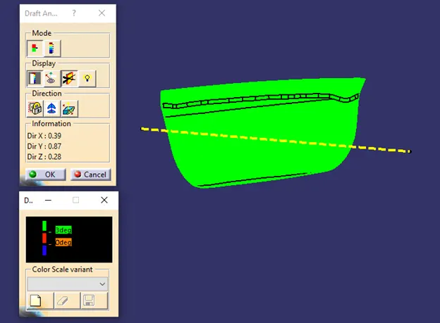
Fig. 5 Draft analysis on class A surface
Step-5 Creation of class B surface-
- Extract the class A surface by selecting the surface to extract.
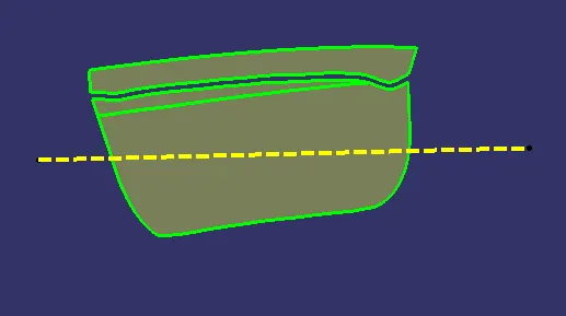
- Untrim the extracted surfaces and join the surface.
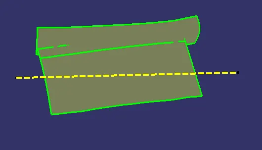
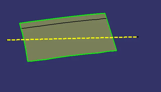
- Trim the joined surface and untrimed surface together. Extrapolate the trimmed surface.
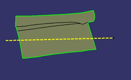
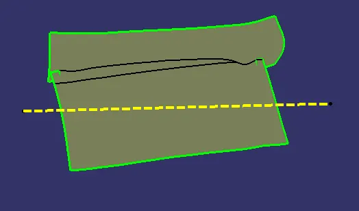
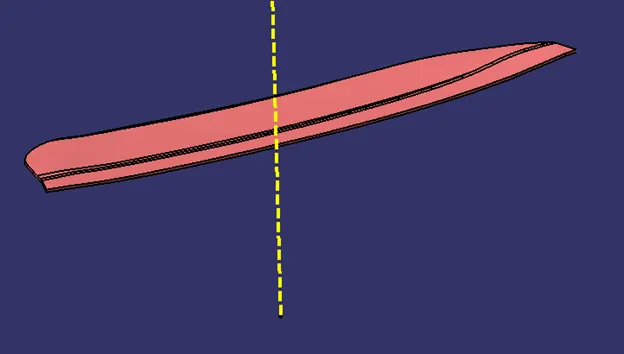
- Offset the extrapolated surface by selecting the surface to offset to a distance 2.5 mm and then apply edge fillet of R12.5mm. Pink color surface shows the final class B surface.
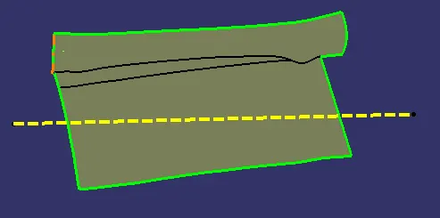
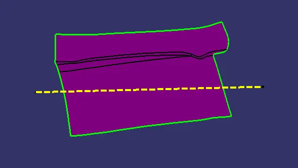
Step-6 Class C surface-
- Extract the class A surface boundary and make the curve as smooth curve.
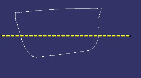
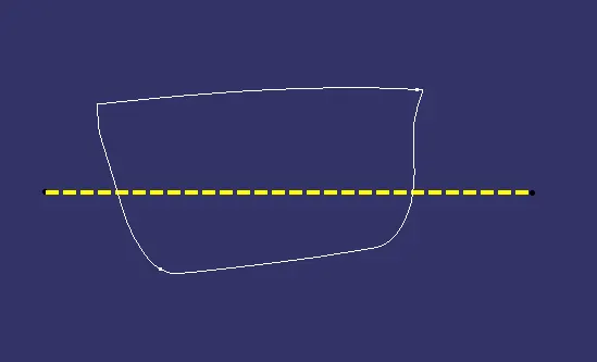
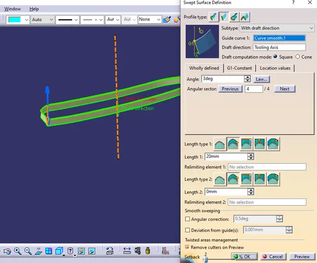
- Use sweep surface command to extrude the boundary using the “with draft direction” option and selecting the boundary for guide curve and the tooling axis as draft direction.
- Use draft angle as 3° and select outward direction with length value.
- Join class A surface and swept surface together.
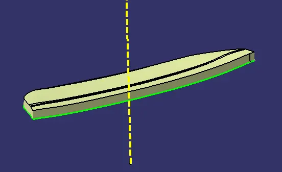
- Trim class B surface and joined surface together then we will get our final class C surface.
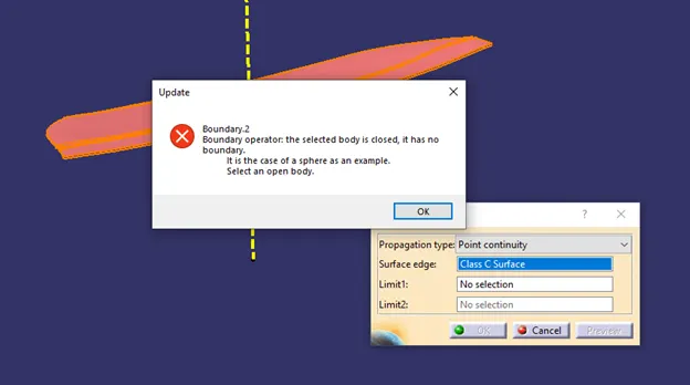
- Class C surface has closed shell surface, no boundary is there.
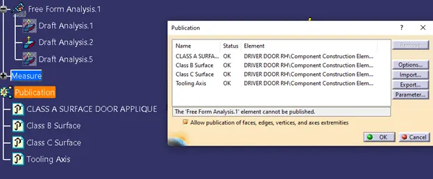
Step-7 Publication
- This feature is used to make easy access of published component (Surface or Sketch).
- Here parting line and surface, core and cavity block are published.
- Path- Tools > Publication > Select entity (Surface/ Sketch/Body)
Step-8 Creation of Solid Body
- Convert class C surface in to closed surface using part modelling.
Step-9 Draft analysis on Solid body
- The Draft Analysis command enables you to detect if the part you drafted will be easily removed. This type of analysis is performed based on color ranges identifying zones on the analyzed element where the deviation from the draft direction at any point, corresponds to specified values.
Step-10 Creation of locators-
- Create a point on surface using point definition – on surface, as distance 0mm.
- Create a new plane by using plane type- parallel throught point. Plane should be parallel to ZX plane through created point.
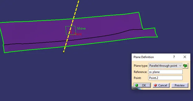
- Create a sketch on created plane for 4 way locators.
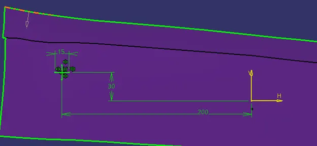
- Pad the sketch in part design and thicken the sketch using neutral fibre thick option. Use design principle rule – thickness should be 40% of the component wall thickness.
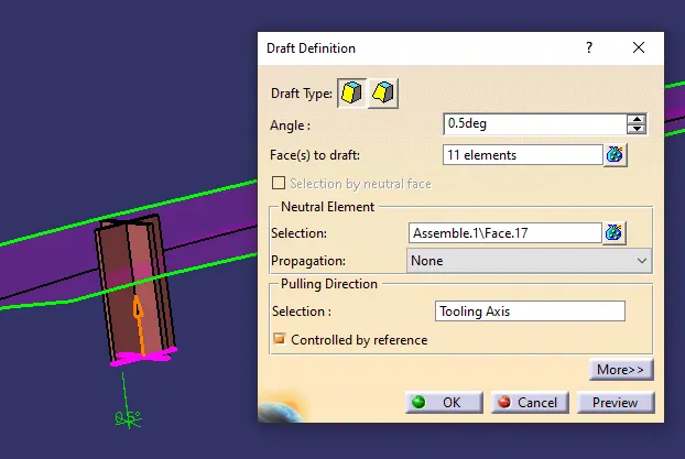
- Apply draft of 0.5° on vertical surfaces of padded body, Neutral surface- base surface of body , pulling direction- tooling axis.
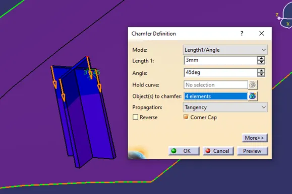
- After drafting the faces, chamfer the edges at the top upto length 3mm at 45°.
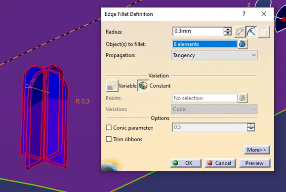
- Apply edge fillet of radius 3 mm and 0.3 mm to the faces of locator.
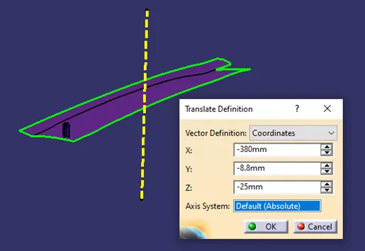
- To make same 4 way locator at different location, copy the part body of 4way locator and paste as a special reference link and then translate w.r.t co-ordinate values.
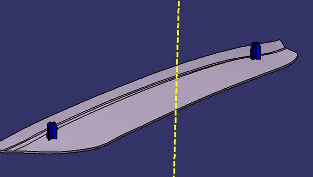
- For creation of 2 way locator, follow same process explain above. Here only difference is in sketch, make “-” like sketch, pad the sketch with thicken value, draft the padded body face and apply chamfer and fillet edges of body.
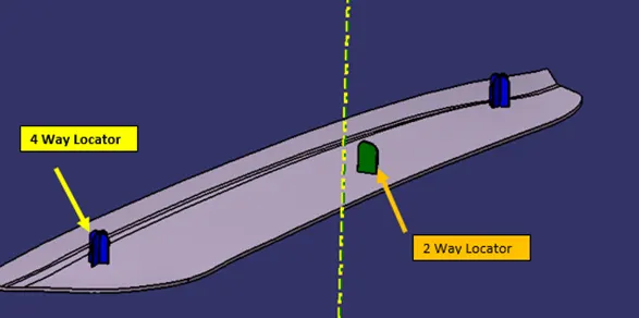
- By Boolean operation, union trim the 4 way and 2 way locators with the solid body of door applique by selection the faces to keep.
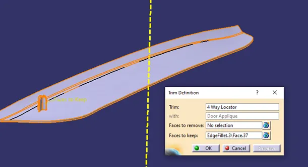
Step- 11 creation of heat stakes-
- Offset the class A surface to 2.5 mm and extract the boundaries of the offsetted surface.
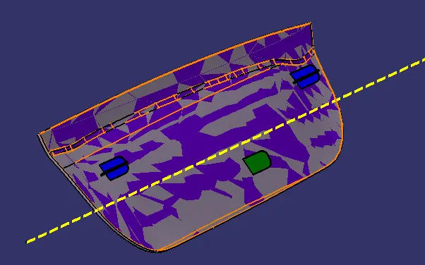
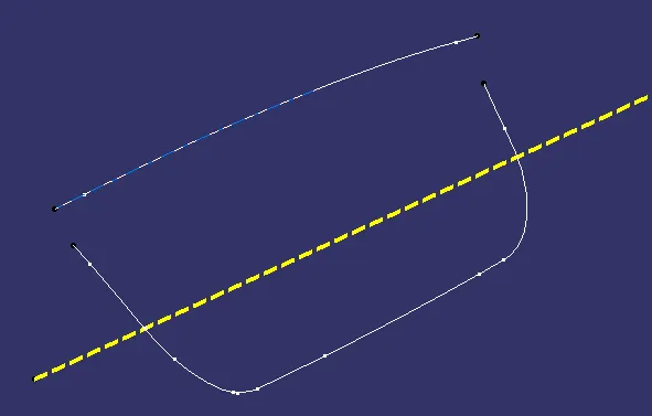
- Parallel curve the extracted boundaries by parallel curve definition: curve- extracted boundary, support- surface, constant- distance.
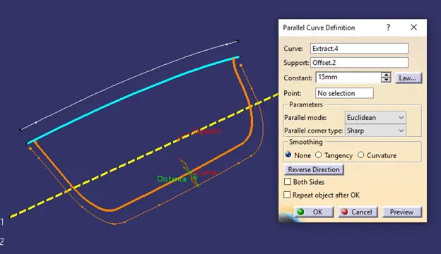
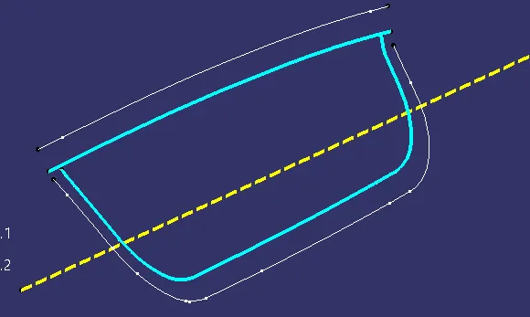
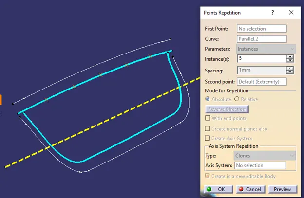
- Make points on the both parallel curves at instances using point by repetition.
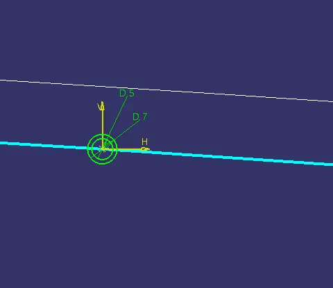
- Create a sketch on created plane with created point and pad it up to class A surface.
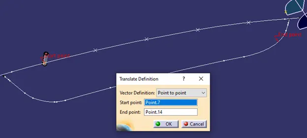
- Copy the heat stake part body and paste as special with reference link and replicate to the created points by sing translate option. Here use point to point translate for creation of heat stake at created points.
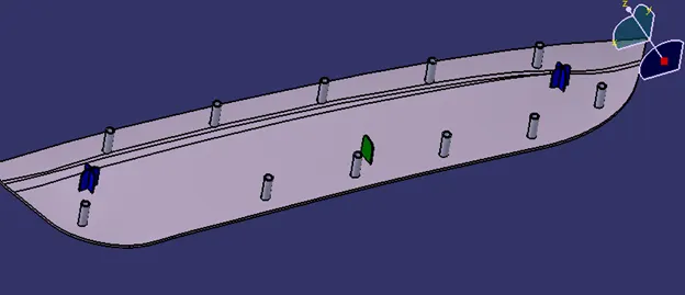
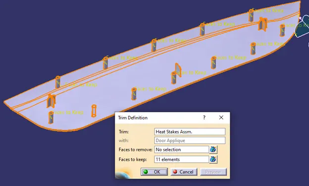
- By Boolean operation, union trim the created heat stakes body with the solid body of door applique by selection the faces to keep. The distance between the tip surface of locator and door attachment surface should be equal for all locators. Also the height of heat stake should be smaller than the locators.
Step-12 Thicken the door attachment surface and creating clearance for locator and heat stakes.
- Thicken the door attachment surface by thicken option in part design by selection the surface to thicken to 2.5 mm.
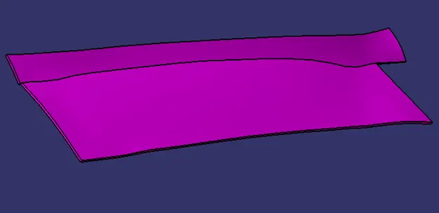
- Now from the locator and heat stake geometrical set, copy the sketch of 4 and 2 way locator, heat stake and paste in to a geometrical sketch of counterpart clearance and edit the sketch by changing circle of dia.14.7mm.
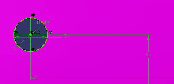
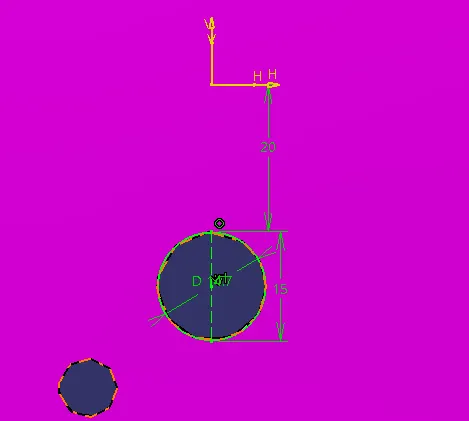
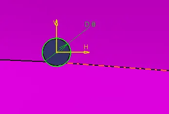
- Pad the sketch below the door attachment body and apply draft of 0.5° to the outer surface of padded body.
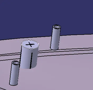
- By Boolean operation, remove the padded body from the thicken surface. So clearance gap between-
- Locator wall and clearance wall should be 0.1 mm to lock the motion.
- Clarence wall and heat stake should be 0.5mm
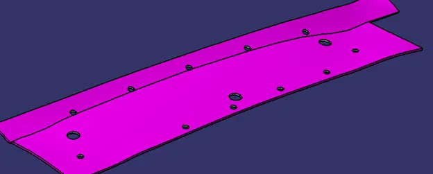
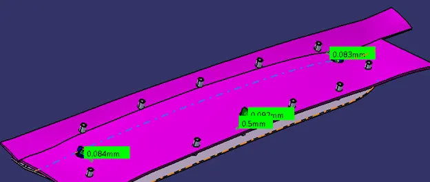
Step- 13 Draft analysis for final part
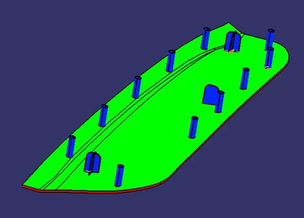
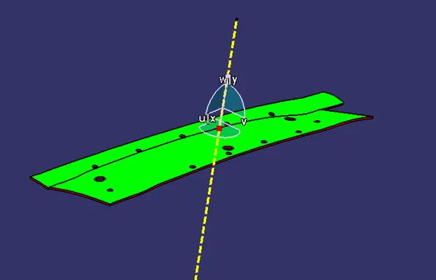
Conclusion-
- The class B and C surfaces are created from given class A surface.
- The tooling axis for the given Class-A Surface is created and draft analysis is performed on class A surface.
- The Base Bracket Plastic component is made through the given class C surface and draft analysis is also performed.
- The heat stakes and the 4,2 way locators are created by considering the design rules.
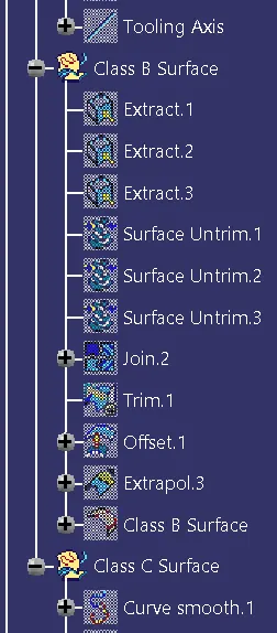
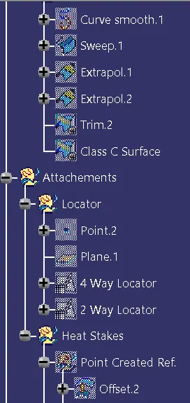
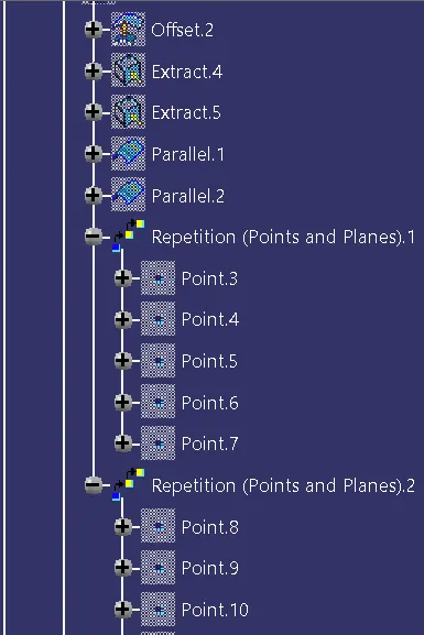
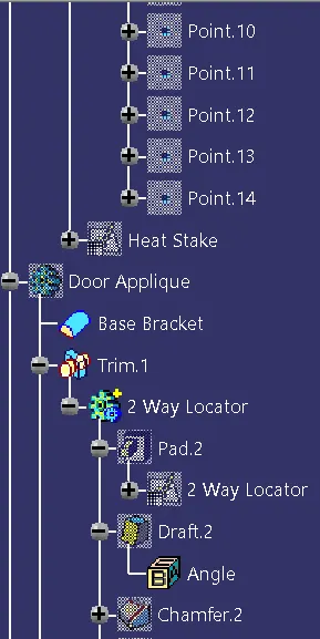
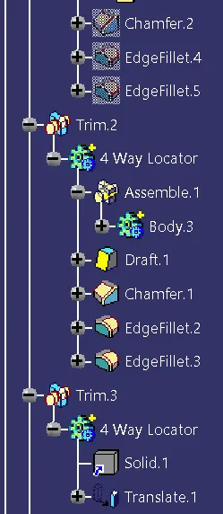
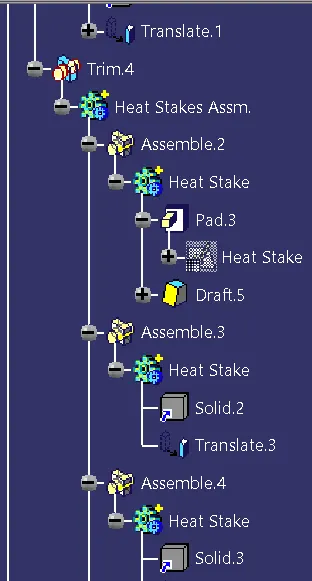
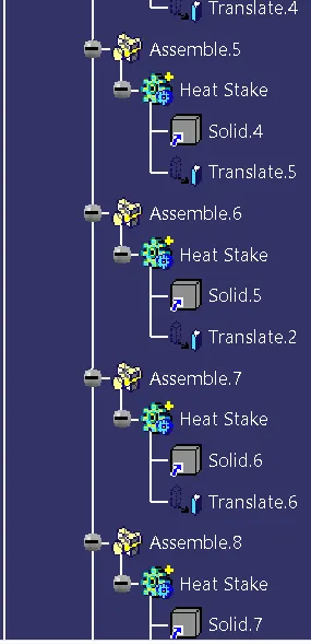
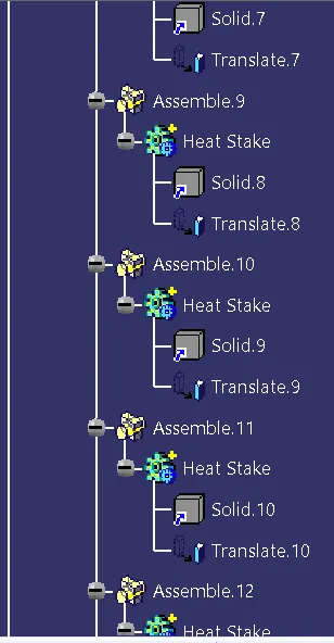
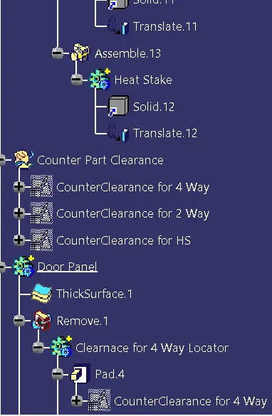
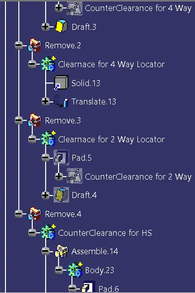
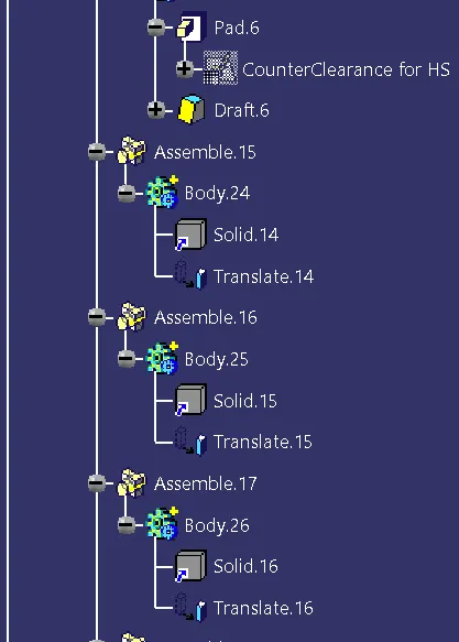
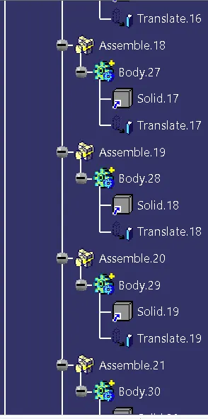
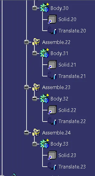
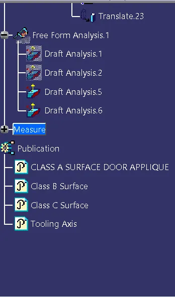
- Screenshots of the tree structure for completed design
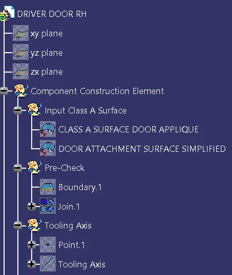
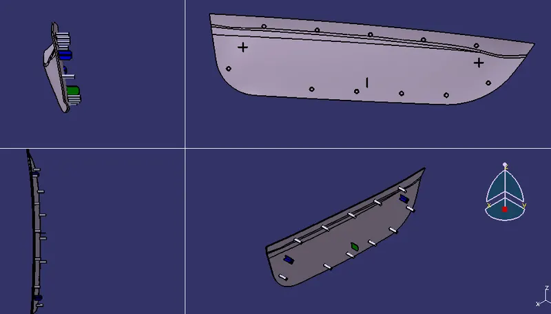
- Screenshots of the completed design in various orientations (Isometric, Front, Side, and Top View)
- Design of door applique in various orientations
- Design of door attachment in varioue orientation
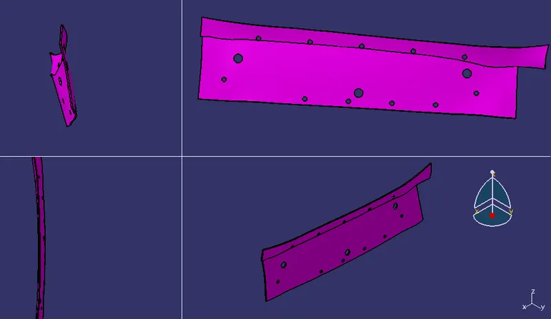
- Draft analysis of door attachment in various orientations
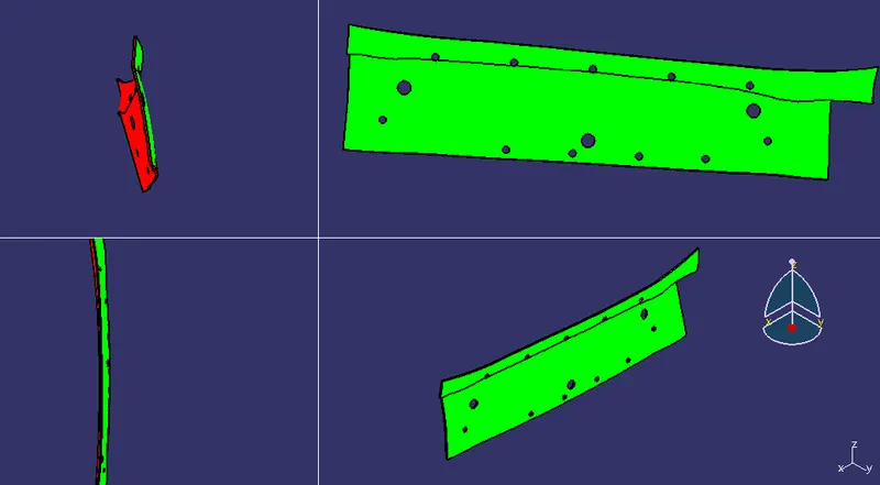
- Draft analysis of door applique in various orientations