Week 8 - Challenge 2 - Base Bracket Design
Title- Challenge 2 - Base Bracket Design
Objectives-
To create the Base Bracket Plastic component through the given Class-A surface. To begin with, the tooling axis for the given Class-A Surface created meeting the requirements of the draft angle and at the end the Draft analysis is perfomed on the model.
Detailed Explanation-
- Class A surface- Asurface is made by designer and surface design is given to modeler to work on it. It is aesthetic surface and the outer most surface.
- Class B Surface- A surface which is below a certain thickness from class A surface is called as class B surface. It contains engineering aspects of a model.
- Class C Surface- A class C surface that join class- A and Class B surface.
Methodology-
For the model of Base Bracket Plastic component, we will follow below methodology-
- Checking Continuity of given model surface
- Tooling Axis
- Draft Analysis
- Class B –Surface
- Class C- Surface
- Publication
- Solid Body creation from surface.
Extensively used tools for base bracket surface creations are-
- Intersection
- Extract
- Un trim
- Join
- Trim
- Extrapolate
- Offset
- Boundary
- Line, Point
- Sweep
- Trim
- Edge Fillet
- Close Surface
Methodology in detailed for creation of class B and C surface are -
1. Checking Continuity of given model surface:-
- First important thing is to check continuity of given class A surface i.e to ensure that class A surface is properly joined or there is no discontinuity in the model. This can be checked by using two options, Join or Boundary feature in CATIA.
- Below images are showing that Class A surface has continues connected boundary/ surfaces are joined and it is highlighted by green color line.
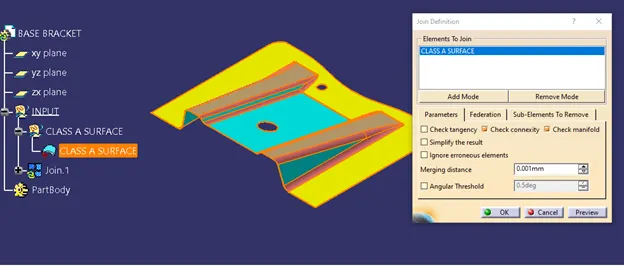
Fig. 1 Joined Class A surface
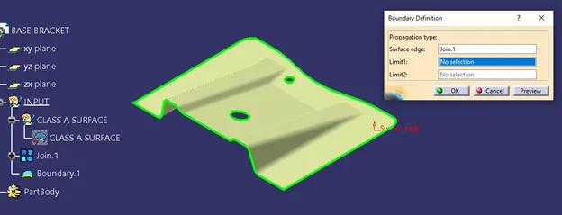
Fig. 2 Boundary of Class A surface
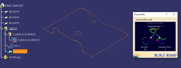
Fig.3 Dis-assembled boundaries for class A surface
- Fig.1 and 2 shows that base bracket class A surface has continuity Class A surface
- Tooling Axis
- Tooling axis is a direction in which mould/ core and cavity opens. Analyzing model visually to see which direction is most suitable for tooling axis so next Steps is to create tooling axis.
- Now here we have to check the possibility or clearance in all direction of axis and find which surface will create the problems/ difficulty for tooling. Because the surfaces are 90 degree to tooling axis will be cleared, so it is must to check which surface are parallel to the tooling axis.
- As we know that model has 2 holes at top. So we can directly take tooling axis perpendicular to holes. Here FV and TV, we have to keep it in mind while choosing tooling axis.
- From below image we can see that tooling axis along X,Y,Z-direction .
- Tooling axis in X-direction shown in green color in below image which require two axis / side core for top hole and slot so mold cost gets high.
- Similarly for tooling axis in Y-direction shown in orange color in below image, in which we cannot see holes.
- Tooling axis in Z-direction shown in light blue color in below image, here we can see 2 holes and surface also. So we will consider it as final tooling axis.
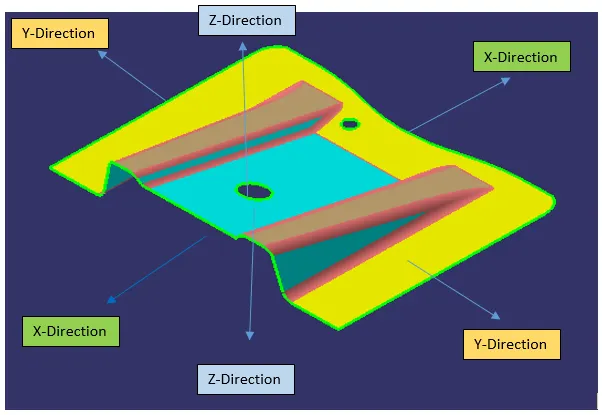
Fig.4 Tooling axis directions
Dummy Tooling Surface-
- Here we have created dummy tooling axis before creation of tooling axis by using line type point – direction. For line creation, point is created and the reference with point a new Axis system is inserted (Not current).
- Procedure for creation of dummy tooling axis is explained in below-
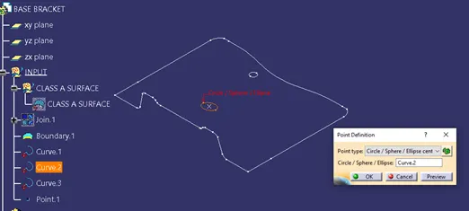
Fig.5 Point is created
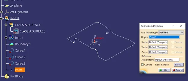
Fig. 6 Axis system is inserted with point 1
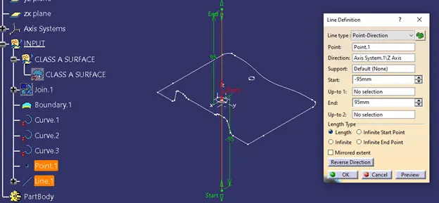
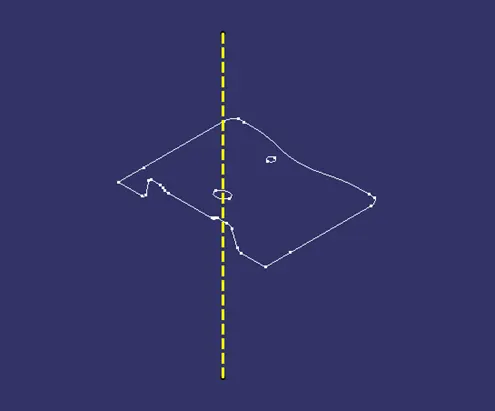
Fig.7 Dummy tooling Axis generated
- Below fig. 8 an intersection of class A surface on YZ plane. Form plane YZ we can see both side surfaces.
- Here we’ve taken intersection of class A surface on YZ plane get two curves.
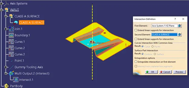
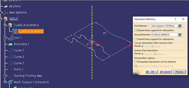
Fig. 8 Intersection of class A surface.
- Create a line from intersected surfaces. Consider inclined line points to create is line by point to point type on both side.
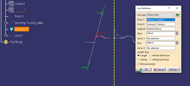
Fig.9 First Line created
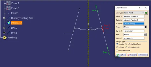
Fig.10 Second Line created
- Here above two generated line are used to generate bisection and we got line/ tooling clearing axis in Z-direction which is passing through point. And this is our final tooling axis.
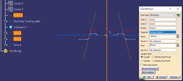
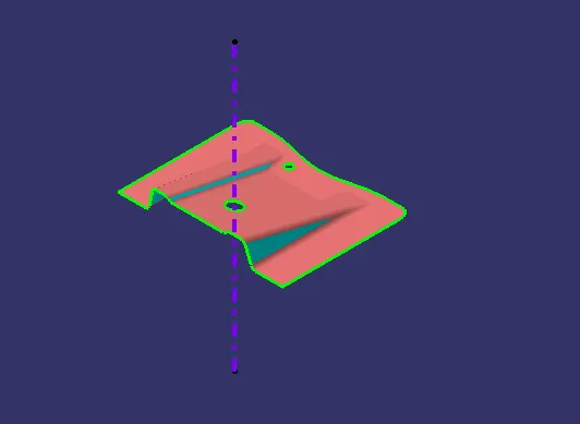
Fig.11 Tooling Axis
- Draft Analysis
The draft allows the part to release or eject from the mold. The draft angle is to reduce the friction between the core, part and cavity, and it’s also for avoid the damage of the core, part and cavity. The minimum draft angle is 0.5 degree but most commonly used draft angle is 3 degree.
Path- Insert > Analysis > Feature Draft Analysis
Make sure that before switching to draft analysis part should be in customer view parameter with material option of mesh.
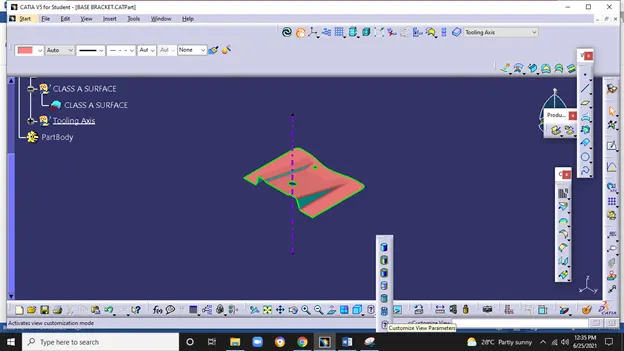
Fig. 12 Customer View Parameter
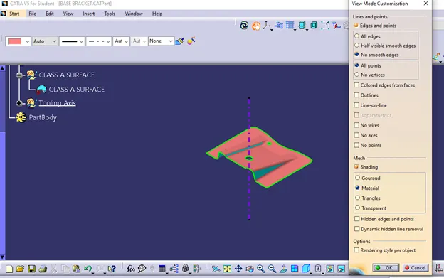
Fig. 13 Material Mode in Customer View Parameter
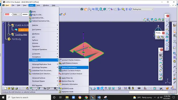
Fig. 14 Path for draft Analysis
Next step is to align the tooling axis with class A surface by clicking on compass icon and drag it to tooling axis
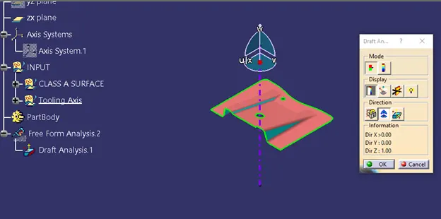
Fig.15 Alignment of compass
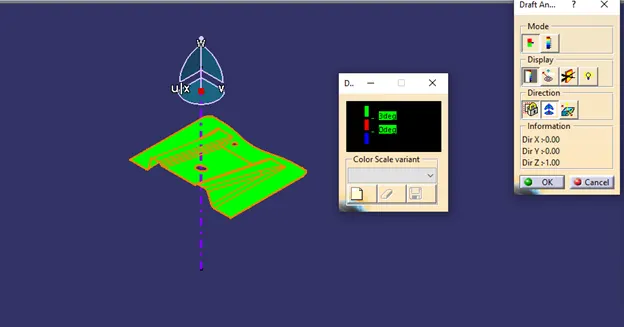
Fig.16 Lock the draft direction
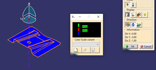
Fig.17 Inverse the draft
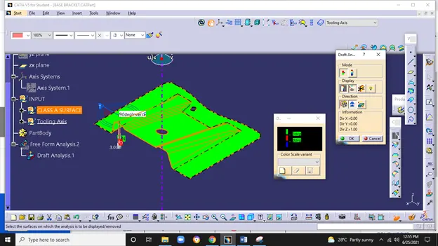
Fig. 18 Draft 3 degree at various orientation
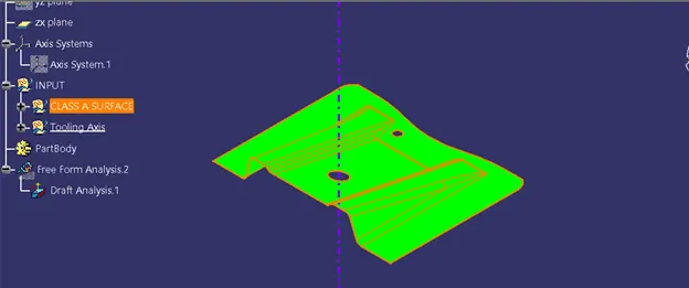
Fig.19 Draft Analysis in Iso metric View
4. Class B surface-
Here we have to divide the surfaces as mention below and work on them one by one.
- Pink Color- 2 (Base Surfaces)
- Sky Blue Color- 6 (Right side - Rib 1 and Left side - Rib 2)
note- Rib 1 consist of 3 surfaces and rib 2 consist of 3 surfaces
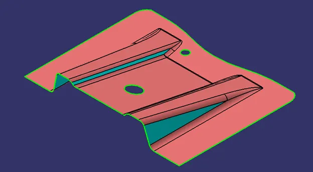
Fig.20 Division of class A surface
1. Rib 1
Extract right side 3 sky blue color surface one by one.
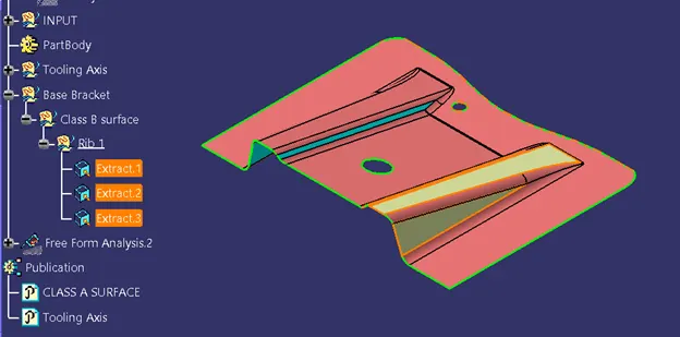
Fig. 21 Extracted 3 Surfaces for rib 1
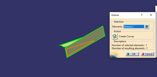
Fig. 22 Untrim the extract 3 surfaces for rib 1
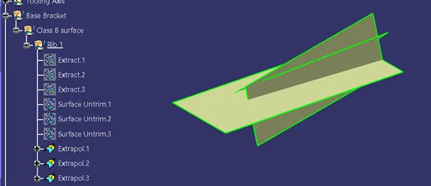
Fig.23 Extrapolated the untrimmed 3 surfaces for rib 1
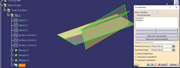
Fig. 24 Trim the extrapolated 1 and 2 surfaces
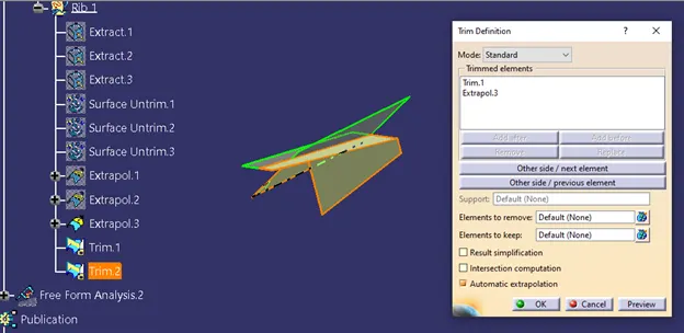
Fig. 25 Trim the trim 1 and 3 surfaces
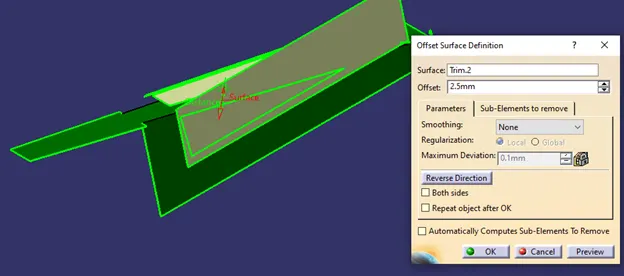
Fig.26 Offset the trim 2 @ 2.5 mm shown in green color
2. Rib 2
Extract left side 3 sky blue color surface one by one.
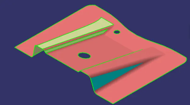
Fig. 27 Extracted 3 Surfaces for rib 2
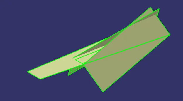
Fig. 28 Untrim the extract 3 surfaces for rib 2
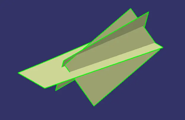
Fig.29 Extrapolated the untrimmed 3 surfaces for rib 2
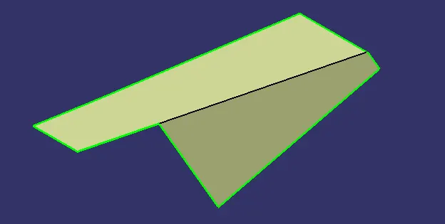
Fig. 30 Trim the extrapolated 4 and 5 surfaces
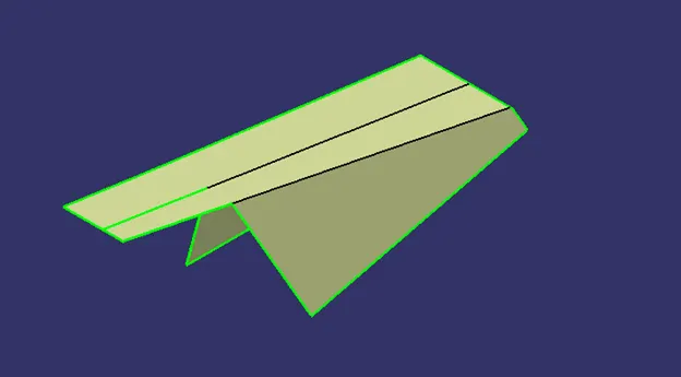
Fig. 31 Trim the extrapolated 6 and trim 2 surfaces
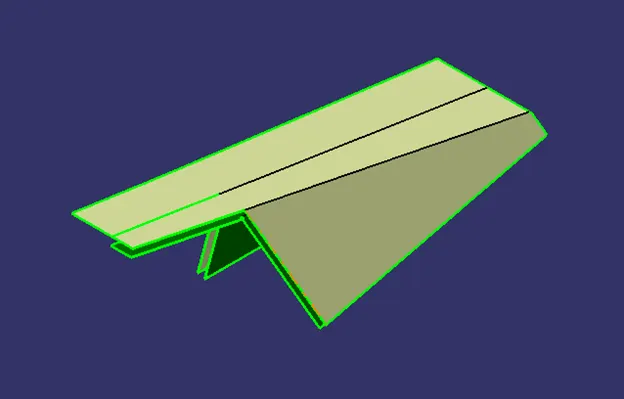
Fig.32 Offset the trim 4 @ 2.5 mm shown in green color
3. Base Surfaces-
Extract pink surfaces.
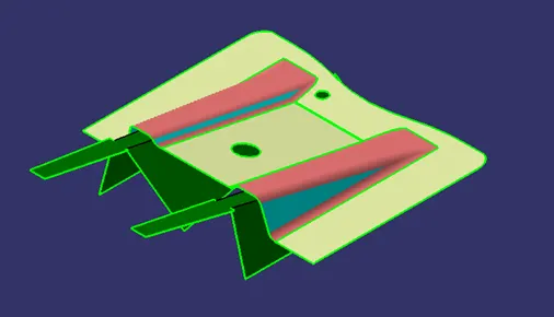
Fig.33 Extract pink surfaces.
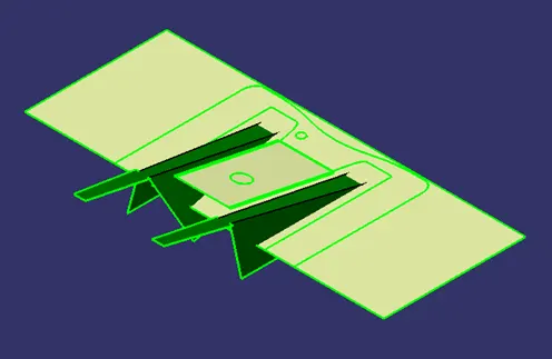
Fig.34 untrimmed the base surfaces
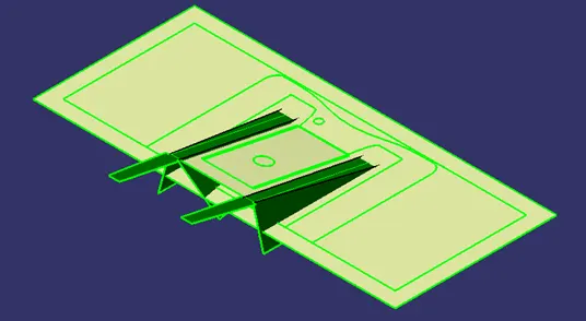
Fig. 35 Extrapolate the base surface
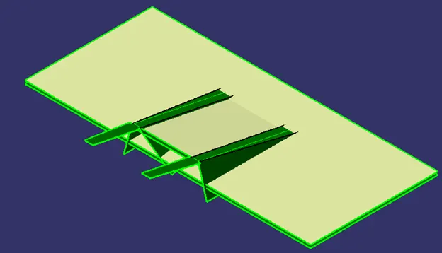
Fig.36 Offset the base surfaces @ 2.5 mm shown in green color
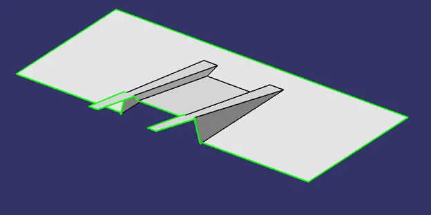
Fig.37 Final trim of rib 1, 2 and base surface
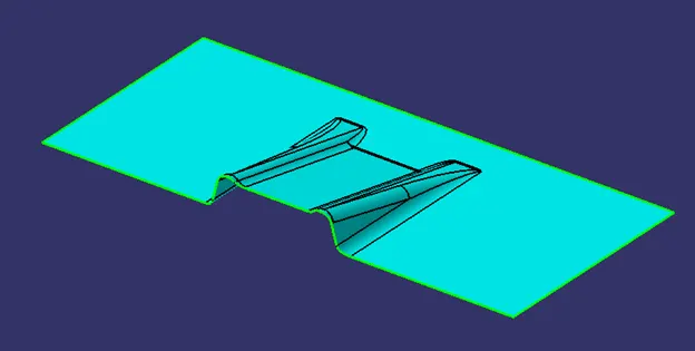
Fig.38 Edge fillet is applied with R.5.5 mm
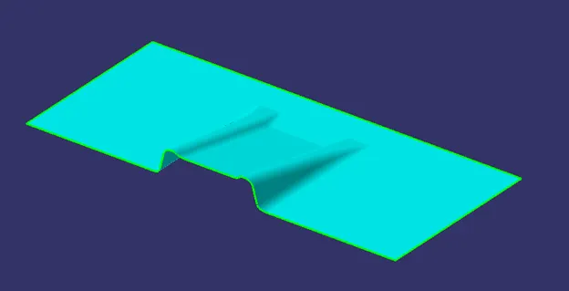
Fig.39 Final Class B surface
5. Class C surface
for creation of class C surface follow below steps-
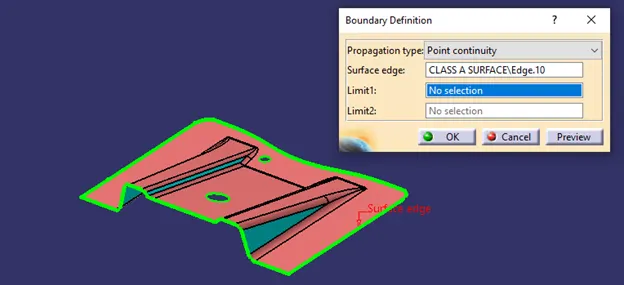
Fig. 40 create Edge boundary of class A surface
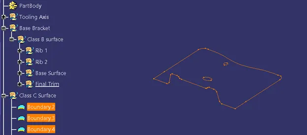
Fig. 41 Create boundaries of class A surface
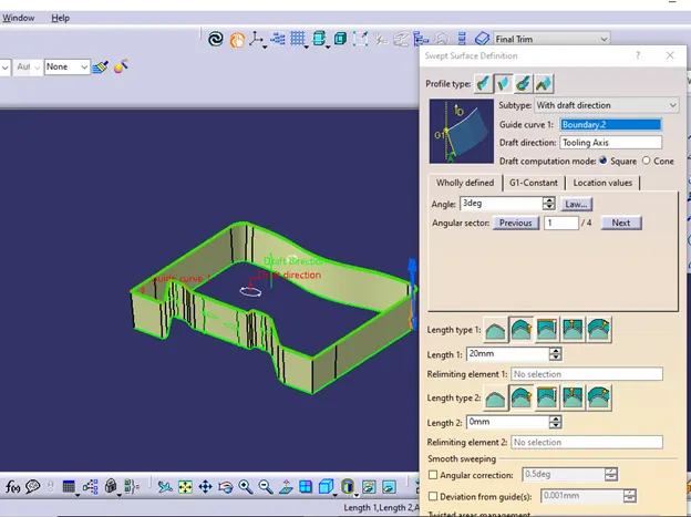
Fig.42 Sweep with draft of 3 degree in downward side
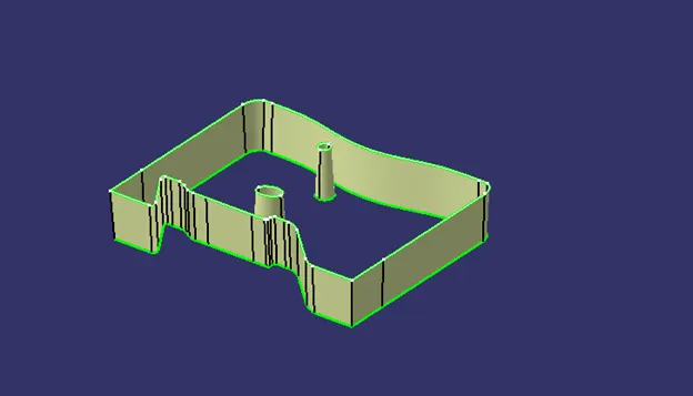
Fig.43 Swept of 2 holes with draft of 3 degree
- Join class A surface, edge boudary swept, 2 hole swept together.
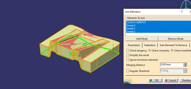
Fig. 44 Join Class A surface, Swept entities
- Trim class B surface with join feature, then we will get class C surface.
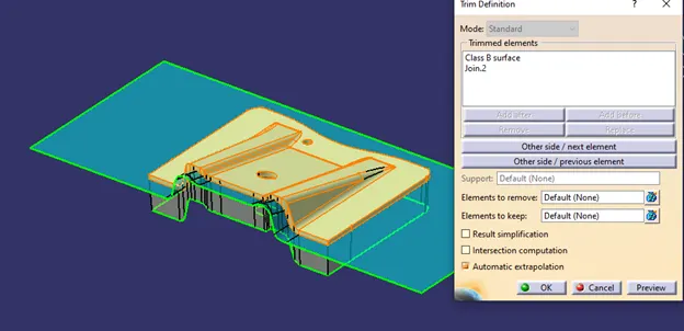
Fig.45 Trim class B surface and swept join
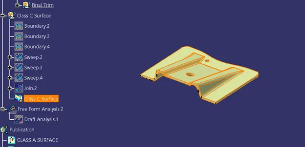
Fig.46 Final Class C surface
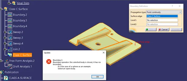
Fig.47 Closed boundary
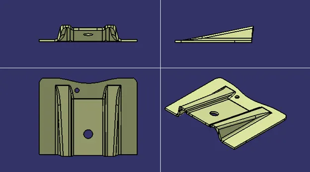
Fig. 48 Views of class C Surface
6. Publication
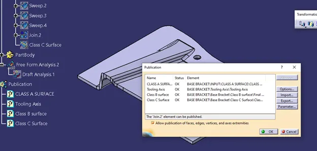
Publication feature is used to make easy access of published component (Surface or Sketch), here class A,B,C surface and tooling axis is published.
Path- Tools > Publication > Select entity (Surface/ Sketch/Body)
7. Closed Body-
Go to part design and convert Class C surface into solid body.
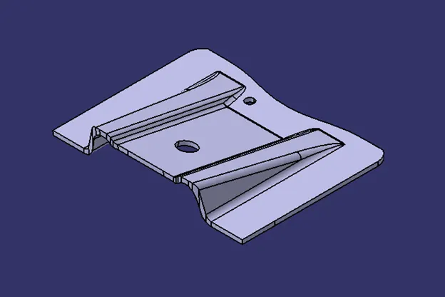
Fig.49 Closed Body
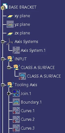
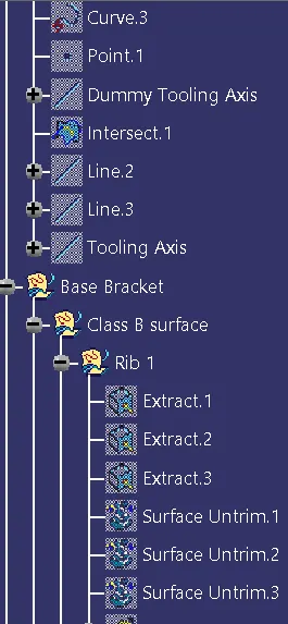
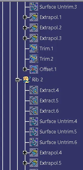
- Screen shots of tree structute, geometrical str. of tooling axis and draft analysis-
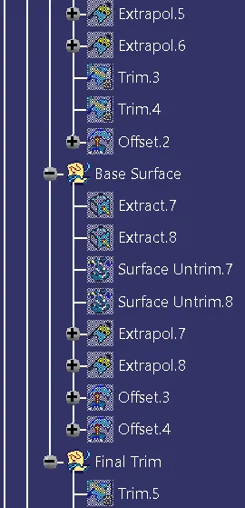
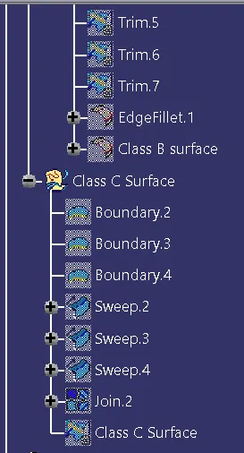
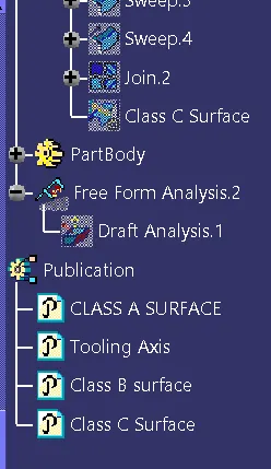
- Screenshots of the model with the proper color code of the draft angle in various orientations (Isometric, Front, Side, and Top View)
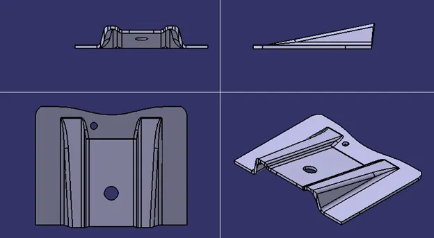
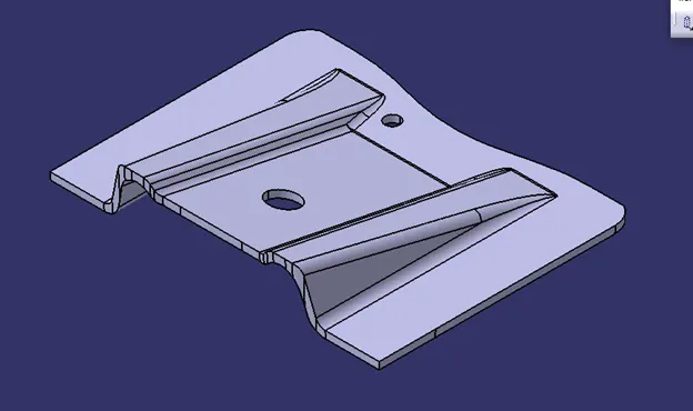
Fig.50 Isomteric view of base bracket body
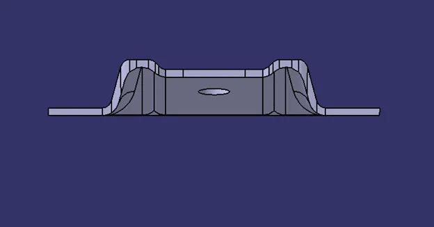
Fig.51 Front view of base bracket body
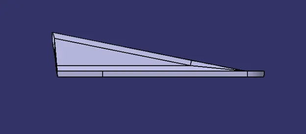
Fig.52 Side view of base bracket body
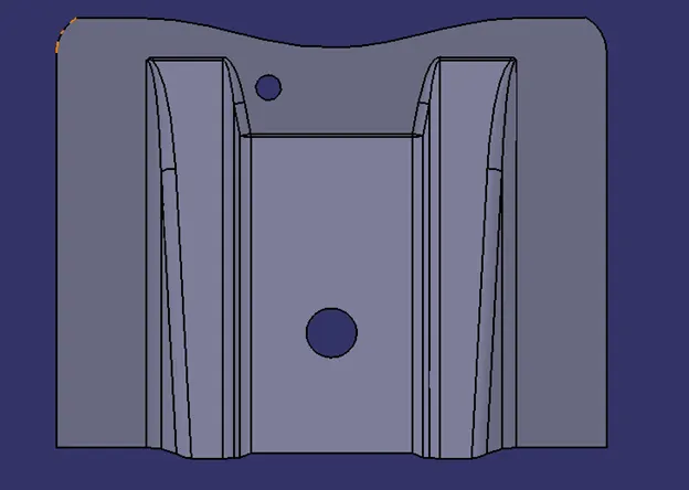
Fig.53 Top view of base bracket body