FINAL INDEPENDENT PROJECT
Solidworks- Final Independent Project
Title
Computer aided 3D modelling, assembly and rendering of Porsche 911 GT3 RS car.
Objectives-
The key objectives of this project are as follows:-
- To design and modelling of components of iconic car using sketch and modelling feature.
- To do assembly of car.
- To do render and make the realistic view of the car with different environments and view.
Software's Used-
3D modelling- DS SolidWorks (2020)
Rendering- Solidworks Visualize and Solidworks Photoview 360.
Abstract-
Any product developed in an industry comes out from the mind of a designer through the design, simulation, manufacturing and testing process. With the wide spread of popularity and versatility of CAD in various professional domains like product design, industrial design, etc. has become an essentiality for design engineer.
Being a design professional, I have always wanted to use Solidworks platform for completely designing and rendering my favorite car, the Porsche 911 GT3 RS. As an independent project to conclude my Solidworks training module, this design was the perfect fit. It presented me with an unique opportunity to implement the features I have learned and to add my own spin to it since the Project Brief offered me to prepare a design of my choosing with elements that I wanted to incorporate design approach. The following design methodology briefly explains the steps taken for completion of the design.
This report contains a detailed part modelling, assembly, final rendering of a custom designed Porsche 911 GT3RS Car in SOLIDWORKS as a CAD tool. Part modelling in general means to create a virtual prototype of a part. It can be used for various purposes. In part modelling, we first sketch the part/ component and create the 3D part using different features. Each part of assembly is modelled separately and they are assembled together with application of mates in assembly. Once the final assemble model of car is ready, we can do rendering, for the project real view / realistic rending in done in Solidworks Visualize. Suitable environment, lighting and background setting is done for the rendering.
Introduction-
The Porsche 911 GT3 is a high-performance homologation model of the Porsche 911 sports car. It is a line of high-performance models, which began with the 1973 911 Carrera RSThe GT3 has had a successful racing career in the one-make national and regional POrsche Carrera Cup and GT3 cup challenge series, as well as the international Porsche Super Cup supporting the FIA Formula 1World Championship. The car has been continuously enhanced through the years but the basic concept has remained unchanged. RS stands for Rennsport in German, meaning "racing sport".
Design Methodology-
- Blueprint Setup
- Car Exterior Body
- Frame
- Steering wheel
- Seat and Dashboard
- Engine
- Rim and Tire
- Rotor and Caliper
- Sub- Assembly
- Final Assembly
Details of 3D modelling in SOLIDWORKS-
- Solid Modelling-
The methods involves manipulating the bulk of an object via volume addition or subtraction commands. Three dimensional entities can be generated using 2D section or curves by drawing the directrix and generatrix. Even Boolean operations like union, intersection and subtraction can be applied on solid bodies to form the sophisticated shapes. Intricate detailing can be carried out much easily in modelling, since geometry can be made parametric which aids in model rebuilt when iterative revisions carried out.
- Surface Modelling-
Surface modelling is used to build out a represent of solid objects exterior and it’s a contours. In this project, most of the parts are designed as surface model at first. A surface is designed accurately and solid body is created out of the surface model one the knitting of surface is successfully done.
- Feature's Used-
- General- Sketch, 3D sketch (Line, arc, circle, spline, rectangle, Polygon, fillet, ellipse), offset, Trim and / Extend entity, Convert Entity, Mirror, Linear and / circular sketch pattern, smart dimension, dynamic mirror.
- Solid Model- Extruded Boss/Base, Extrude cut, Revolved Boss/Base, Revolved cut, Swept Boss/Base, Swept Cut, Lofted Boss/Base, Lofted cut, Fillet, Chamfer (Angle and / distance), Patterns (Linear pattern Circular pattern Curve Driven Pattern, Sketch Pattern), Shell, Dome (Face to dome / Elliptical Dome ), Split, Combine (Add/ Subtract/Common)
- Surface Model- Swept Surface, Lofted Surface, Boundary Surface, Filled Surface, Surface Trim, Extend Surface, Surface Knit, Offset Surface, Delete Face
- Appearance-An appearance is define the visual properties of model which include color and texture. We can apply appearance to the individually to the complete model / one or more face /edges .It does not affect on physical property which are defined by material.There are four ways to apply appearance-Surface, Feature, Body and Part Color.
Description of car parts and modelling in detailed-
- Blueprint Setup-
Blueprints are one of the most useful things for modelling in Solidworks. Iterative design approach has been employed in this project while creating components of the vehicle by checking for components overall aesthetic look and dimensions. Blueprints are basically orthogonal drawings in every direction (front, top, mid, bottom and back). They allow us to draw curves over a picture so that we can be precise and match the real shape.
Available blueprints images of the car are set as reference to help create some curves and estimate boundaries of the vehicle surface. The different view of the vehicle blueprints are inserted with adding dimension in planes. The main reference planes are renamed as front, top, back and mid-planes. These blueprints are helps to generate surfaces of vehicle body but also serves dimension for chassis, cabin.
Features used to create blueprint setup-
- Rename the Planes:-
Front Plane – Front Plane of blueprint setup
Top Plane- Top Plane of blueprint setup
Right Plane-Mid Plane of blueprint setup
- Create Reference Geometry/ New Plane
Back Plane w.r.t front plane of blueprint setup
- Addition of sketch pictures w.r.t each plane
- Renaming the Sketches w.r.t each planes
Eg. Blueprint _Front View
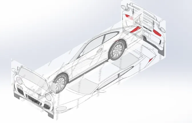
Fig.1 Blueprint Setup for car part modelling
2. Car Exterior Body-
Using the reference blueprints of car, the outer surface of the vehicle body is created. The exterior design of the vehicle develops the proportions, shape, and surface details of the vehicle. Exterior car body is first done by a series of manual sketches and blueprints.
The first principle to follow while designing is that of curvature. No matter how subtle the curve, every single surface on any car is curved. To keep design and manufacturing simple, cars tend to concentrate curvature in one direction. Most of the form is horizontal to the ground. As a result we will never find a completely flat surface on any car. The side view shows how the screen has no curvature from top to bottom. This is the most difficult part while designing. The shoulder line is most dominant feature of car, it can rise or fall, but is generally almost perfectly horizontal along the length of the car. 99% of production cars are manufactured from steel with plastic accessories, and glass windows.
Car panels are stamped by enormous presses from very thin, flexible sheet metal, and strength comes from curvature. Almost all these metal cars are welded together from these sections or panels of steel, creating joins we call panel gaps.
Most extensively used features to create surfaces are lofted surface, swept surface, fill surface, trim, extrude surface, knit surface.
Mid plane mirroring is used to make the whole the exterior body surfaces. Split line tools are used make text. Fuel tank cap, handles. Wheel cut outs at the fender areas and any excess of surface are trimmed off to match the shape of the original shapes. With the main surface body created and also light and left doors, mirror, panels, front - rear lights, handle, name plates, hood, exhaust are also created.
Extensively used features to create exterior car body-
- Use Blueprint file Sketch
- Sketch
- Fill Surface
- Lofted Surface
- Boundary Surface
- Swept Surface
- Knit Surface
- Trim Surface
- Move/Copy Body
- Revolve Boss/Base
- Extruded Cut
- Mirror
- Extrude Boss/Base
- Fillet
- Circular Pattern
- Split Line
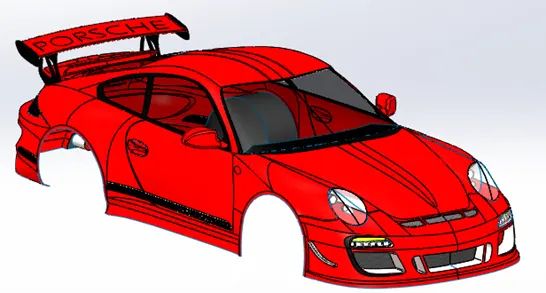
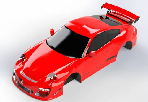
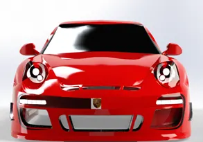
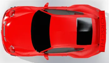
Fig. 2 Exterior Car body
2. Frame
The frame is composed of structural members serves as the under-body support. Frame is meant to sit inside the outer body.
Frame is created for this project is a simple ladder frame like design containing feature relevant to this aesthetic project. This contains engine mounting, control arms and differential casing. To design frame blueprints of car and exterior car body references are used. Hence blueprint setup model used for further modelling. The track width and wheel base of the car is adjusted by changing the width of control arm and length between the two arms.
Extensively used features to create frame are-
- Swept Boss/Base
- Extrude Boss/Base
- Extrude Cut
- Mirror
- Fillet
- Offset Surface
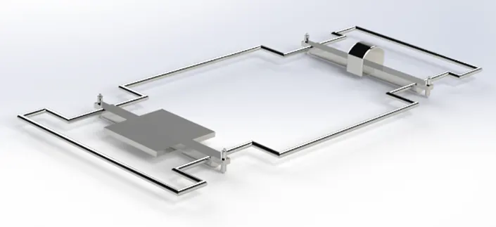
Fig. 3 Frame of car
4. Seats and Dashboard
The seats and dashboard can be customized as per designer choice and as per choice interiors are too added. In order to get the region where dashboard and seats has to be designed, the primary reference taken are engine mounting surface and blueprints. Engine mounting surface should be coincident with cabin floor and also planes of blueprint setup are coincident with modelling planes. The length and width of seats and dashboard are adjusted w.r.t mid-planes / front and side blueprint.
In the design of dashboard panel accessories details are added like steering column, drawers, handles, lever gauge, Gauges, indicators, indicator needle, clutch, brakes, etc. The interior / cabin Space and dashboard panel design completed, the space left used for seat design. Seat length, width, hand rest, hand brake, steering column and head rest are designed roughly. Mirror feature used to generate reaming seat and head rest about mid plane.
For the design dashboard height value is challenging because interior side blueprint are not available. All dimension are roughly matched and adjusted to achieve satisfactory result.
Extensively used features to create frame are-
- Extrude Boss/Base
- Revolve Boss/Base
- Extrude Cut
- Mirror
- Chamfer
- fillet
- Swept Boss/ Base
- Surface Fill
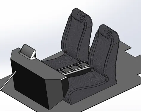
Fig. 4 Seat and Dashboard panel in Iso-metric view
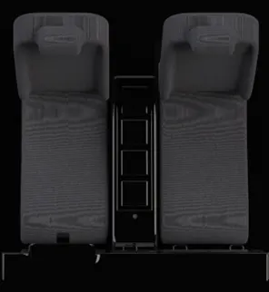
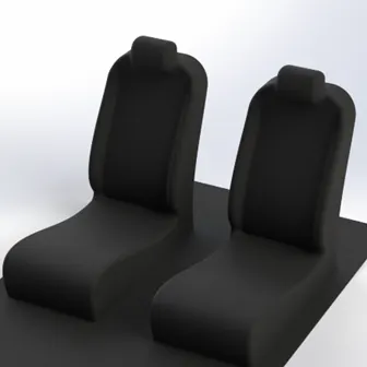
Fig. 5 Seat modelling
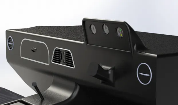
Fig. 6 Dash Board Panel
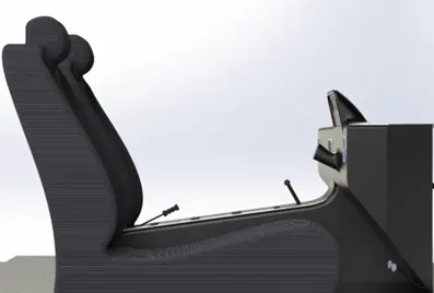
Fig. 7 Seat and Dash board side view (Hand brake, Gear Lever, Clutch, and Brake)
5. Steering Wheel
For this project simple customized circular wheel is modeled because no sketch is available for reference. A wheel is with dished center linking flat plate arm is designed. For the design reference steering column surface is used from seat and dashboard model. Proper appearance is applied to the wheel and text is engraved by using split line command.
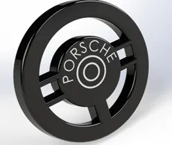
Fig. 8. Steering Wheel
6. Engine
As no internal useable blueprint of car are available, so the dimension of model are obtained from engine mounting and exterior car body rear surfaces. The engine length and height are adjusted from exterior car body and seat during final assembly. Challenging part for engine modelling are to adjust length of an engine and length of exhaust manifold because they became visible from car exterior body when all part are assembled in final assembly.
The engine modelled for this project is a cosmetic/ customize version. i.e the engine model appears only externally but not internal elements of an engine. The model only involved external parts like cylinder block or engine block, head gasket, cylinder head, intake manifold, exhaust manifold, crankshaft- camshaft –pulleys-motor with drive belt, oil pan, etc. the model is with stamped – engraving and appearance is applied just for aesthetic look.
Extensively used features to create an engine are-
- Extrude Boss/Base
- Revolve Boss/Base
- Extrude Cut
- Mirror
- fillet
- Revolve Cut
- Swept Boss/ Base
- Move/ copy body
- Circular Pattern
- Linear pattern
- Swept Surface
- Surface Extrude
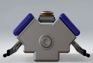
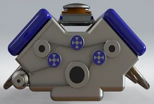
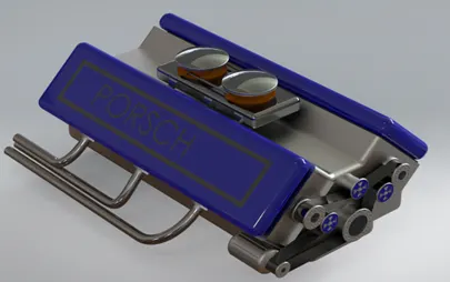
Fig. 9 Engine
7. Rim and Tire
The rim is the outer edge of a wheel, holding the tire. It makes up the outer circular design of the wheel on which the inside edge of the tire is mounted on car/ vehicle.
Tire is a circular shaped components around rim, to transfer the load from axle to ground through wheel. Tires are pneumatically inflated provides a flexible cushion, that absorb shocks as the tire rolls over .rough features on the surface. The materials of modern pneumatic tires are synthetic rubber, natural rubber, fabric and wire, along with carbon black and other chemical compounds. They consist of a tread and a body. The tread provides traction while the body provides containment for a quantity of compressed air.
For this project front and rear wheels are kept as same and also C-channel is mount on hub. The rim and tire is made by using reference of blueprint and dimensions from exterior car body.
Extensively used features to create rim and tire-
- Use Blueprint file
- Sketch
- Revolve Boss/Base
- Extrude Boss/Base
- Extruded Cut
- Fillet
- Mirror
- Circular Pattern
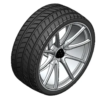
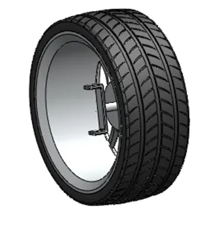
Fig.10 Rim and Tire
8. Rotor-
The rotors are the circular discs that are connected to each wheel (two in the front and two in the back). Rotors are designed to turn motion (kinetic energy) into thermal energy (heat). The brake rotor is a disc connected to rim’s hub.
The rotor is design by taking reference dimension from rim and tire.
Extensively used features to create rotor are -
- Extrude Boss/Base
- Extrude cut
- Mirror
- Circular pattern
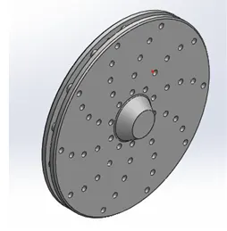
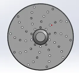
Fig.11 Rotor
11. Caliper
A brake caliper forms the heart of a disc brake system. It enables the braking action to happen, something that enhances safety and drivability. Caliper function is to low the car's wheels by creating friction with the brake rotors. The brake caliper fits like a clamp on a wheel's rotor to stop the wheel when we press the brakes. Inside each caliper is a pair of metal plates known as brake pads.
The design of caliper is same as rotor, i.e dimension are taken from rotor and rim- tire model.
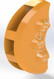
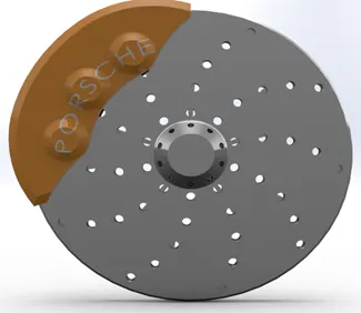
Fig.12 Caliper and Caliper- Rotor Assembly
Assembly of Porsche 911 GT3 RS
1. Creating the Subassembly -1
Inserted part modelled file-
- Rim and Tire,
- Rotor
- Caliper
This sub- assembly completes the complete wheel modelling having a well mating of rim with tire, rotor and caliper , so that we can easily mate the wheel with frame in final assembly. Mates creates geometric relations with the components which are inserted into the assembly.
Rim and rotor modelled part is used as fixed part in the assembly. Next inserted part model are rotor and caliper respectively.
Extensively used mates for sub-assembly are standard type of mates i.e coincident, concentric and parallel. For this project no turning movement of wheel is defined but we can defined in the sub-assembly. Rotor part is coincident and concentric with rim hub, whereas caliper is mates with rotor.
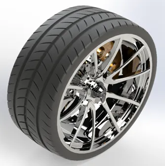
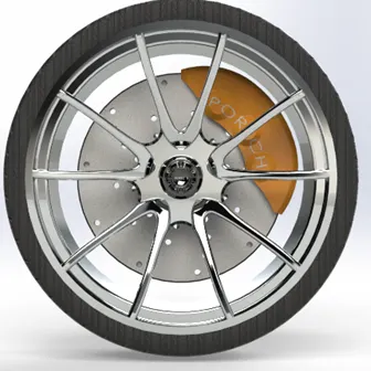
Fig.13 Isometric, Front of wheel Assembly
2. Final Porsche car Assembly
Inserted part modelled file-
- Frame
- Engine
- Seat and Dashboard
- Steering Wheel
- Wheel Sub-Assembly
- Exterior car body
Final main assembly is made of above part inserted part modelled. For the main assembly frame modelling is the inserted as fixed part in the assembly. Next inserted parts are seat and dashboard, engine, steering wheel, engine, exterior car body and wheels at rear and front side respectively. Here wheels are kept same for the rear as well as front side and they are separately mates to the frame with the C-channel and king pin.
Extensively used mates for main assembly are standard type of mates’ i.e coincident, concentric and or concentric lock, distance and parallel. Seat and dashboard model is mates reference frame surface and planes of frame. Steering wheel is mates with steering column surface and planes of frame. Engine is mates with frame plane and distance is added w.r.t differential casing of frame. Car body is mates with plane of frame.
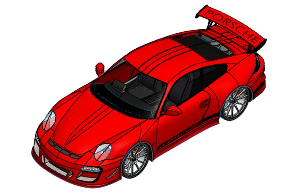
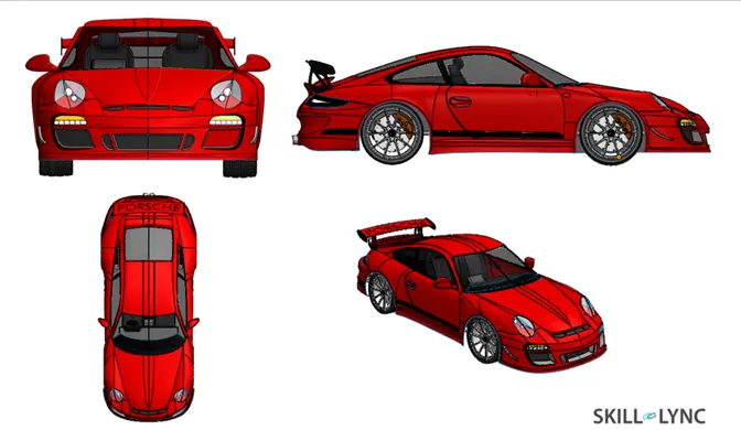
Fig.14 Isometric, Front, Top, Left Side and Camera View of car Assembly
Decals used for Porsche 911 GT3 RS car-
- Decals is used for this project is Porsche car logo and it is applied to the front surface of exterior car body.
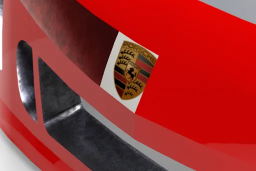
Fig. 15 Decals on car
Rendering of Porsche 911 GT3 RS Car-
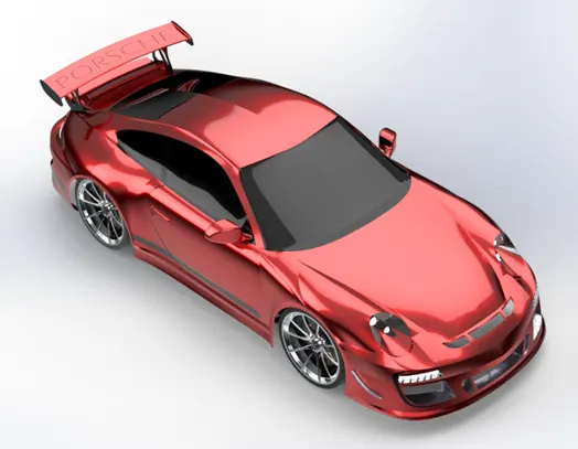
Once the final assemble model of car is ready, we can do rendering, for the project real view / realistic rending in done in Solidworks Visualize. Suitable environment, lighting and background setting is done for the rendering.
The following are the final rending images for this project -
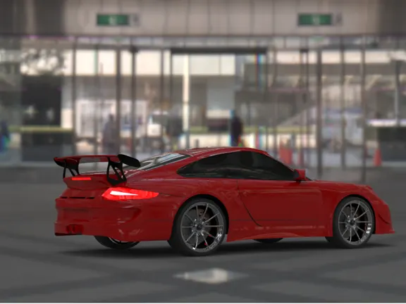
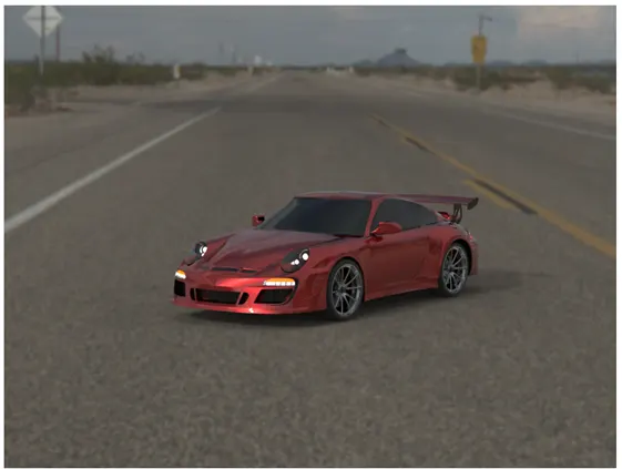
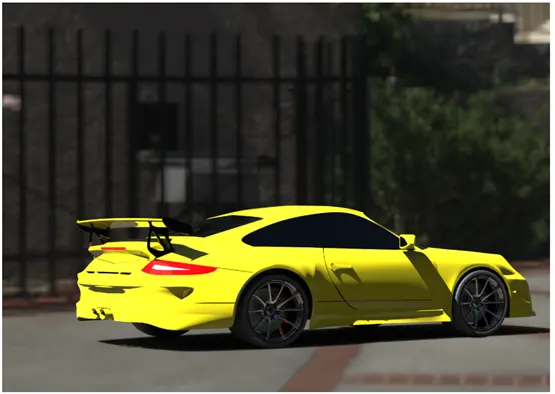
Fig. 16 Realistic rendered images with environment of car Assembly
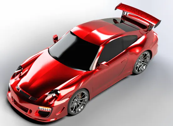
Fig. 17 Rendered image in Isometric View
 '
'
Fig. 18 Rendered image in Camera View
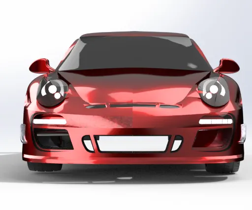
Fig. 19 Rendered image in front View
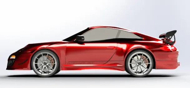
Fig. 20 Rendered image in Right Side View
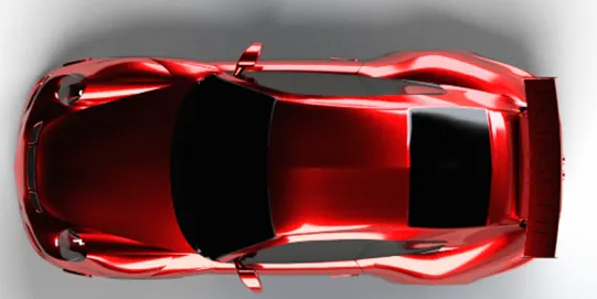
Fig. 21 Rendered image in Top View
Future Scope-
- In detailed designing of interior and exterior car modelling with addition of time.
- Feasible designing of car parts can be made to make the car more realistic and technically complete. E.g a shock absorber, axle, gear assembly, movements of hood, doors, etc.
Conclusion-
- The parts of iconic are sketched and modelled in the SOLDWORKS.
- The modelled parts are assembled with possible mates in to the main assembly of car.
- The realistic images was rendered with use of both ways “Photoview 360 and Solidworks Visualize.
- This project has helped to enhance the skills in surface modelling and product design.
- It has given me insight into automobile vehicle design and opportunity to build one.
References-
- Blueprints of Porsche 911 GT3 RS car from Google
- Porsche Logo
- Engine Design- https://www.youtube.com/watch?v=Hna4V7-FJ08
- Seat Design- https://www.youtube.com/watch?v=TOqR4sXUcWY