Week 8 - Challenge 3 - Coin Holder Design
Aim -
Create the Coin Holder Plastic component through the given Class-A surface. To begin with, the tooling axis for the given Class-A Surface should be created meeting the requirements of the draft angle and at the end perform the Draft analysis on the model.
INTRODUCTION:
CLASS-A SURFACE: a surface made by the designer which is given as an input to the plastic modeler to work on. It is aesthetic surface and the outer most surface.
CLASS-B SURFACE: a surface below a certain thickness from the class-A surface is class-B surface. This is the surface that contains engineering aspects of a model.
CLASS-C SURFACE: a surface that joins class-A and class-B surfaces is class-C surface.
objectives :
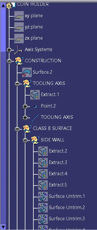
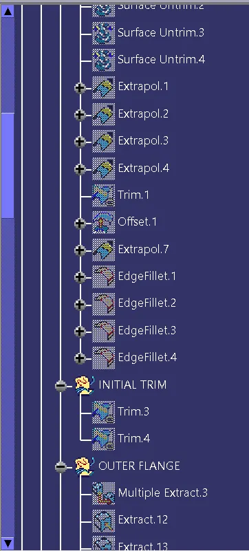
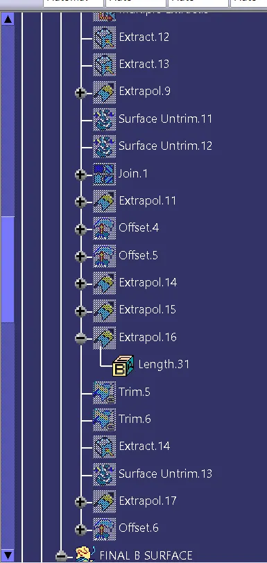
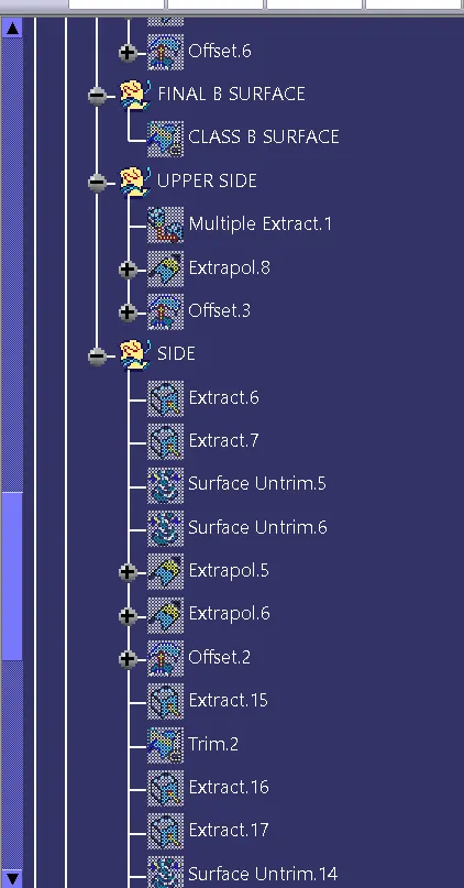
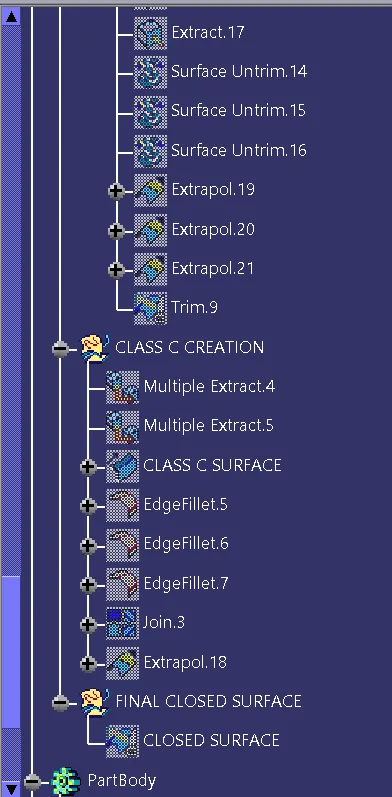
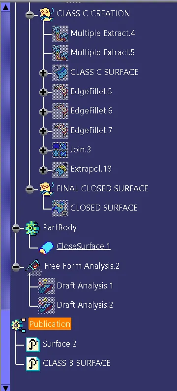
- To ensure proper tree structure is followed
- To keep the design as per requirement
- All the sketches should be iso constrained
- To publish the Class A,B and C Surface.
Tooling Axis
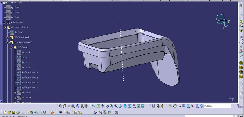
The tooling axis is defined as the direction in which the mold or core and cavity opens is the tooling axis.
Tooling Axis is created by three methods
- Choosing any one of the standard axis
- Normal to anyone of the surface
- Bisecting line
First create the point for the reference of tooling axis,now using point as a reference we create a line normal to the surface.
Draft Analysis for Class A Surface:
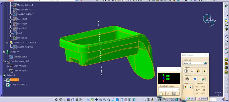
- The Drafting analysis was performed on the class-A surface by using the Feature Draft Analysis command.
- Using this command, the compass was set on the main tooling axis and the Draft angle was changed to 3 degrees.
CLASS B SURFACE CREATION:
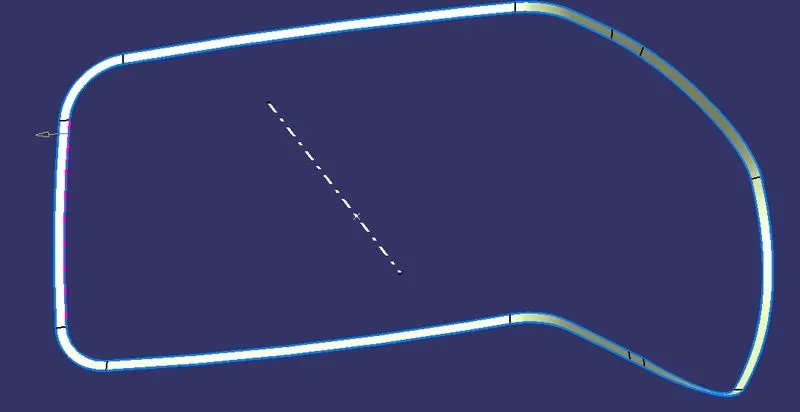
- From the Class A surface , Extracted a set of Surface for to create the Class B surface by Using Extract Command From Below Image.
- We can use extract command for all surface we needed for to create Class B Surface and then Use the Untrim command to restore the surface up to the limit.
- The Surface at which features like Side walls, base, top walls and Outer walls etc. are made to support external mountings is called Class B Surface.
- Class B Surface is made by simply extracting A Surface, offset it to desired thickness and trimming them together.
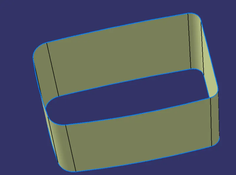
- We start creating the class B surface for that we offset all the flat surface to 2.5mm and then we use the untrim tool to untrim the surface and then use the extrapolate tool to extend the surfaces. We do this the for all the separate sections we created and then we trim all the sections together.
- Then we use edge fillet to fillet the corners wherever it needs.
CLASS C -SURFACE:
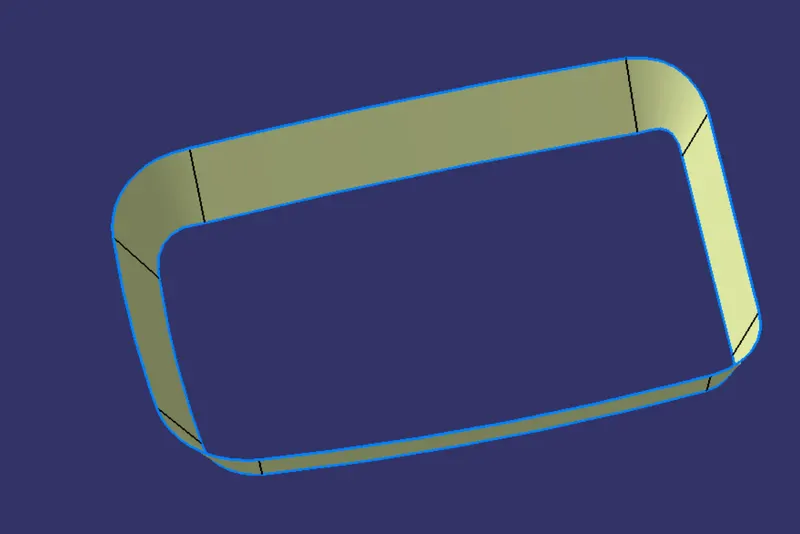
- Class C surface is a connecting surface between Class A and Class B surface.
- Draft angle and Tooling direction are considered while making Class C Surface.
- For this model the class C would be parallel to the horizontal plane because of the design of class A and class B.
- We first extract the edges from the Class A surface with the help of which we create the path for sweep for class C and the we even extract the adjacent surfaces to use it as a reference plane.
- So we select the sweep tool and in that we select with reference surface option and then we change the angle to 90° for it to be horizontal.
Tree Structure:
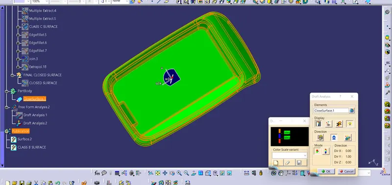
Draft Analysis for Solid component:
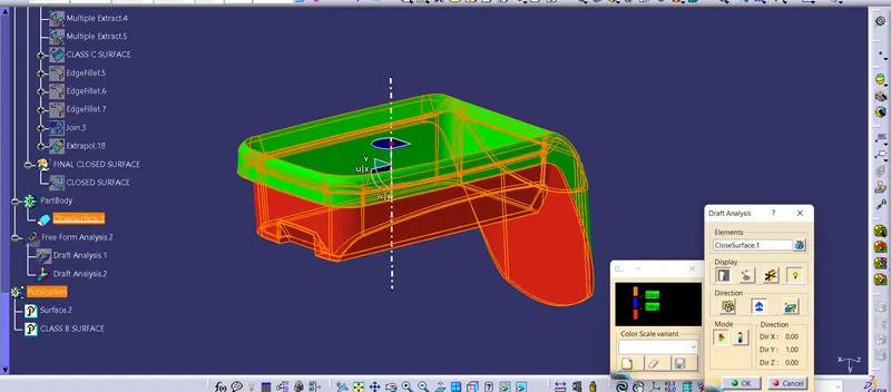
SOLID BODY:
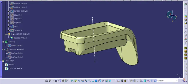
ISOMETRIC VIEW:
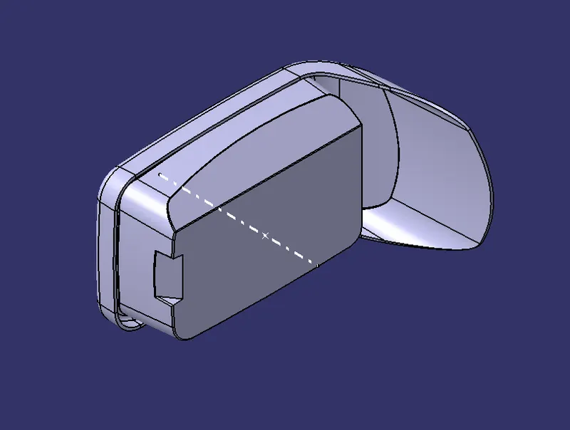
FRONT VIEW:
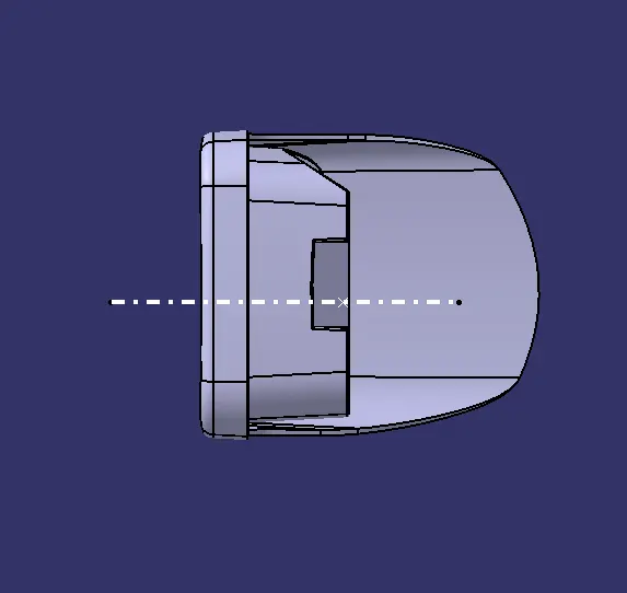
TOP VIEW:
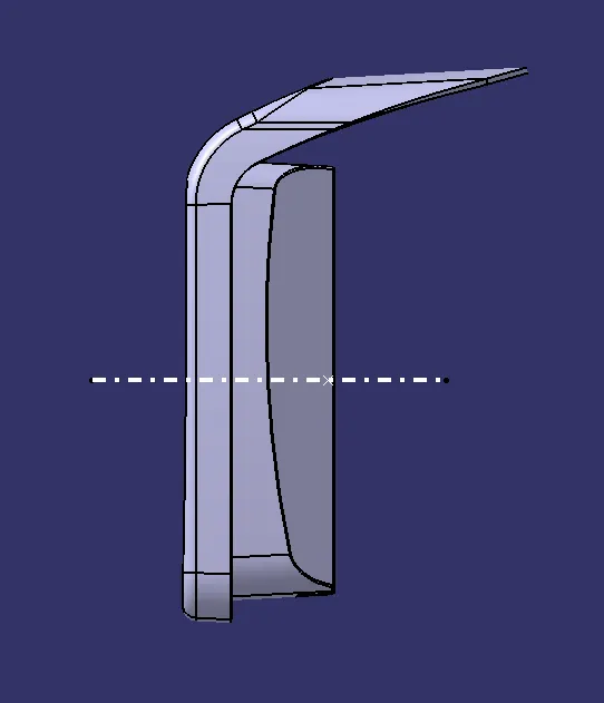
RIGHT SIDE VIEW:
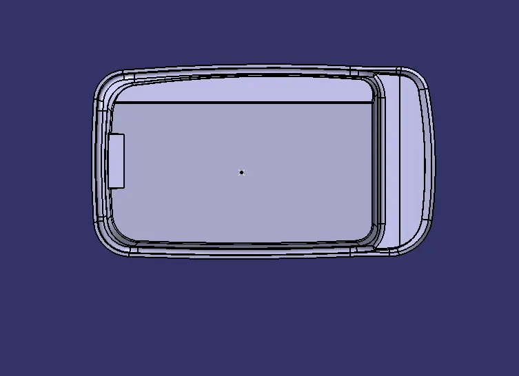
CONCLUSION:
- The main tooling axis and the side core tooling axis have been created successfully using the feature draft analysis tool.
- Final closed surface has been created by using the trim and join faeture.
- The part body has been created by using closed surface tool.
- Draft analysis has been successfully done on the part body.
- Thus the above challenge has been finished with the proper input and all the required documents are attached.