Week 7 - Minor Project
In this project, a simulation of a NACA0012 airfoil will be performed in ANSYS Fluent for various angles of attack and flow speed.
The angles of attack are: 5, 10 and 15 degrees
Flow conditions are: subsonic (0.15 times the mach number) and supersonic (1.2 times the mach number)
The effect of these on the lift and drag coefficents will be evaluvated.
Geometry
The intial .dat file was imported from http://www.basiliscus.com/ProaSections/AppendixD/TableD1.txt
The symmetric airfoil has a chord length of 1m, with a maxium camber of 0.1m at a distance of 0.2m from the trailing edge.
Since SpaceClaim requires the input .dat file to be in a specific format, the contents were modified and the input geometry is as follows:
Polyline = true
1	1		0.00126
1	0.992704	0.002274
1	0.979641	0.004079
1	0.964244	0.006169
1	0.947231	0.008434
1	0.929323	0.010765
1	0.910956	0.013101
1	0.892372	0.01542
1	0.873723	0.0177
1	0.855041	0.019931
1	0.836311	0.022119
1	0.817558	0.024266
1	0.798819	0.026366
1	0.780088	0.028414
1	0.761336	0.030413
1	0.74256		0.03237
1	0.72378		0.034284
1	0.705012	0.036149
1	0.686255	0.037964
1	0.667502	0.039728
1	0.648751	0.04144
1	0.630004	0.043098
1	0.611266	0.044701
1	0.592538	0.046245
1	0.573821	0.047728
1	0.555117	0.049149
1	0.53643		0.050503
1	0.517763	0.051786
1	0.499117	0.052996
1	0.480488	0.054127
1	0.461875	0.055178
1	0.443287	0.056144
1	0.42474		0.057019
1	0.406241	0.057796
1	0.387789	0.058466
1	0.369372	0.059023
1	0.350989	0.059462
1	0.332648	0.059779
1	0.314366	0.059965
1	0.296159	0.060009
1	0.278033	0.059903
1	0.259997	0.059634
1	0.24206		0.059191
1	0.224236	0.058562
1	0.206544	0.057733
1	0.189011	0.056692
1	0.171676	0.055421
1	0.154596	0.053909
1	0.137852	0.052138
1	0.121548	0.050098
1	0.105827	0.047785
1	0.090903	0.04522
1	0.077039	0.042449
1	0.064541	0.039548
1	0.053594	0.036612
1	0.044211	0.033717
1	0.036254	0.030913
1	0.029567	0.028218
1	0.023982	0.025653
1	0.01931		0.023217
1	0.015371	0.020871
1	0.012012	0.018579
1	0.009117	0.016316
1	0.006653	0.014058
1	0.004621	0.011797
1	0.003007	0.009544
1	0.001777	0.007318
1	0.000894	0.005155
1	0.000322	0.003059
1	0.000036	0.001014
1	0.000036	-0.001014
1	0.000322	-0.003059
1	0.000894	-0.005155
1	0.001777	-0.007318
1	0.003007	-0.009544
1	0.004621	-0.011797
1	0.006653	-0.014058
1	0.009117	-0.016316
1	0.012012	-0.018579
1	0.015371	-0.020871
1	0.01931		-0.023217
1	0.023982	-0.025653
1	0.029567	-0.028218
1	0.036254	-0.030913
1	0.044211	-0.033717
1	0.053594	-0.036612
1	0.064541	-0.039548
1	0.077039	-0.042449
1	0.090903	-0.04522
1	0.105827	-0.047784
1	0.121548	-0.050098
1	0.137852	-0.052138
1	0.154596	-0.053909
1	0.171676	-0.055421
1	0.189011	-0.056692
1	0.206544	-0.057733
1	0.224236	-0.058562
1	0.24206		-0.059191
1	0.259997	-0.059634
1	0.278033	-0.059903
1	0.296159	-0.060009
1	0.314366	-0.059965
1	0.332648	-0.059779
1	0.350989	-0.059462
1	0.369372	-0.059023
1	0.387789	-0.058466
1	0.406241	-0.057796
1	0.42474		-0.057019
1	0.443287	-0.056144
1	0.461875	-0.055178
1	0.480488	-0.054127
1	0.499117	-0.052996
1	0.517763	-0.051786
1	0.53643		-0.050503
1	0.555117	-0.049149
1	0.573821	-0.047728
1	0.592538	-0.046245
1	0.611266	-0.044701
1	0.630004	-0.043098
1	0.648751	-0.04144
1	0.667502	-0.039728
1	0.686255	-0.037964
1	0.705012	-0.036149
1	0.72378		-0.034284
1	0.74256		-0.03237
1	0.761336	-0.030413
1	0.780088	-0.028414
1	0.798819	-0.026366
1	0.817558	-0.024266
1	0.836311	-0.022119
1	0.855041	-0.019931
1	0.873723	-0.0177
1	0.892372	-0.01542
1	0.910956	-0.013101
1	0.929323	-0.010765
1	0.947231	-0.008434
1	0.964244	-0.006169
1	0.979641	-0.004079
1	0.992704	-0.002274
1	1		-0.00126
1	1		0.00126
Importing this into SpaceClaim will create an enclosed curve in the shape of the NACA0012 airfoil.
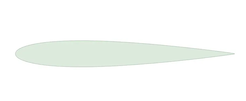
This is the airfoil seen in SpaceClaim:
A wind tunnel or enclosure was drawn around the airfoil, to the following dimensions.
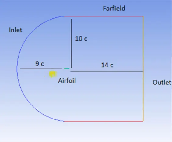
This is the airfoil with the wind tunnel seen in SpaceClaim:
Calculation of Wall Spacing/Inflation Parameters
Subsonic flow
Inlet velocity: 52 `m//s`
Density of Air: 2.131 `kg//m^3`
Required y+ : 1
Plugging in these values to https://www.cadence.com/en_US/home/tools/system-analysis/computational-fluid-dynamics/y-plus.html
We get,
Wall Spacing: 4.32 `mum`
Reynold's Number: 6.19 million
For 20 layers and a growth rate of 1.2 per layer the maximum thickness of the inflation layer is 0.8078mm.
Supersonic Flow
Inlet velocity: 400`m//s`
Density of Air: 2.131 `kg//m^3`
Required y+ : 30 (note: higher y+ was used due to extremely high reynold's number)
Plugging in these values to https://www.cadence.com/en_US/home/tools/system-analysis/computational-fluid-dynamics/y-plus.html
We get,
Wall Spacing: 9.585 `mum`
Reynold's Number: 48.58 million
For 20 layers and a growth rate of 1.2 per layer the maximum thickness of the inflation layer is 1.7895mm.
Meshing
The default quadrilateral mesh with a sizing of 0.25m is used. Two additional controls are introduced, they are as follows:
1. Controls -> Inflation
This control is to accurately capture the boundary layer near the surface of the airfoil.
The maximum thickness for
Subsonic flow: 0.8078mm
Supersonic flow: 1.7895mm
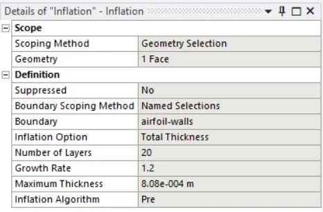
2. Controls -> Sizing -> Edge Selection
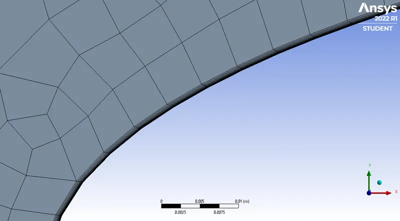
This control is to ensure the curvature of the airfoil is captured accurately in the mesh region near the airfoil.
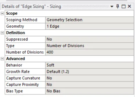
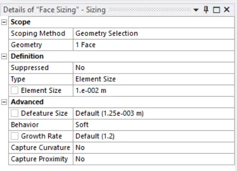
3. Controls -> Face Meshing
This control is to specify a different element size for the refinement region. The element size is 0.01m.
The mesh has 50844 nodes and 50535 elements.
This is the final mesh,
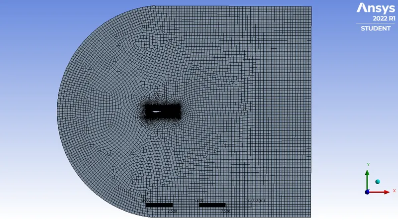
Zooming in to the refinement region,
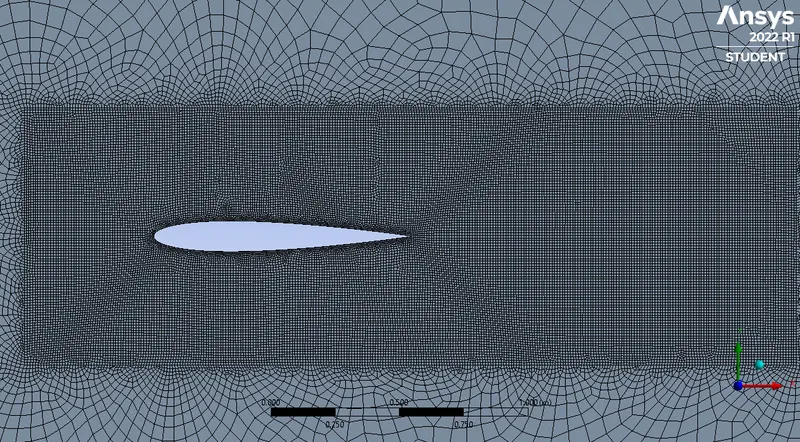
Airfoil,
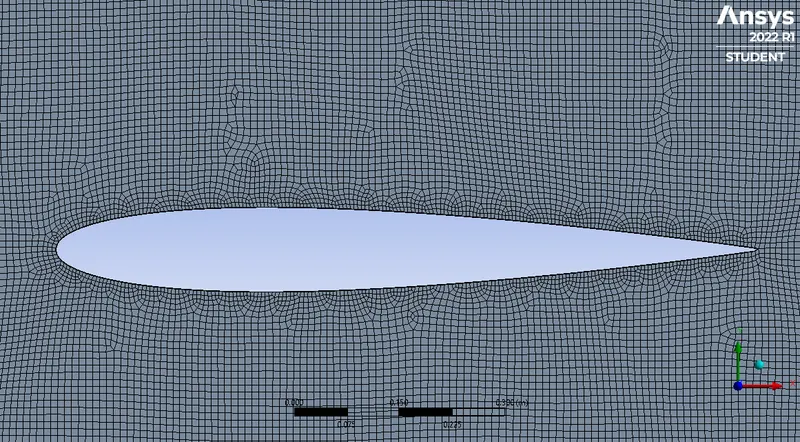
Inflation layers,
Mesh Metrics
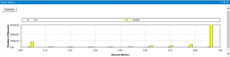
Nearly all elements have a quality >0.9, hence it can be said the mesh quality is satisfactory.
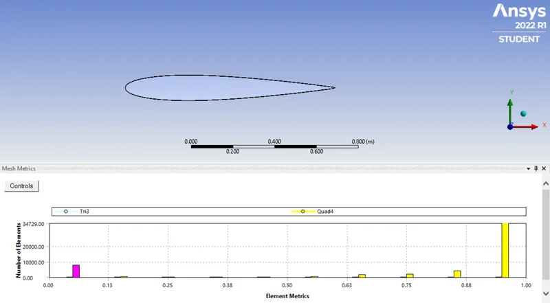
Some elements have a very low quality but those elements are part of the inflation layer hence they can be ignored.
Simulation Setup
The solver was a pressure based, steady state and planar (2D) simulation.
Reference Values
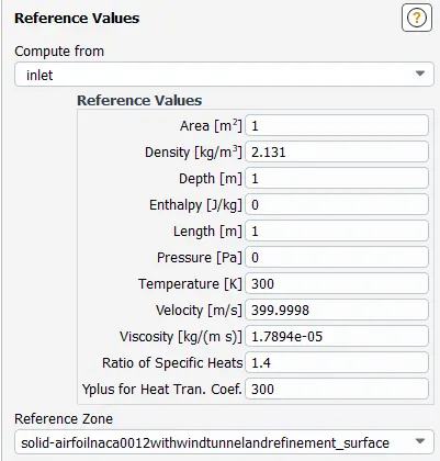
Note: The velocity was changed depending on the flow - subsonic or supersonic.
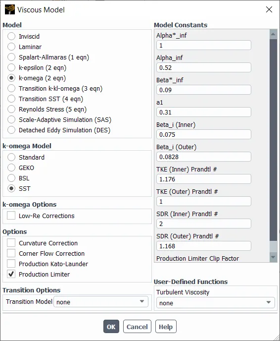
Viscous Model
The turbulence model used was k omega - SST due to its excellence in solving external flow simulations.
Boundary Conditions
inlet: velocity-inlet - Components
outlet: pressure-outlet - 0Pa
others: symmetry
airfoil: walls
Reports
Two reports were generated, Lift Coefficent and Drag Coefficent. The force vectors for each depended on the angle of attack of the airfoil.
The simulation was performed for 200 iterations or until residuals dropped below 1e4, the results are below:
Subsonic Flow
Case 1
Angle of Attack: 5 degrees
Velocity component at inlet (X): 51.802 m/s
Velocity component at inlet (Y): 4.53 m/s
Drag Coefficient Force Vector (X,Y): 0.9961, 0.08715
Lift Coefficient Force Vector (X,Y): 0.08715, 0.9961
Results
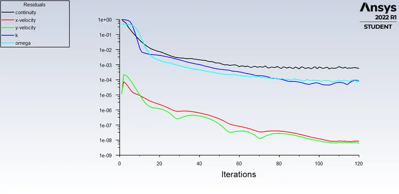
This simulation ran for 120 iterations. These plots were taken in Fluent.
Residuals
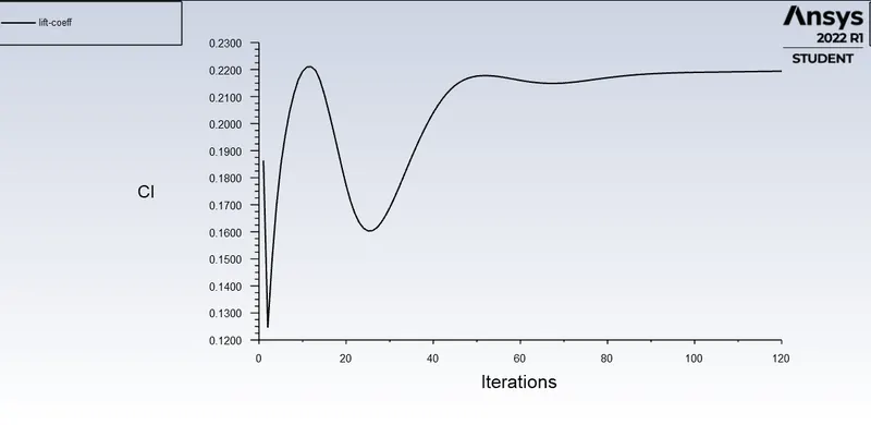
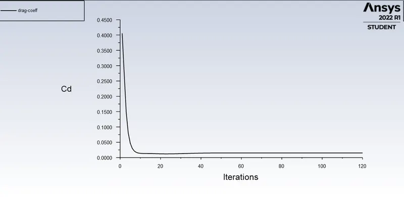
The simulation can be said as converged due to low and stable residuals, and due to steady lift and drag coefficients.
Coefficent of Lift
Value: 0.21940
Coefficient of Drag
Value: 0.015234
Case 2
Angle of Attack: 10 degrees
Velocity component at inlet (X): 51.21m/s
Velocity component at inlet (Y): 9.029m/s
Drag Coefficient Force Vector (X,Y): 0.9961, 0.08715
Lift Coefficient Force Vector (X,Y): 0.08715, 0.9961
Results
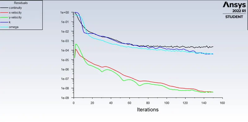
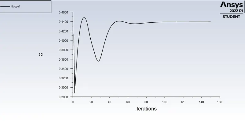
This simulation ran for 150 iterations. These plots were taken in Fluent.
Residuals
The simulation can be said as converged due to low and stable residuals, and due to steady lift and drag coefficients.
Coefficent of Lift
Value: 0.43924754
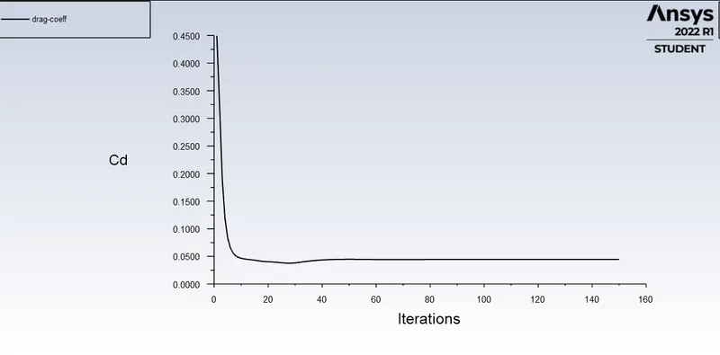
Coefficient of Drag
Value: 0.044625648
Case 3
Angle of Attack: 15 degrees
Velocity component at inlet (X): 50.22m/s
Velocity component at inlet (Y): 13.45m/s
Drag Coefficient Force Vector (X,Y): 0.9659, 0.2588
Lift Coefficient Force Vector (X,Y): 0.588, 0.9659
Results
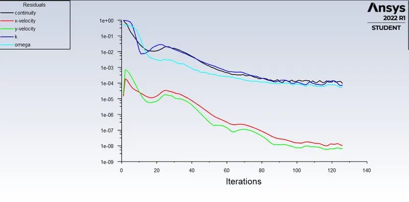
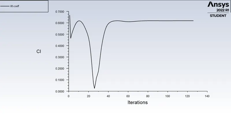
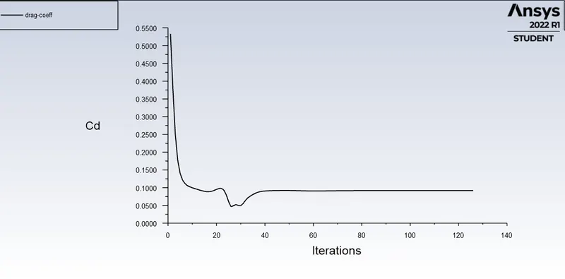
This simulation ran for 126 iterations. These plots were taken in Fluent.
Residuals
The simulation can be said as converged due to residuals dropping below 1e-4.
Coefficent of Lift
Value: 0.61806
Coefficient of Drag
Value: 0.091745
Supersonic Flow
Case 1
Angle of Attack: 5 degrees
Velocity component at inlet (X): 398.477 m/s
Velocity component at inlet (Y): 34.862 m/s
Drag Coefficient Force Vector (X,Y): 0.9961, 0.08715
Lift Coefficient Force Vector (X,Y): 0.08715, 0.9961
Results
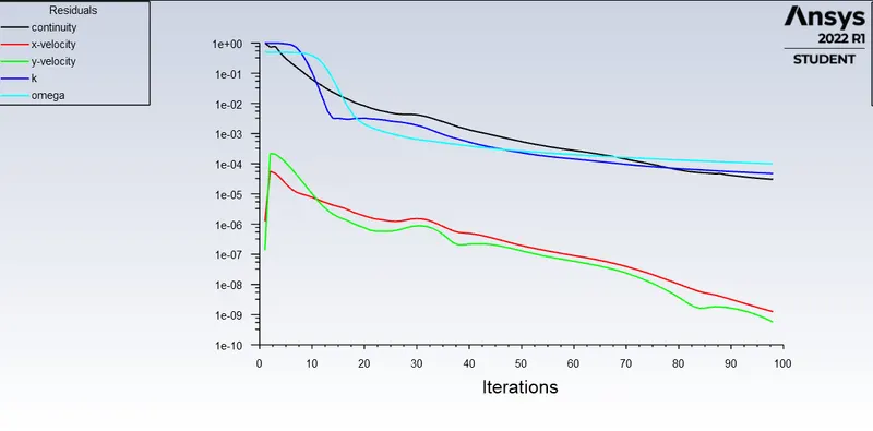
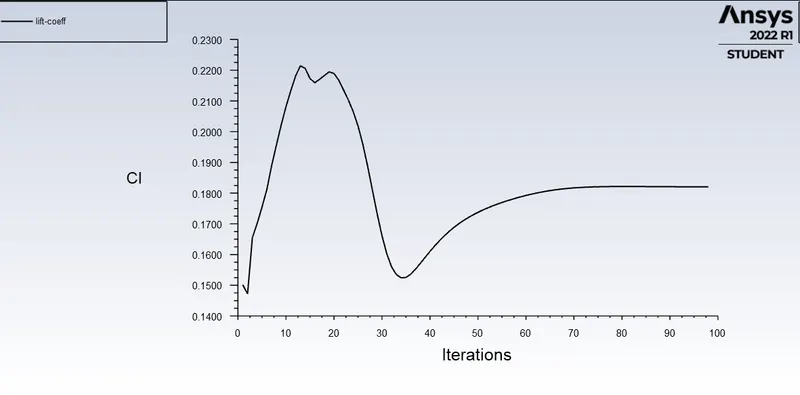
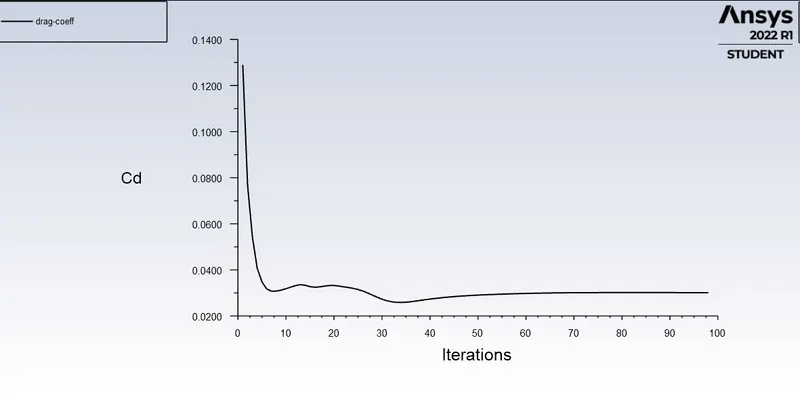
This simulation ran for 98 iterations. These plots were taken in Fluent.
Residuals
The simulation can be said as converged due to residuals dropping below 1e-4.
Coefficent of Lift
Value: 0.18205569
Coefficient of Drag
Value: 0.030150293
Case 2
Angle of Attack: 10 degrees
Velocity component at inlet (X): 393.923 m/s
Velocity component at inlet (Y): 69.459 m/s
Drag Coefficient Force Vector (X,Y): 0.9961, 0.08715
Lift Coefficient Force Vector (X,Y): 0.08715, 0.9961
Results
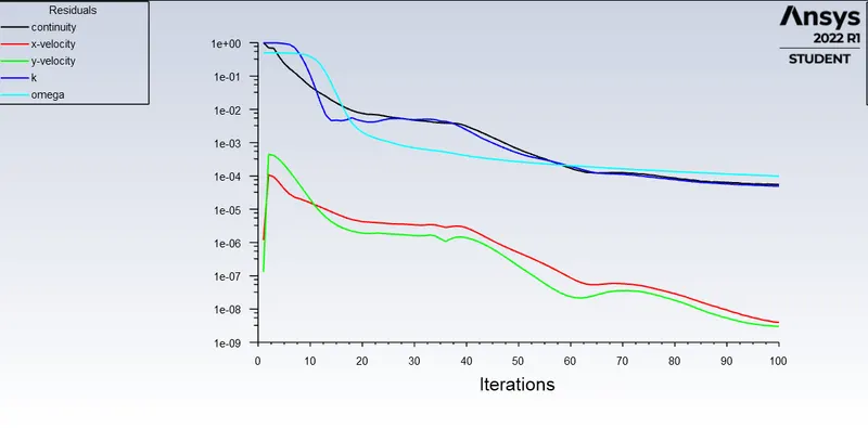
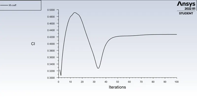
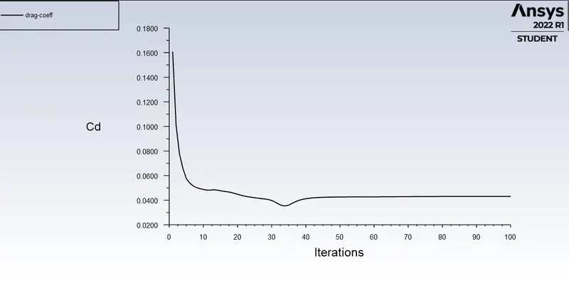
This simulation ran for 100 iterations. These plots were taken in Fluent.
Residuals
The simulation can be said as converged due to residuals dropping below 1e-4.
Coefficent of Lift
Value: 0.42726323
Coefficient of Drag
Value: 0.043082967
Case 3
Angle of Attack: 15 degrees
Velocity component at inlet (X): 386.3703 m/s
Velocity component at inlet (Y): 103.527 m/s
Drag Coefficient Force Vector (X,Y): 0.9659, 0.2588
Lift Coefficient Force Vector (X,Y): 0.588, 0.9659
Results
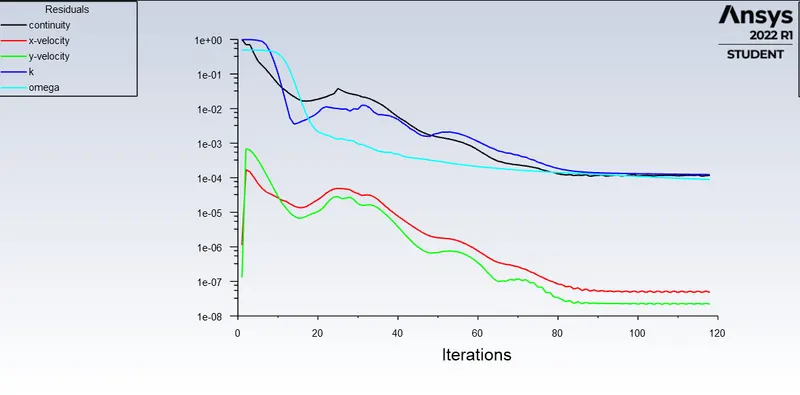
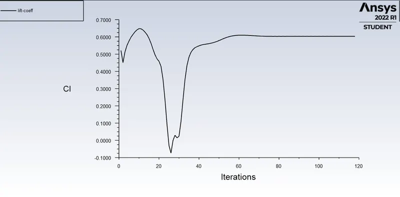
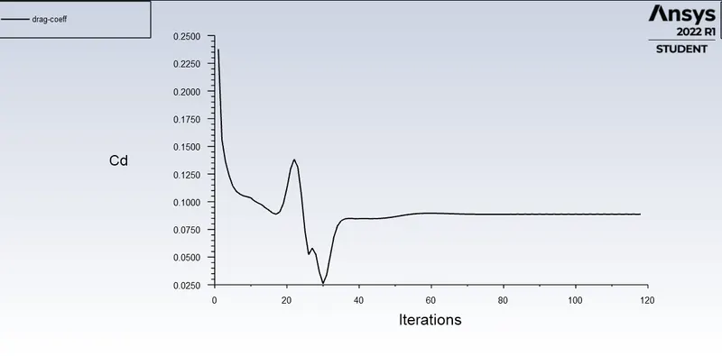
This simulation ran for 118 iterations. These plots were taken in Fluent.
Residuals
The simulation can be said as converged due to low and stable residuals, and due to steady lift and drag coefficients.
Coefficent of Lift
Value: 0.60351
Coefficient of Drag
Value: 0.088709
Summary of Results
| Angle of Attack | Subsonic | Flow | Supersonic | Flow |
| (degrees) | Drag Coefficent | Lift Coefficient | Drag Coefficient | Lift Coefficient |
| 5 | 0.01523 | 0.2194 | 0.0301 | 0.1820 |
| 10 | 0.04462 | 0.4392 | 0.0430 | 0.4272 |
| 15 | 0.00091 | 0.0618 | 0.0887 | 0.6035 |
Variation of Coefficient of Lift by Angle of Attack and Velocity of Flow
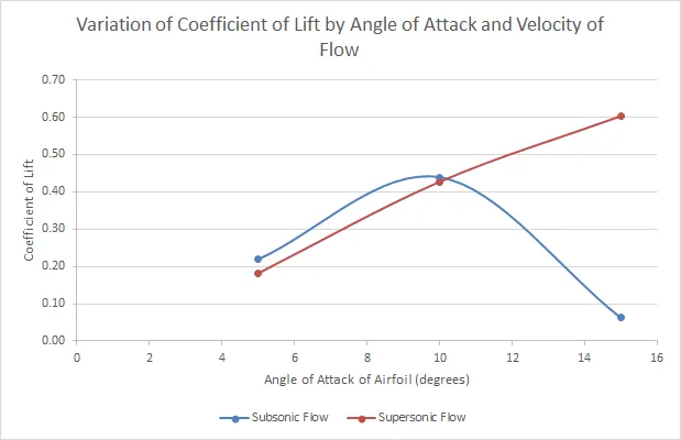
For subsonic flow, the lift generated by the airfoil increases initially but peaks at 10 degrees, and then lift generated falls rapidly, this indicates that the airfoil has passed its stall angle which is somewhere between 10 degrees and 15 degrees for this flow.
This phenomenon is not observed for supersonic flow, this indicates that the stall angle for supersonic velocities is beyond 15 degrees.
Variation of Coefficient of Drag by Angle of Attack and Velocity of Flow
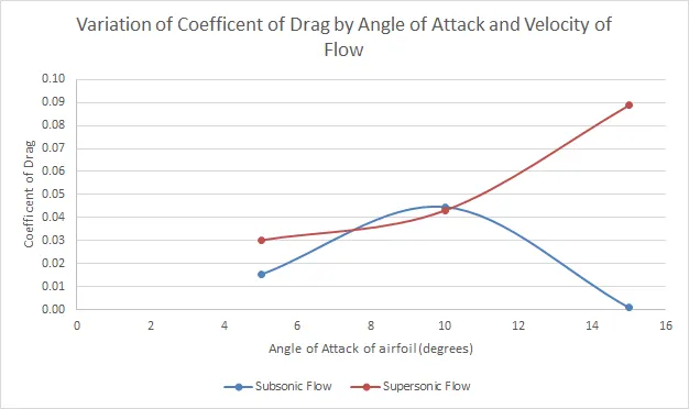
For subsonic flow, the drag experienced by maxes out at 10 degrees and drops rapidly.
While for the supersonic flow, the drag increases with angle of attack, this can be attributed to turbulent flow separation at very high speeds.