Week-7 Challenge: DC Motor Control
1. Explain a MATLAB demo model named ‘Speed control of a DC motor using BJT H-bridge’.
B. Comment on the armature current shoot-up from the scope results.
C. Refer to the help section of ‘The Four-Quadrant Chopper DC Drive (DC7) block’. Compare it with the H-bridge model.
SOLUCTION:
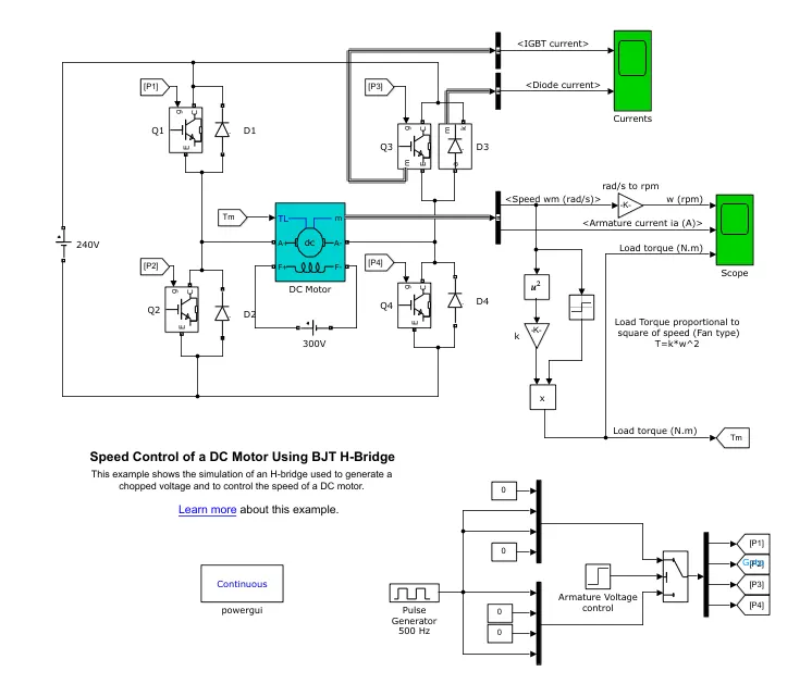
THIS H-BRIDGE MADE UP ON FOUR SWITCHES Q1,Q2,Q3,Q4,AND FOUR DIODES D1,D2,D3,D4.AS IGBT CAN BE USED SWITCHES WHICH CAN BE EIOTHER IN OFF OR ON POSITION .WHEN THE MOTOR IS COASTING IT GENERATES ELECTRICITY DUE TO THE FLEXIBILITY OF THIS.
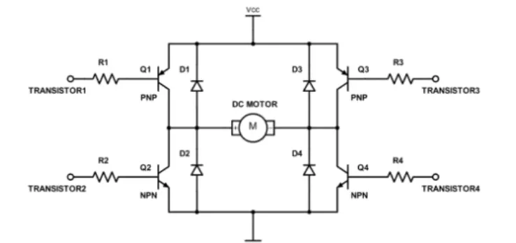
DIFFERENT MODELS AVILBULE:
1.IF THE SWITCH1 AND SWITCH4 IS CLOSED.AND THE CURRENT FLOW THROUGH THE SOURCE.THE SWITCH1.AND THORUGH THE LOADAND THROUG THE SWITCH4.THEN DOWN THE GROUND.THIS NOW AS FORWARD MOTION OF THE MOTOR.
2. if the switch2 and switch3 is closed.in this cause current fllow the source.through the switch3 and through the load.then through switch2.then down the ground.this non as revers motion of the motor.
3. if switch q1.q3 or q2,q4 is closed then both sides of the motor have no potential difference and this is called as broad mode.
4.if only one switch or none are closed in this state the motor will be just coasting.
weorking model:
1. the dc motor uses the present model (5 hp 24v 1750 rpm). it simultes a fan type load. the armuter voltage can be veried from 0to 20v when duty cycle varied from 0to 100%.
2. the bridge consists of four BJT/DIODE PAIRS.
3. TWO TRANSISTERS ARE SWITCHES SIMULTANESLAY:Q1 AND Q2 AND Q3 AND Q4. q1 and q4 are fired.positeve voltage applied to the motor. and diodesD2-D3 OPERATE FREEVELLIG DIODE.AND Q1 AND Q4 SWITCHED OFF.
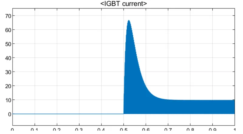
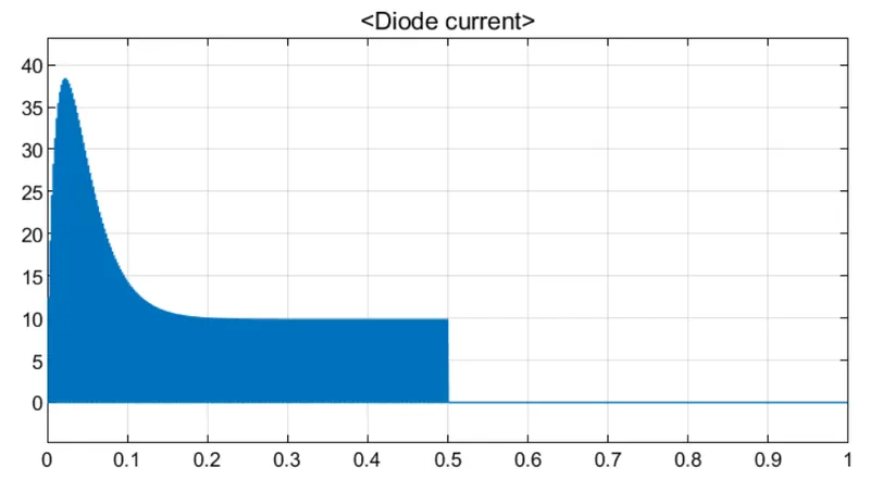
HERE LOAD TORQUE IS PROPORTIONAL TO THE SQUARE OF ANGULAR VELOCITY.
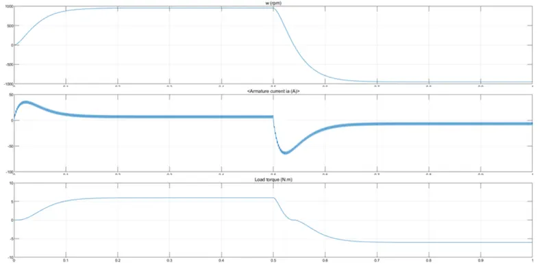
B. Comment on the armature current shoot-up from the scope results.
soluction:
as the principal off pulse width modulaction.(pmw)
the average value of voltage and current fed to the load is controlled by turning the switch between supply and load on and off at a fast rate.the pmw switching frequence has to be high enough not to affect the load.which is to say that resultant wavefrom percevied by load must be as smooth as possible.
the peaks can be remove by reducing the duty cycle.
THE PLOT SHOW THE OUTPUT WHEN THE PULSE WIDTH VALUE IS CHANGED 50%
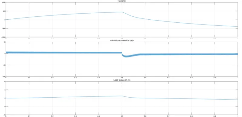
AS THERE IS A PEAK WHEN THE MOTOR IS SWITCHING DIRECTIONS. DUTYCYCLE IS FURTUREV reduced 40% and ouput shows below.
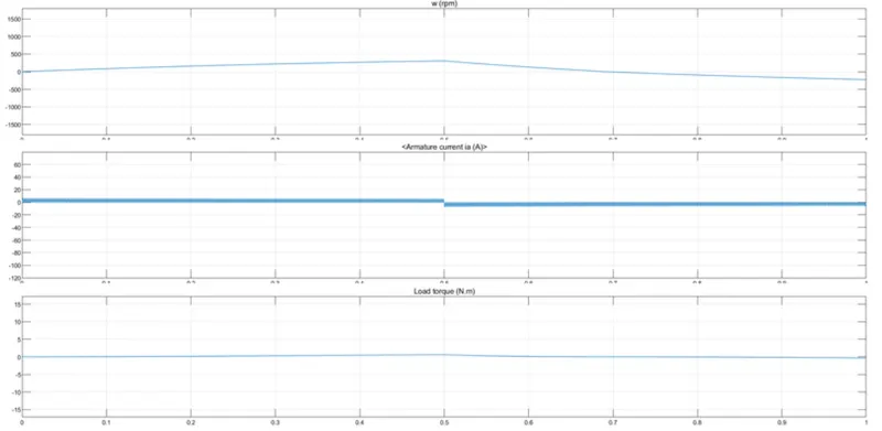
the duty cycle reduced 40% there is no sudden peak in the output.
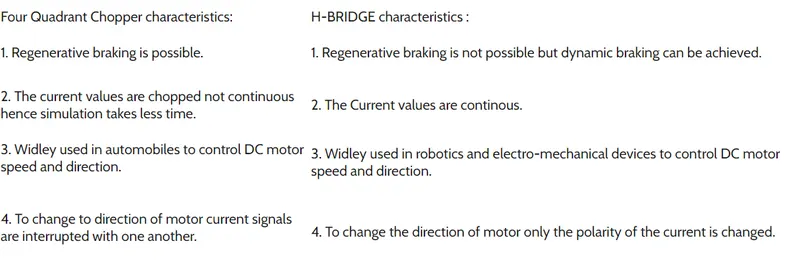
C. Refer to the help section of ‘The Four-Quadrant Chopper DC Drive (DC7) block’. Compare it with the H-bridge model.
soluction:
four quadrant chopper
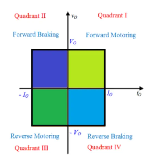
the four quadrant operaction:
Quadrant I
Operation in quadrants 1 and 3 is defined as "Motoring," meaning that speed and torque are in the same direction (both positive or both negative). This typically occurs when a system is driving a load and power is being consumed by the motor.
Quadrant II
Operation in quadrants 1 and 3 is defined as "Motoring," meaning that speed and torque are in the same direction (both positive or both negative). This typically occurs when a system is driving a load and power is being consumed by the motor.
Quadrant III
In the third quadrant, the motor speed and torque both are negative, hence the power is positive. Therefore, the operation of the motor in the third quadrant is known as reverse motoring.
Quadrant III
In the third quadrant, the motor speed and torque both are negative, hence the power is positive. Therefore, the operation of the motor in the third quadrant is known as reverse motoring.
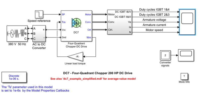
simulink model.
Compare it with the H-bridge model.
2.Develop a 2-quadrant chopper using simulink & explain the working of the same with the relevant results. (Refer to article - Multiquadrant operation of motor )
soluction:
the are two types of qudract choppers the are
type c chopper
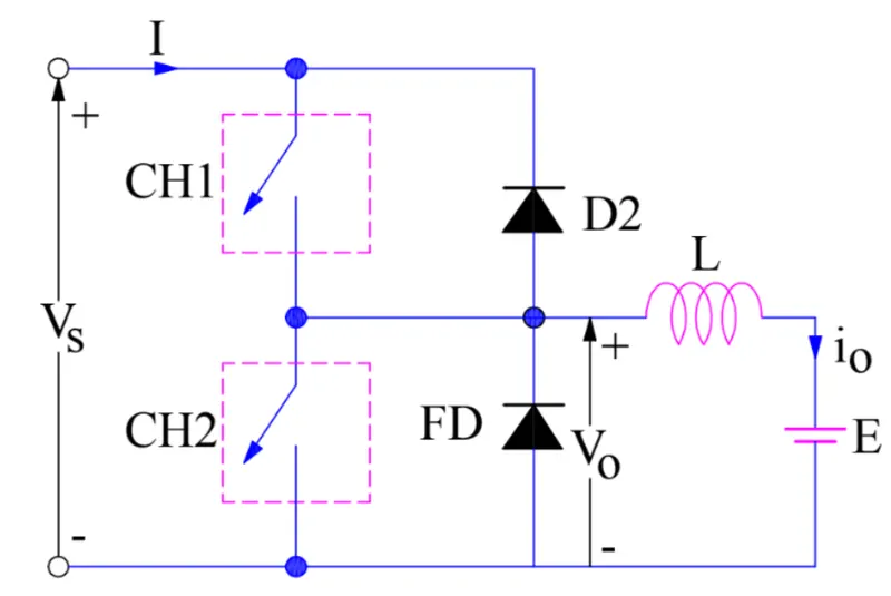
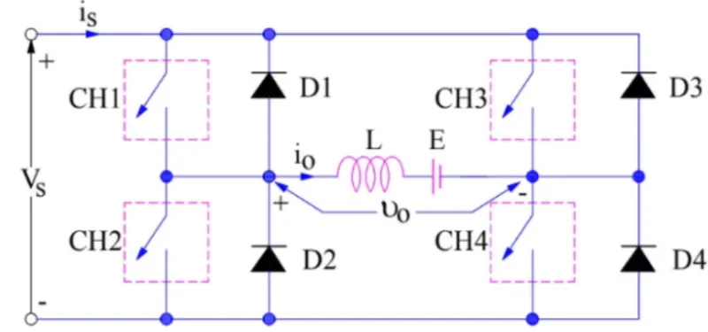
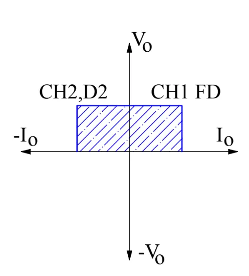
- Class-C or Type-C Chopper is a category of chopper which can operate in first as well as second quadrant. This basically means that, the power can either flow from source to load or load to source in this chopper. This kind of chopper is also known as Two Quadrant Class-A chopper.
- The output voltage Vo is zero when chopper CH2 is ON or free-wheeling diode FD conducts.
- The output voltage Vo is equal to source voltage Vs when chopper CH1 is ON or diode D2 conducts.
- The load current flows in the direction shown in circuit diagram i.e.io is positive when CH1 is ON or FD conducts.
- The load current flows opposite to the direction shown in circuit diagram i.e.io is negative when CH2 is ON or D2 conducts.
- The average load voltage is always positive but the average load current may be positive or negative. Therefore, power flow may be from source to load (first quadrant operation) or load to source (second quadrant operation). The operating region of Class-C or Type-C chopper is shown below by hatched area.
TYPE D CHOPPER:
To understand the operation / working principle of Type-D chopper, let us first have a look at its circuit diagram shown below.
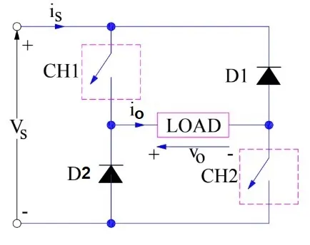
When both the choppers are switched ON, the load is directly connected to source and hence the output voltage Vo will become equal to the source voltage Vs. The current flows from source to LOAD in this case. Thus, both the CURRENT and output voltage i.e. io and vo are positive in this case, hence the operation is in first quadrant.
It should be noted that DIODE D1 and D2 are reversed biased in this case and hence they can be treated as an open switch.
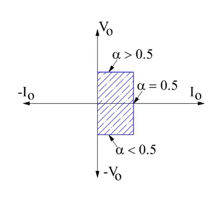
When both the choppers are made OFF simultaneously, the current through the load doesn’t suddenly drops to zero due to INDUCTIVE nature of load. However, it decays gradually and hence a huge amount of voltage is induced in the inductor in the reverse direction (opposite to the direction of vo). This makes diode D1 and D2 forward biased. Thus, D1 and D2 starts conducting and connects the load to source again. But this time, the current flows from load to source (carefully observe the circuit diagram). It shall be noted that, the direction of load current has not changed. The current is still flowing as shown by the direction of io in the diagram but the polarity of vo has changed. Thus, io is positive but vo is negative and hence operation of chopper is in fourth quadrant. The power flows from load to source.
The first and fourth quadrant operation of class-D / Type-D chopper is shown by the hatched area in the figure below.
Various Waveforms:
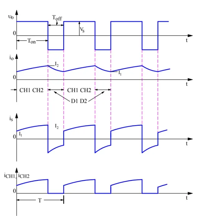
Now, we will discuss the various waveform of class-D or Type-D chopper. Figure below represents various waveforms during the time both the chopper are ON.
3. Explain in a brief about operation of BLDC motor.
SOLUCTION:
THE BLDC motor also consists of two main parts a stator and a rotor. Permanent magnets are mounted on the rotor of a BLDC motor, and the stator is wound for a specific number of poles. Also, a control circuit is connected to the stator winding. Most of the times, the inverter/control circuit or controller is integrated into the stator assembly. This is the basic constructional difference between a brushless motor and a typical dc motor.
A typical controller provides a three-phase frequency-controlled supply to the stator winding. The supply is controlled by logical control circuits and energizes specific stator poles at a specific point of time. This can be understood from the below animations about working of BLDC motors.
Stator windings of a BLDC motor are connected to a control circuit (an integrated switching circuit or inverter circuit). The control circuit energizes proper winding at the proper time, in a pattern which rotates around the stator. Permanent magnets on the rotor try to align with the energized electromagnets of the stator, and as soon as it aligns, the next electromagnets are energized. Thus, the rotor keeps running. The animations below will give you a clear idea of 'how a brushless DC motor works?'
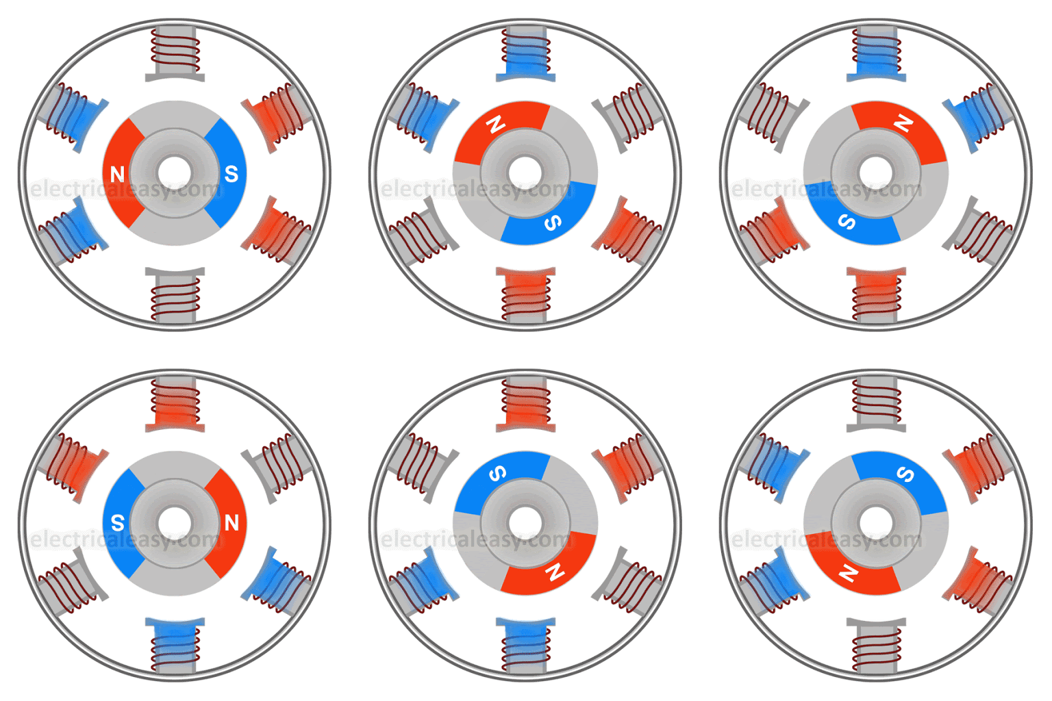 |
Inner rotor BLDC motor working animation |
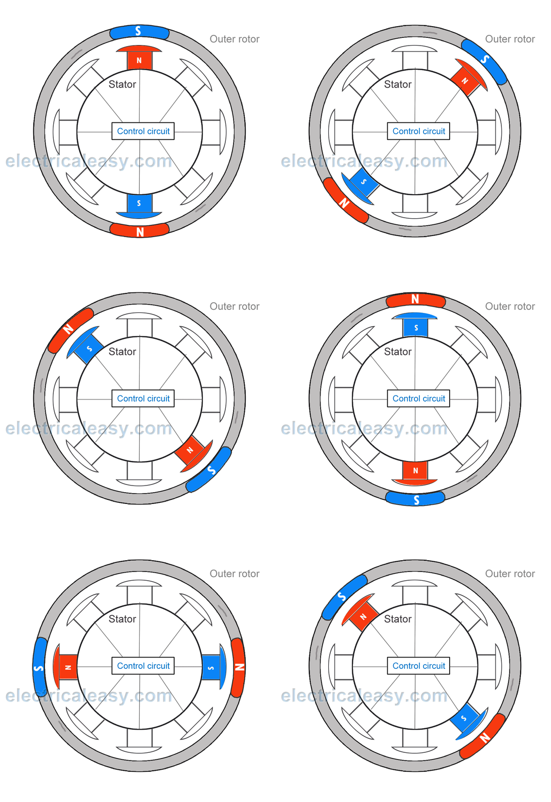 |
| Outer rotor BLDC motor working animation |
Brushless Vs. Brushed DC Motor
- Brushes require frequent replacement due to mechanical wear, hence, a brushed DC motor requires periodic maintenance. Also, as brushes transfer current to the commutator, sparking occurs. Brushes limit the maximum speed and the number of poles the armature can have. These all drawbacks are removed in a brushless DC motor. An electronic control circuit is required in a brushless DC motor for switching stator magnets to keep the motor running. This makes a BLDC motor potentially less rugged.
- Advantages of BLDC motor over brushed motors are increased efficiency, reliability, longer lifetime, no sparking and less noise, more torque per weight, etc.
Applications Of BLDC Motors
BLDC motors fulfill many requirements that a brushed DC motor does. But as they require a complicated control circuit and due to cost considerations, they haven’t yet completely replaced brushed DC motors, especially in low-cost applications. Despite this, there are many applications where BLDC motors dominate –
- Consumer electronics – computer hard drives, small cooling fans, cd/dvd players, etc. and also in modern appliances where quiet operation is desired – such as washing machines, air conditioners, etc.
- Electric Vehicles – many electric vehicles including electric and hybrid cars, electric bikes use BLDC motors.
- They have a wide range of applications in many other areas including robotics, industrial, motion control systems, etc.
ADVANTAGES OF BLDC MOTORS:
1. HIGHER EFFICIENCY AND RELIBILITY
2. LOWER ACOUSTIC NOISE
3. SMALLER AND LIGHTER
4. BETTER SPEED VERSUS TORQUE CHARACTERISTICS
5. HIGHER SPEED RANGE
6. LONGER LIFE
THE END