Week -2
Quaction:
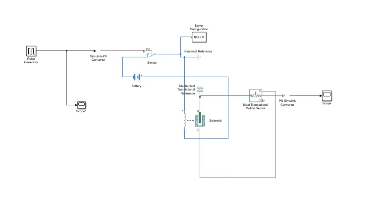
- Make a Simulink model of Doorbell using solenoid block with the following details:
In the above arrangement, when the switch is closed the electromagnet receives electrical power from the battery and pulls the metal arm to hit the bell producing sound.
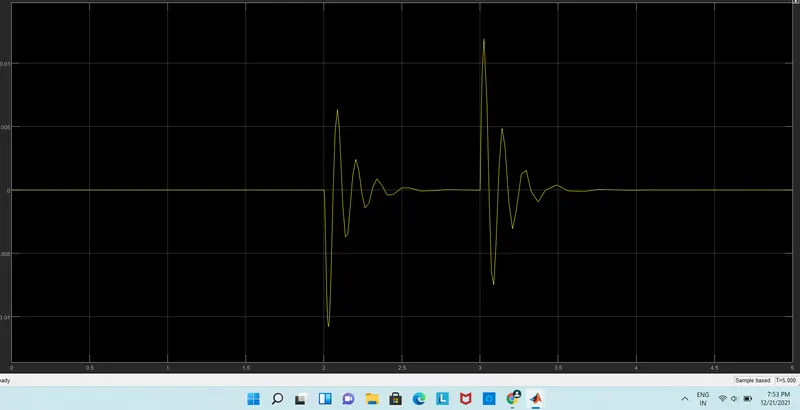
Create a situation where the switch is closed for 2 seconds and then released. Observe the physical movement of the plunger.
Assume remaining parameters.
2. Use a thermistor to sense the temperature of a heater & turn on or turn off the fan as per the below conditions:
Temperature source: 20 °C from 0 to 10 seconds, 27 °C from 10 to 30 seconds, 23 °C from 30 to 50 seconds
Fan conditions: ON if the temperature above 25 °C, OFF otherwise
INPUT:
PULSE GENERATOR:

in this pulse generator block generates square wave pulses at regular intervals. The block waveform parameters, Amplitude, Pulse Width, Period, and phase dealay determine the shape of the output waveform.
scope:

in this block helps from pluse generetion time we have one input port and output port is runing.
soluction:
output
1.ideal translation sensor

The Ideal Translational Motion Sensor block represents a device that converts an across variable measured between two mechanical translational nodes into a control signal proportional to velocity or position. You can specify the initial position (offset) as a block parameter.
The sensor is ideal since it does not account for inertia, friction, delays, energy consumption, and so on.
Connections R and C are mechanical translational conserving ports that connect the block to the nodes whose motion is being monitored. Connections V and P are physical signal output ports for velocity and position, respectively.
The block positive direction is from port R to port C. This means that the velocity is measured as v = vR – vC, where vR, vC are the absolute velocities at ports R and C, respectively.
2.ps.simulink converter.

The PS-Simulink Converter block converts a physical signal into a Simulink® output signal. Use this block to connect outputs of a Physical Network diagram to Simulink scopes or other Simulink blocks.
To convey signal conversion while taking up minimal canvas space, the block icon changes dynamically based on whether it is connected to other blocks.
3.solenoid
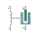
The equation of motion for the plunger as a function of position, x, is:
Fl+m¨x+λ˙x+kx=Fe
where Fe is the electromagnetic force, Fl is the load force, λ is the viscous damping term and m is the plunger mass. The electromagnetic force is related to the solenoid current and inductance by:
Fe=12i2∂L(x)∂x
The inductance, which is derived in [1], can be written as:
∂L(x)∂x=−β(α+βx)2
where α and β are constants. Plugging the preceding equation into the equation for electromagnetic force gives the force-stroke relationship of the solenoid for a current i0:
F=12i02−β(α+βx)2
The Solenoid block solves for α and β by taking the two specified force and stroke measurements and substituting them into the preceding equation. It solves the resulting equations for α and β.
A po sitive current from the electrical + to - ports creates a negative force (i.e., a pulling force) from the mechanical C to R.
4.BATTERY:

The Battery block represents a simple battery model. The block has four modeling variants, accessible by right-clicking the block in your block diagram and then selecting the appropriate option from the context menu,
-
Basic model that does not output battery charge level or simulate thermal effects. This modeling variant is the default.
-
Model with exposed thermal port. This model does not measure internal charge level of the battery.
-
Model with exposed charge output port. This model does not simulate thermal effects.
-
Model that lets you measure internal charge level of the battery and simulate thermal effects. Both the thermal port and the charge output port are exposed.
5.switch.
 The Switch block models a switch 6controlled by an external physical signal. If the external physical signal PS is greater than the value specified in the Threshold parameter, then the switch is closed, otherwise the switch is open.
6.solver function:

in this block represented by a connected Simscape™ block diagram requires solver settings information for simulation.
7.scope

all the blocks connected in the digram shown:
pulse generaction shown in output diagram
2. Use a thermistor to sense the temperature of a heater & turn on or turn off the fan as per the below conditions:
Temperature source: 20 °C from 0 to 10 seconds, 27 °C from 10 to 30 seconds, 23 °C from 30 to 50 seconds
Fan conditions: ON if the temperature above 25 °C, OFF otherwise
soluction:
1.voltage sensor

in this block Connections + and – are electrical conserving ports through which the sensor is connected to the circuit.
2.thermistor:
in this block thermistor represents ntc
thermistor using the B-parameter equation.
R=R0eB(1/T−1/T0)
3.display 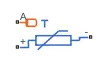
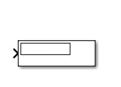
in this block helps from show the values.
4.controlled temperature source
Variable source of thermal energy, characterized by temperature
5.switch

in this block is using The Switch block passes through the first input or the third input signal based on the value of the second input.
6.signal bulder
in this block help from to beld the signals.
7.scope
in this block helps from to show the output wave froms.
all the blocks connected .and diagram shown
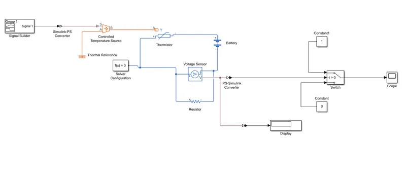
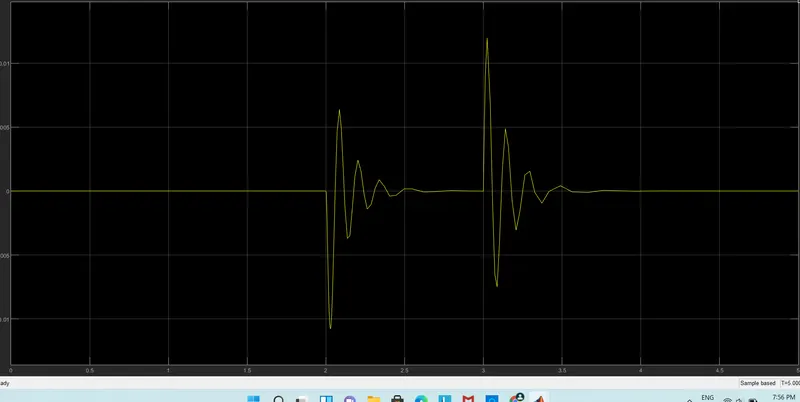
the temperatuer veres the ouput wave from shown in digram
THE END