Week-6 Challenge: EV Drivetrain
1. Which types of power converter circuits are employed in electric and hybrid electric vehicle?
SOLUCTION:.
POWER ELECTRONIC CONVERTER
THE ARE THREEY TYPE CONVERTERS ARE USED IN HEV. THE ARE
AC-DC CONVERTER(ON BORD CHARGER ):IN AC TO DC CONVWRTER ARE COMNLAY USED IN PLUG-IN HYBRID ELECTRIC VEHICLE HEV&PLUG-IN ELECTRIC VEHICLE(PEV) THIS VEHICLES GET POPULSION POWER FROM EXTERNAL ELECTICITY SOURCE WHICH IS ALTERNATING CURRENT. THE BATTERY NEED FROM CHARGING USING DIRECT CURRENT SSOURCE. THIS IS PURPOSE OF ACTO DC CONVERTER IS EMPLOYED IN A PHEV&PEV.
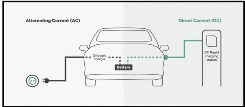
DC-DC CONVERTER:The different configurations of EV power supply show that at least one DC/DC converter is necessary to interface the FC, the Battery or the Supercapacitors module to the DC-link.In electric engineering, a DC to DC converter is a category of power converters and it is an electric circuit which converts a source of direct current (DC) from one voltage level to another, by storing the input energy temporarily and then releasing that energy to the output at a different voltage. The storage may be in either magnetic field storage components (inductors, transformers) or electric field storage components (capacitors).
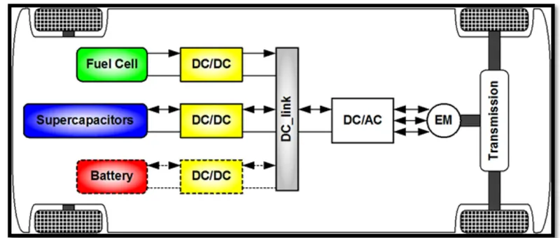
dc-ac converter(inverter):the dc-ac converter is requried to convert the dc power to a sutuble ac power for the electrical meachine.the power output from battery pack is converter using inverter using electric motor.
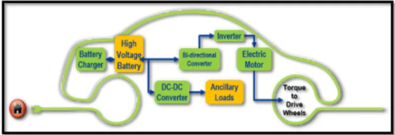
2. An Electric Vehicle's powertrain with 72V battery pack in shown in the diagram below. The duty ratio for acceleration operation is 'd1' and for the braking operation the duty ratio is 'd2'.
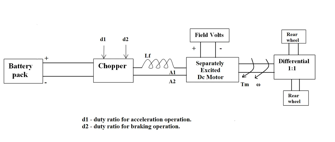
The other parameters of the electric vehicle is given below,
Motor and Controller Parameters:
Rated Armature voltage= 72 V
Rated armature current= 400 A
Ra= 0.5Ω, KΦ= 0.7 Volt second
Chopper Switching frequency= 400 Hz
The vehicle speed-torque characteristics are given by the below equation

What is EV steady state speed if duty cycle is 70%?
soluction:
vehicle output voltage (Vs) IS GIVEN BY
Vv=BATTERY VOLTAGE(v)*duty cycle
Vv=72*0.70
vehicle voltage =50.4v
vehicle torque equaction:
Tv=(Vv-w.k0).k0/Ra
Tv=vehicle torqu(N-m)
Vv=VEHICLE VOLTAGE(VOLTS)
K0=MOTOR CONSTANT
Tv=(50.04-0.7.W).0.7/0.5
Tv=70.56-0.98.W
Tv=24.7+0.00S1.W^2
SOLVING THESE TWO EQUACTIONS,
70.56-0.98.W=24.7+0.0051.W^2
THE QUDRATIC EQUACTION
0.0051.W^2+0.98.W-46.94=0
SINCE QUADRATIC EQUATION WE GOT TWO VALUES
STEADY STATE SPEED OF VEHICLE = 38.85 RAD/S
3. Develop a mathematical model of a DC Motor for the below equation using Simulink.
ω">ωω= V/Kϕ">ϕϕ -Ra/Kϕ">ϕϕ^2 .T
SOLUCTION:
the above equaction is develp in similink model.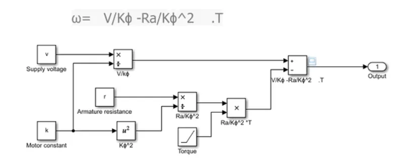
the output speed is shown below
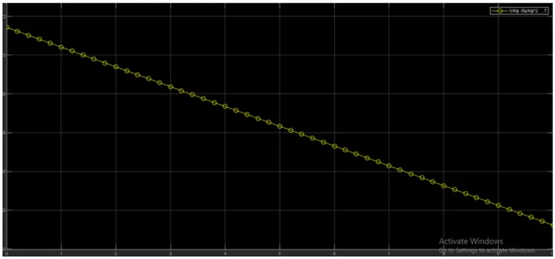
the above plot euaction load is increased and the torqu is decreased in speed.
4.Refer to the blog on below topic:
Induction Versus DC brushless motors by Wally Rippel, Tesla
Explain in brief about author’s perspective.
SOLUCTION:
Both DC brushless and induction drives use motors having similar stators. Both drives use 3-phase modulating inverters. The only differences are the rotors and the inverter controls. And with digital controllers, the only control differences are with control code. (DC brushless drives require an absolute position sensor, while induction drives require only a speed sensor; these differences are relatively small.)
One of the main differences is that much less rotor heat is generated with the DC brushless drive. Rotor cooling is easier and peak point efficiency is generally higher for this drive. The DC brushless drive can also operate at unity power factor, whereas the best power factor for the induction drive is about 85 percent. This means that the peak point energy efficiency for a DC brushless drive will typically be a few percentage points higher than for an induction drive.
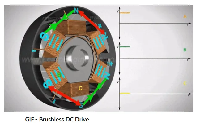
In an ideal brushless drive, the strength of the magnetic field produced by the permanent magnets would be adjustable. When maximum torque is required, especially at low speeds, the magnetic field strength (B) should be maximum – so that inverter and motor currents are maintained at their lowest possible values. This minimizes the I² R (current² resistance) losses and thereby optimizes efficiency. Likewise, when torque levels are low, the B field should be reduced such that eddy and hysteresis losses due to B are also reduced. Ideally, B should be adjusted such that the sum of the eddy, hysteresis, and I² losses is minimized. Unfortunately, there is no easy way of changing B with permanent magnets.
THE END