Week - 4
- Implement control logic of a “washing machine” using Stateflow as per given sequence:
- If the power supply is available, the system gets activated
- If the Water supply is not available, stop the process & indicate through LED
- Soaking time should be 200s followed by Washing time of 100s.
- Then rinsing happens for next 20s & dryer runs for 50s.
solluction:
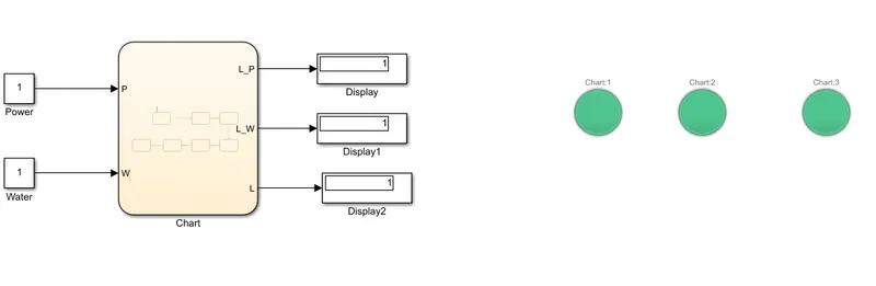
1.power supply:if the power give input 0 condiction supplay is off.if the input 1 means the supply on.and washing machine is on or runing.
2.water supply:if the water supply input 0 condiction washing machine not starts wash.if the water supply input1 means washing machine is to start the calths are washing.
3.LED:condiction 1:power supply 0 means led shown in red light.2 power supply 1means led shows green light.3.water supply input 0 means led shown two lights are red colour.4 water supply means input 1 and the led shows all lights are green colour.
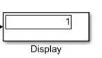
4.display: in this blocks helps from to indicat the values in display.
5.chart: in this chart indicates the working on washing machine.
all the blocks are connected in the digram.
2. Make a Simulink chart for the “Gear shift” logic as per below conditions:
Speed Range(kmph) Gear
0 to 15 1
16 to 25 2
26 to 40 3
41 to 60 4
Above 61 5
Give speed input while the simulation is running & display the gear number.
soluction.
constant: in this blocks helps from show the input value.
slider gan.in this block help from show the speed of the car.
chart: in this block shown car speed and gar condiction shown.
display:in this block helps from to shown the car spped and gar.
all the blocks are connected in the digram shown.

THE END