Week-7 Challenge: DC Motor Control
Aim :- To study DC motor control by applying Verious conditons.
OBJECTIVE :-
1. A. Explain a MATLAB demo model named ‘Speed control of a DC motor using BJT H-bridge’.
B. Comment on the armature current shoot-up from the scope results.
C. Refer to the help section of ‘The Four-Quadrant Chopper DC Drive (DC7) block’. Compare it with the H-bridge model.
2. Develop a 2-quadrant chopper using simulink & explain the working of the same with the relevant results. (Refer to article - Multiquadrant operation of motor )
3. Explain in a brief about operation of BLDC motor.
1. A. Explain a MATLAB demo model named ‘Speed control of a DC motor using BJT H-bridge’.
B. Comment on the armature current shoot-up from the scope results.
In Speed control of DC motor there is some important components to study.
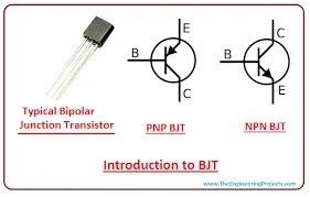
BJT (Bipolar Junction Transistor):-
- The basic Funstion of Bipolar Junction Transistor (BJT) to amplify current, BJTs are used as amplifiers or switches to produce wide applicability in electronic equipment.
- It is a type of transistor that uses both electrons and electron holes as charge carrier.
- A bipolar transistor allows a small current injected at one of its terminals to control a much larger current flowing between two other terminals, making the device capable of amplification or switching.
- BJTs use two junctions between two semiconductor types, n-type and p-type.
- 3 terminals are present in BJT called Collector, Emitter, and Base.
MOSFET (Metal Oxide Semiconductor Field Effect Transistor) :-
- Transistor is a semiconductor device which is widely used for switching and amplifying electronic signals in the electronic devices.
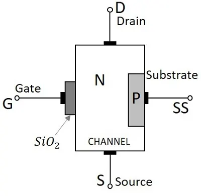
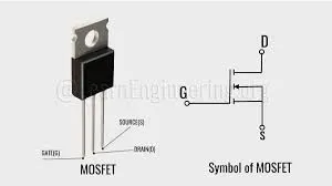
- The MOSFET is a three-terminal device with gate (G), drain (D) and source (S) terminals.
- It works by varying the width of a channel along which charge carriers flow.
- The charge carriers enter the channel at source and exit via the drain. The width of the channel is controlled by the voltage on an electrode is called gate which is located between source and drain.
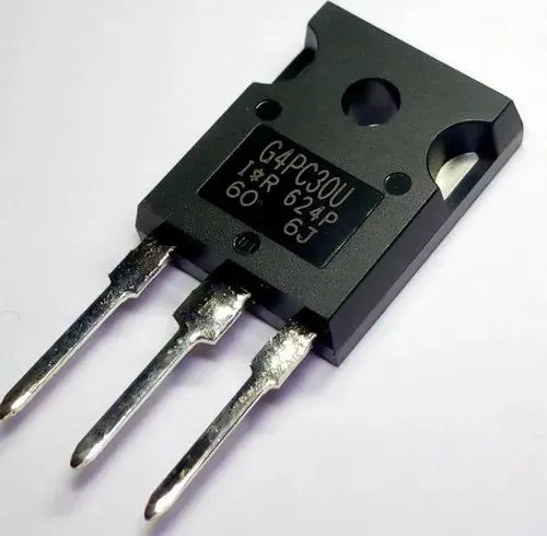
IGBT ( Insulated Gate Bipolar Transistor) :-
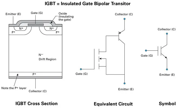
- It is a bipolar transistor with an insulated gate terminal.
- There is a MOS structure and a bipolar power transistor that acts as an output switch.
- IGBTs are suitable for high voltage, high current applications.
- It is an switching device which convert the DC bus voltage to pulse width modulated sinusoidal waveform in VFD.
- It is an power electronic device used for switching.
- An IGBT will switch the current on and off so rapidly that less voltage will be channeled to the motor, helping to create the PWM wave.
Speed control of a DC motor using BJT H-bridge
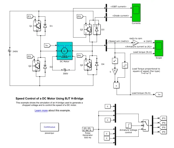
- The DC motor uses the preset model (5 HP 24V 1750 rpm).
- The Bipolar Junction Transistor (BJT) when used for power switching applications, operates as an IGBT.
- When it is conducting (BJT operating in the saturated region), a forward voltage Vf is developed between collector and emitter (in the range of 1 V). Therefore, the IGBT block can be used to model the BJT device.
- It simulates a fan type load (where Load torque is proportional to square of speed).
- The H-bridge consists of four BJT/Diode pairs.
- Two transistors are switched simultaneously: Q1 and Q4 or Q2 and Q3. When Q1 and Q4 are fired, a positive voltage is applied to the motor and diodes D2-D3 operate as free-wheeling diodes when Q1 and Q4 are switched off. When Q2 and Q3 are fired, a negative voltage is applied to the motor and diodes D1-D4 operate as free-wheeling diodes when Q2 and Q3 are switched off.
Motor Rating:-5HP,240V,1750RPM field:300V
Mechanical input to the motor :- Torque(TL)
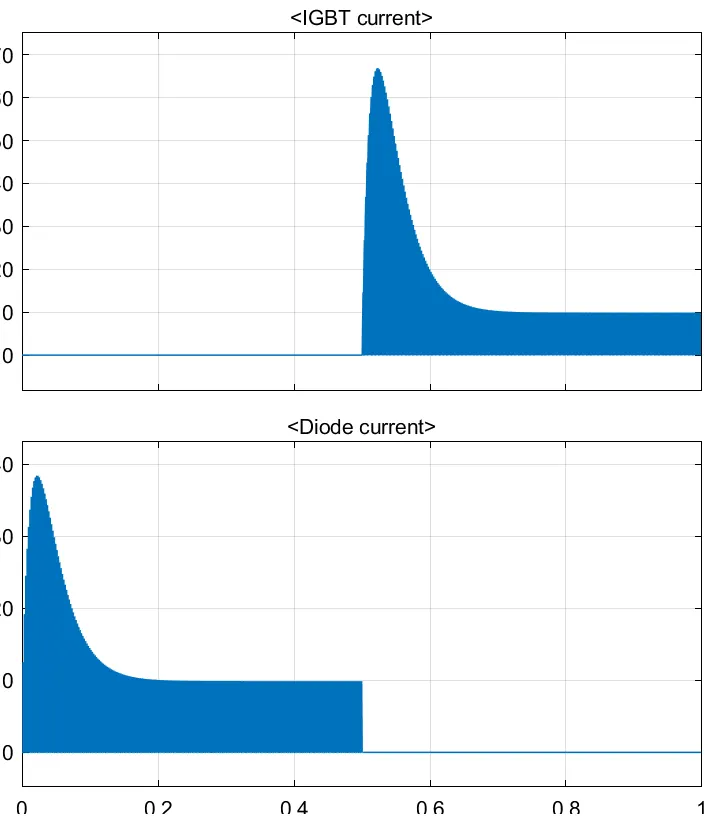
- This graph shows the amount of current flows through the IGBT and DIODE.
- The motor starts in the positive direction with a duty cycle of 75% (mean DC voltage of 180V). At t= 0.5 sec., the armature voltage is suddenly reversed and the motor runs in the negative direction.
By applying input to pulse generator
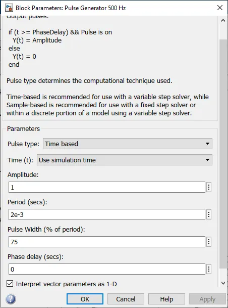
- Amplitude=1
- Pulse Width=75%
- As we run the model with this input we get following out put
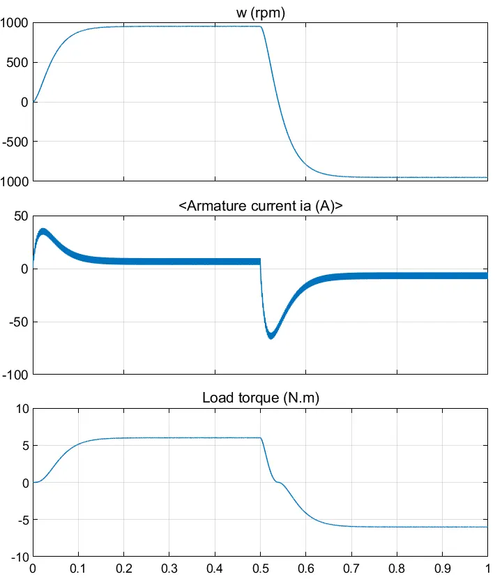
- The Simulink model run for 1sec. That is a one positive and one negetive half cycle in one sec.
- As cycle is started the Speed of motor reaches up to 1000RPM gradually,and motor start running at possitive(Clockwise) direction.
- In positive cycle the torque of the motor is 6 Nm,at starting of the cycle the armature current ia is 40Amp.
- After t=0.5sec, motor start running in negetive (anti clockwise)direction.
- Torque reduces gradually and goes negetive to -6Nm, and speed is 1000 RPM in negetive direction.
We can change input pulse width to 40%
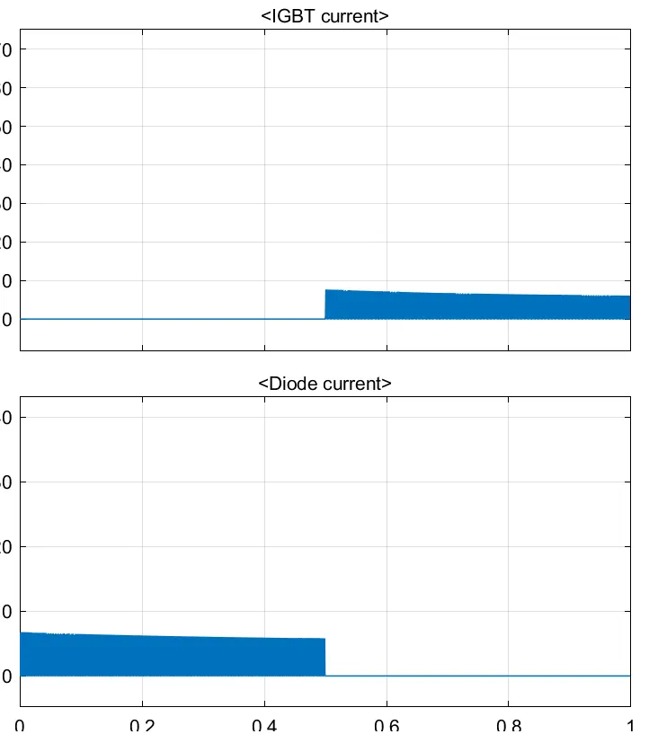
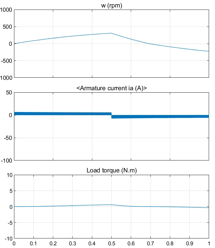
- As we change pulse width to 40%, The armature current ia is very less and constunt.
- The speed of the motor is 300RPM which radually increaces, after t=0.5. motor start rotating in negetive direction and at the end of cycle t=1 the speed reaches 300RPM in negetive direction.
- The torque is almost 0 Nm, it slightly increases in between t=0.4sec to t=0.6 sec.
C. Refer to the help section of ‘The Four-Quadrant Chopper DC Drive (DC7) block’. Compare it with the H-bridge model.
Four-Quadrant Chopper DC motor and four quadrant operation of DC motor (E- Chopper)
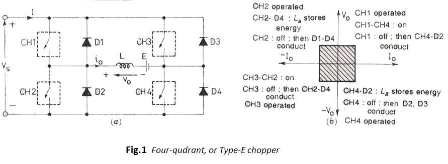
Four-Quadrant Chopper DC motor :-
- This DC motor is classified as class E chopper.
- This circuit constucted by the combination of 2 class C chopper in parallel.
- There are 4 transistor(chopper switch) and 4 diode, connected paraller in pair of 2.
- As Switch CH1 and CH2 is close, CH3 and CH4 will open.
Four quadrant operation of DC motor (E- Chopper)
- 1st Quadrant :- CH1 and Ch2 is switch ON and start conducting. Voltage and current flowing at same direction. So motor rotates in clockwise (positive) direction. 1st quadrant operation called Forward motoring. In this mode inductance store the energy.
- 2nd Quadrant :- CH1 and CH2 switch off, D1 and D4 start conducting. Polarity of voltage and current is opposite. It realized stored power and apply breaking to motor called Regenrative braking.
- 3rd Quadrant :- D1 and D4 Switch off, CH3-Ch4 start conducting. Poarity of voltage current same but opposite to the 1st quadrant.The motor rotates anticlock wise (negetive) direction.
- 4th Quadrant :- Hear by switching off all conducting switches D2-D3 released stored energy. and performe regenerative braking in opposite polarity to the 2nd quadrant.
The Four-Quadrant Chopper DC Drive (DC7) block
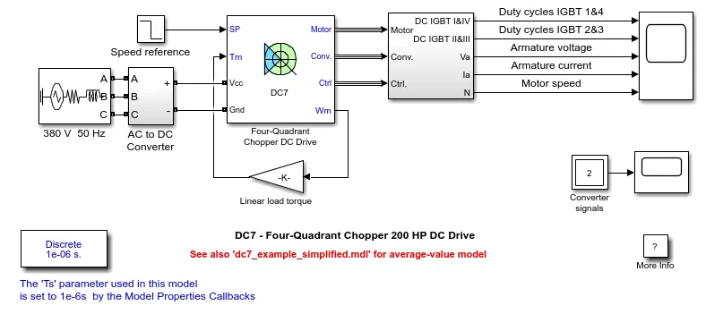
- The 200 HP DC motor is separately excited with a constant 150 V DC field voltage source.
- The converter is fed by a 515 V DC bus obtained by rectification of a 380 V AC 50 Hz voltage source.
- In order to limit the DC bus voltage during dynamic braking mode, a braking chopper has been added between the diode rectifier and the DC7 block.
- The speed regulator outputs the armature current reference (in p.u.) used by the current controller in order to obtain the electromagnetic torque needed to reach the desired speed.
- The speed reference change rate follows acceleration and deceleration ramps in order to avoid sudden reference changes that could cause armature over-current and destabilize the system.
- The current regulator controls the armature current by computing the appropriate duty ratios of the 5 kHz pulses of the four IGBT devices (Pulse Width Modulation). For proper system behaviour, the instantaneous pulse values of IGBT devices 1 and 4 are opposite to those of IGBT devices 2 and 3.
- This generates the average armature voltage needed to obtain the desired armature current.
- In order to limit the amplitude of the current oscillations, a smoothing inductance is placed in series with the armature circuit.
OUTPUT :-
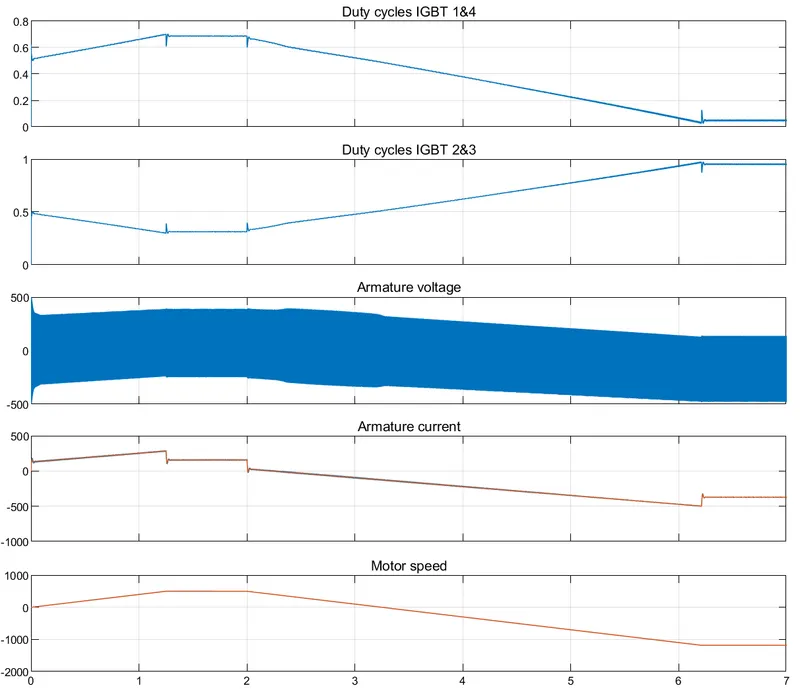
Comparison of BJT H-bridge and The Four-Quadrant Chopper DC Drive (DC7) block
| BJT H-bridge | Four-Quadrant Chopper |
|
The polarity can be changed to reverse the rotating direction of the motor. |
The motor runs in four quadrants performs forward and reverse motoring, regenrative and reverse regenerative braking. |
|
The motor speed can be change by changing the pulse width. |
The motor speed can be change by changing the speed reference value. |
|
Input source is DC. |
Input source is AC and it will rectify in veriable DC. |
|
PI controller is absent. |
PI controller is used to control Speed and current. |
|
It has low efficiency. |
It has high efficiency than BJT H bridge. |
|
Armature current is shoot up during the phase transition. |
Armature current is does not shoot up but the low voltage value is negligible. |
|
To change rotation direction of the motor polarity of of power supply need to be change. |
In this we need to interrupt one signal under control of other to change rotation direction of motor. |
|
High maintainance is needed. |
Low maintainance is needed as compair to the H bridge. |
|
Output signal is contious. |
Output signal is discrete. |
2. Develop a 2-quadrant chopper using simulink & explain the working of the same with the relevant results.
2-quadrant chopper is nothing but the C-type chopper.
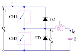
- The input Avarage voltage is will be always possitive, but the avarage load current is be negetive or positive.
- Switch CH1 and CH2 is not switch ON at the same time because it leads to short circuit in supply line.
- C-chopper is used for regenerative braking and motoring opration.
- The output voltage Vo is always positive as freewhiling diode is connected across load.
- When switch CH1 is on current flows from source to load.The inductance store energy.
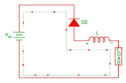
- When CH1 is close freewhiling diode start conducting and output voltage Vo is equal to Vs. The direction of the current io will be reversed .The current io will be flowing towards the source.
- The load current will be negetive when CH2 is ON. The diode completes its path when it flows through diode D2.
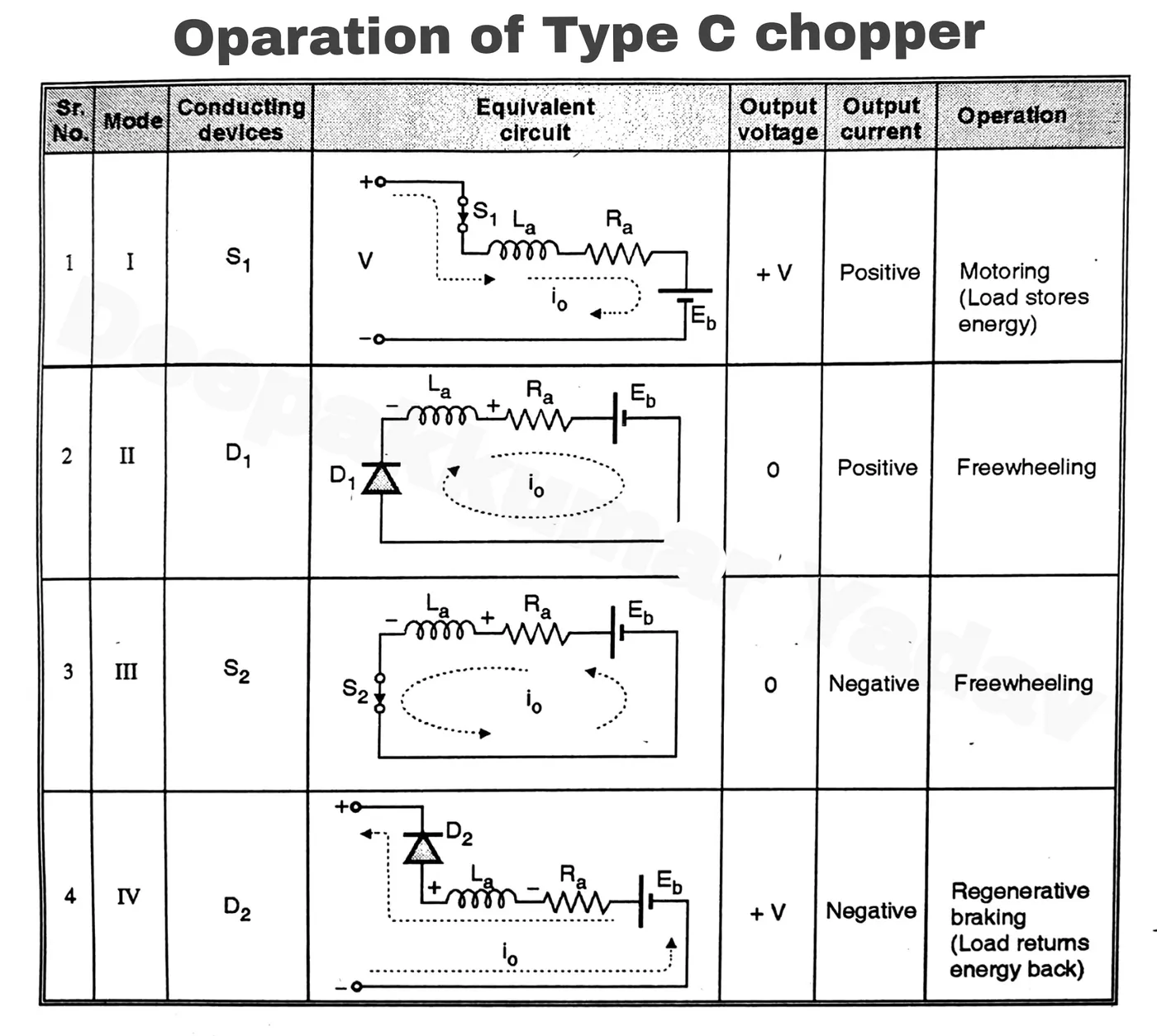
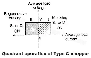
- A class C chopper can either work in first or second quadrant.
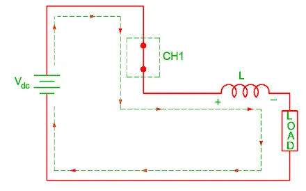
1. Mode I (S1 turned ON)
- As witch S1 is turned on, the DC supply gets connected across the load making the load voltage positive (V0 = + V).
- The load current flows from the dc supply to the load. Thus load voltage and load current both are positive and load receives power from the source.
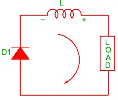
2. Mode II (S1 turned OFF/ D1 starts conducting)
- As S1 is turned off, due to sudden interruption of load current, a negative self induced emf (L di / dt) appears across the load inductance.
- This will forward bias diode D1 and freewheeling takes place through it.
- After sometime the freewheeling current reduces to zero, and D1 turns off. Load voltage is zero and load current is positive in this mode of operation.
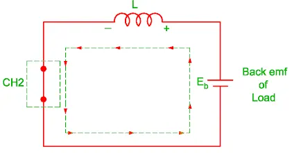
3. Mode III (D1 turns OFF/ S2 turned ON)
- S2 can be turned on only after D1 goes out of conduction. S2 can be turned on due to the presence of the back emf Eb in the circuit.
- The load voltage is zero and load current becomes negative in this mode of operation.
4. Mode IV (S2 turned OFF/ D2 starts conducting)
- D2 comes into conduction as soon as S2 is turned off.
- The stored energy is returned back. The motor acts as a generator. The load voltage is positive (vo = V) but load current is negative in this mode of operation.
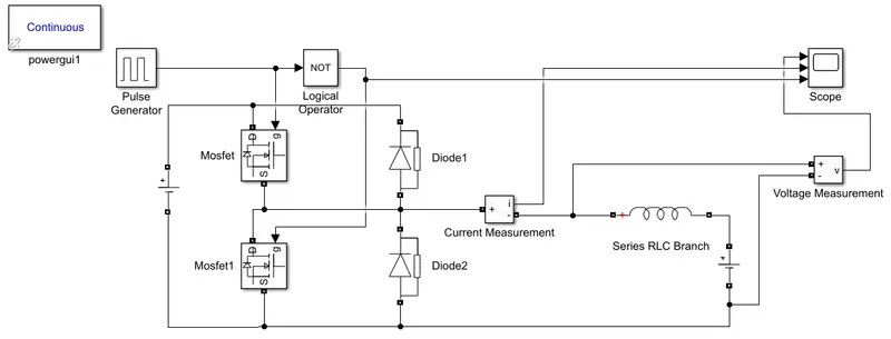
Constucting C-Chopper in simulink
Components:-
- Pulse Generator
Input:-
Amplitude=1, Time period=0.02sec, pulse width =50%
- MOSFET
- Diode
- Inductor
- Logic operator

- Power GUI
- Current Measurement

- Voltage Measurement

- DC Voltage source
DC1=24, DC2=12

- Scope

Simulink Model:-
 |
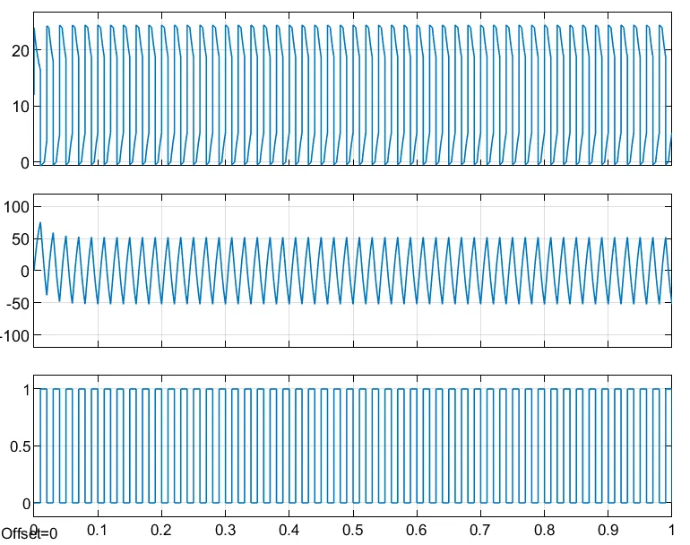
OUTPUT:-
3. Explain in a brief about operation of BLDC motor.
- A brushless DC electric motor is also known as an electronically commutated motor or synchronous DC motor.
- A synchronous motor using a DC power supply.
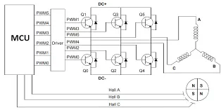
- It uses an electronic close loop controller to switch DC currents to the motor winding producing magnetic fields which effectively rotate in space and which the permanent magnet rotor follows.
- The controller adjusts the phase and amplitude of the DC current pulses to control the speed and torque of the motor.
- This control system is an alternative to the mechanical commutator (brushes) used in many conventional electric motors.
- The construction of a brushless motor system is typically similar to a permanent magnet synchronous motor (PMSM), but can also be a switched reluctance motor, or an induction (asynchronous) motor.
CONSTRUCTION
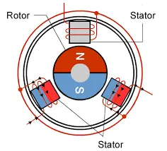
- In this motor, the permanent magnets attach to the rotor. The current-carrying conductors or armature windings are located on the stator.
- They use electrical commutation to convert electrical energy into mechanical energy.
- The main design difference between a brushed and brushless motors is the replacement of mechanical commutator with an electric switch circuit.
- A BLDC Motor is a type of synchronous motor in the sense that the magnetic field generated by the stator and the rotor revolve at the same frequency.
- Brushless motor does not have any current carrying commutators.
- The field inside a brushless motor is switched through an amplifier which is triggered by the commutating device like an optical encoder.
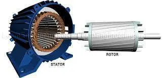
There are two main components called Stator and Rotor.
Stator:-
It consist of stacked steel lamination with windings placed in the slots that are auxillary cut along the inner periphery.
Rotor:-
This is made up of permanent magnetand can vary from two to eight pairs with alternate north(N) and south(S) poles. Ferriet magnet Rare earth alloy magnets are used in rotor.
Circuit diagram
WORKING PRINCIPLE
- BLDC motor works on the principle similar to that of Brushed DC motor.
- The Lorentz force law which states that whenever a current carrying conductor placed in a magnetic field it experiences a force. As a consequence of reaction force, the magnet will experience an equal and opposite force.
- In the BLDC motor, the current carrying conductor is stationary and the permanent magnet is moving.
- The armature, which rotates and contains an electromagnet, is called the rotor.
- In a brushed DC motor, the rotor spins 180-degrees when an electric current is run to the armature.
- The brushes, as the rotor spins, make contact with the stator, flipping the magnetic field and allowing the rotor to spin a full 360-degrees.
- A brushless DC motor is essentially flipped inside out, eliminating the need for brushes to flip the electromagnetic field.
- In brushless DC motors, the permanent magnets are on the rotor, and the electromagnets are on the stator.
- A computer then charges the electromagnets in the stator to rotate the rotor a full 360-degrees.
ADVANTAGES
- Less overall maintenance due to absence of brushes.
- Reduced size with far superior thermal characteristics.
- Higher speed range and lower electric noise generation.
- It has no mechanical commutator and associated problems.
- High efficiency and high output power to size ratio due to the use of permanent magnet rotor.
- High speed of operation even in loaded and unloaded conditions due to the absence of brushes that limits the speed.
- Long life as no inspection and maintenance is required for commutator system.
- Low noise due to absence of brushes.
LIMITATIONS
- These motors are costly.
- Electronic controller required control this motor is expensive.
- Requires complex drive circuitry.
- Need of additional sensors.
APPLICATIONS
- Electric vehicles, hybrid vehicles, and electric bicycles.
- Industrial robots, CNC machine tools, and simple belt driven systems.
- Washing machines, compressors and dryers.
- Fans, pumps and blowers.