Week -2
OBJECTIVE:-
- To Create a situation where the switch is closed for 2 seconds and then released. and to observe the physical movement of the plunger.
- Use a thermistor to sense the temperature of a heater & turn on or turn off the fan as per below conditions:-
- Temperature source: 20 °C from 0 to 10 seconds, 27 °C from 10 to 30 seconds, 23 °C from 30 to 50 seconds.
- Fan conditions: ON if the temperature above 25 °C, OFF otherwise.
I. To Create a situation where the switch is closed for 2 seconds and then released, and to observe the physical movement of the plunger.
SIMULINK MODEL:-
CONSTUCTION AND WORKING:-
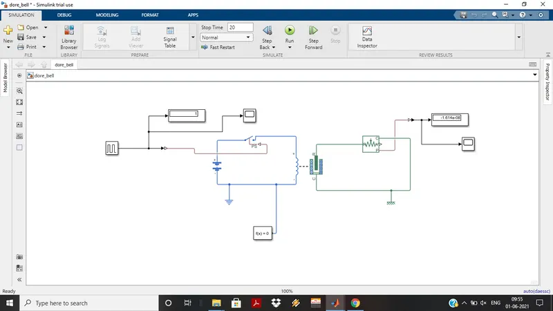
- As per requirment the switch has to close for 2 sec and then released. To satisfy such condition PULSE GENERATOR is used as an input. This pulse generator is set with some modified values like ampilude=1,period=4sec, pulse width=50%.which can helps to get required result.
- It's connected to the DISPLAY which is showing amplitude value. A SCOPE is connected simultaneously which gives a graph for 20 sec (performing time).
- Further this input is connected to the processing block with SWITCH.
- Other two ports of switch are connected with the BATTERY and SOLENOID.
- To varify the output IDEAL TRANSLATION MOTION SENSOR is connected, which provides the out put value as well as graph on scope.
- The configuration input is also needed to calculate the out put value. It is connected to the processing blocks.
INPUT SIGNAL:-
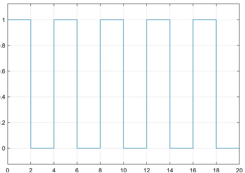
- The input signal shows the closing and swithing ON of the switch in time duration of 4 sec. That means it switch OFF for 2 sec and then ON.
- The input is in continuous form.
OUTPUT:-
- We need to find the physical moment of the plunger so we connected motion sensor along with the solenoid. Which can sense the moment and convert it into physical out put.
- This output then displayed on scope as well as in digital value by connecting an inter link called PS-SIMULINK CONVERTOR.
- As we give the time duration of 20 sec. The stop time value is displayed on digital display that is -1.614e-08 which is nothing but the output vibration of the system. Here the real value is 08 which is our output value for 20th sec.
- Output wave form is produce as follow:-
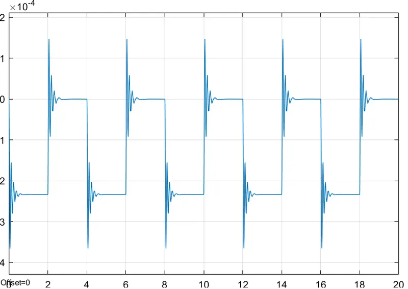
The graph represents the motion of plunger. As switch is of plunger needed approximately half sec of time to completely back to steady possition. This is becsuse of self genereted force on the plunger due to applyed force.
CONCLUSION:-
From the above wee stuided the use of solenoid block in Dore Bell structure with waiting time of 2 sec.
II. Use a thermistor to sense the temperature of a heater & turn on or turn off the fan as per below conditions:
Temperature source:
- 20 °C from 0 to 10 seconds
- 27 °C from 10 to 30 seconds
- 23 °C from 30 to 50 seconds
Fan conditions:
- ON if the temperature above 25 °C, OFF otherwise.
SIMULINK MODEL:-
CONSTUCTION AND WORKING:-
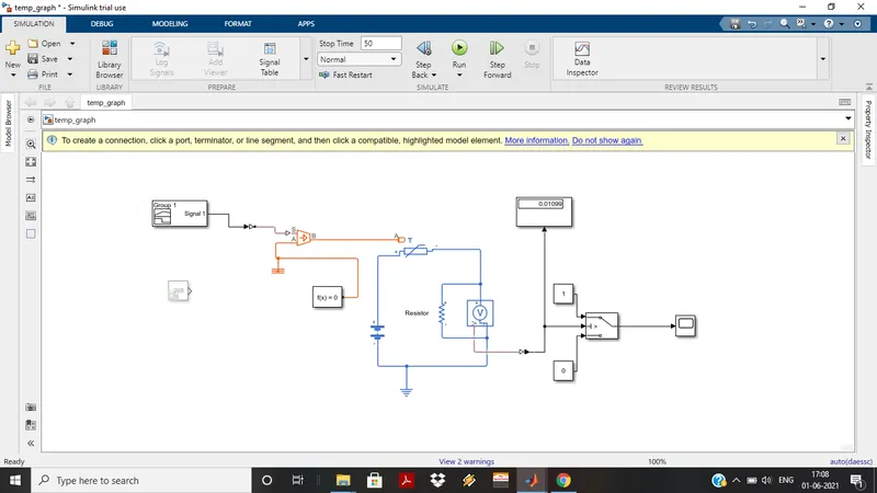
- At input side SIGNAL BUILDER is the main simulink block. With the help of this required conditions can be satisfied.
- Along with signal builder CONTROLLED TEMPERATURE SOURCE is connected.This block represents the ideal source of thermal energy it can maintain the specified temperature difference across the source in meaning of heat flow through the system.
- futher it is connected to the process block that is THERMISTOR. Which is temperature control device. It has 2 electrical ports which are connected to the BATTERY and VOLTAGE SENSOR.
- Voltage sensor takes the voltage between any electrical circuit and convert it in to physical signal with respect to the voltage. The resistsnce is connected parallel to the voltage sensor. this resistance is nothing but the Bipass resistance.
- On output side THRESHOLD SWITCH is conected. This swich is further connected with DISPLAY as well as SCOPE. By which we can study the result.
INPUT:-
For the input there are some specified conditions as follow:-
- 20 °C from 0 to 10 seconds
- 27 °C from 10 to 30 seconds
- 23 °C from 30 to 50 seconds.
- Fan condition:- ON if the temperature above 25 °C, OFF otherwise.
For satisfing above conditions Signal Builder is used. In that we can build the conditions graph as per our requirment. So the input signals are as follow:-
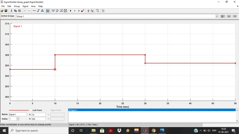
here we can see one of the point of condition which is at 10sec the temperature is 20 °C,which is converted in to kelvin ie.293k. This input is given to the thermistor.
There is one more input as constant block to find out contant value at 25°C at which the fan is has to be turn ON.
OUTPUT(RESULT):-
- Thermistor is connected to the voltage sensor and battery so the signal gets converted in to electrical physical signal with respect to the voltage.
- On out put side there is Theshold swich which feeded with threshold value obtained by connecting one constant block with 298kelvin (25°C) which is nothing but the Fan's turn ON temperature in input side by comment out the signal builder.
- 0.01189 this value comes from constant input which feeds as threshold value.
- Again connecting the signal builder block final output is comes out.
- Digital value is obtained at output is 0.01099 which is value of the 50th sec where the simulink stop.
- Scope shows the outpot graph as follows:
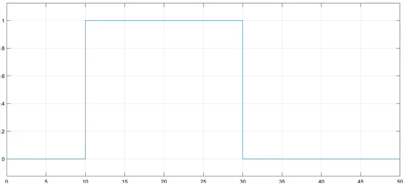
- Graph shows the Turn ON and Turn OFF condition of FAN at perticular event of time and temperature.
- Fan remains turn OFF in duration 0-10 sec and 30-50 sec because the temperature on that time period is 20°C and 23°C respectively.
- Fan only turn ON in duration 10-50 sec where the temperature is 27°C.
- The graph form by satisfing all the conditions and we get the final result of the simulink model.
CONCLUSION:-
From above we stuided the use of Signal Builder which can build the signal on command as per we needed, Thermistor which electrothermal device.