Week-11 Challenge: Braking
1. For a defined driving cycle, calculate the energy required for braking.
In any vehicle acceleration and declaration is much important. I we need to drive the vehicle from one place to another we need acceleration but to stop the vehicle we need brakes which acts deceleration on vehicle. As we required to stop the vehicle in stipulated time, but we are not allow to stop the vehicle at its inertia value so we need to apply brakes .When we apply the brakes amount energy is utilized by vehicle, this energy utilization is depends on the driving cycle in which vehicle is driven at that moment.
The formula for Energy reqired for braking is same as of acceleration.
`E n ergy (dec)=1/2*MV^2`
Where,
M= total mass of vehicle
V=speed of vehicle
The EUDC (Extra Urban Driving Cycle) segment has been added after the fourth ECE cycle to account for more aggressive, high speed driving modes. The maximum speed of the EUDC cycle is 120 km/h. An alternative EUDC cycle for low-powered vehicles has also been defined with a maximum speed limited to 90 km/h.
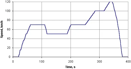
Figure: EUDC Cycle
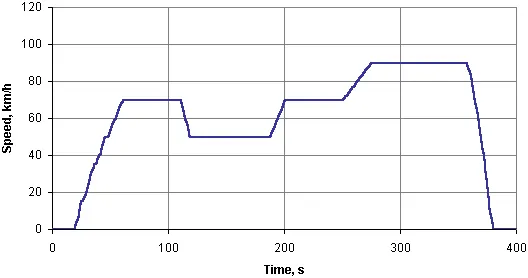
Figure: EUDC Cycle for Low Power Vehicles
Emissions are sampled during the cycle according to the constant volume sampling (CVS) technique, analyzed, and expressed in g/km for each of the pollutants.
The following table includes a summary of selected parameters for the ECE 15, EUDC and NEDC cycles.
|
Characteristics |
Unit |
ECE 15 |
EUDC |
NEDC† |
|
Distance |
km |
0.9941 |
6.9549 |
10.9314 |
|
Total time |
s |
195 |
400 |
1180 |
|
Idle (standing) time |
s |
57 |
39 |
267 |
|
Average speed (incl. stops) |
km/h |
18.35 |
62.59 |
33.35 |
|
Average driving speed (excl. stops) |
km/h |
25.93 |
69.36 |
43.10 |
|
Maximum speed |
km/h |
50 |
120 |
120 |
|
Average acceleration1 |
m/s2 |
0.599 |
0.354 |
0.506 |
|
Maximum acceleration1 |
m/s2 |
1.042 |
0.833 |
1.042 |
For calculation of braking energy of vehicle in Extra Urban Driving Cycle
Total Weight of vehicle =1200 Kg
Initial velocity (speed) = 80 kmph
Final velocity (speed) = 0 kmph
Declaration time = 10 sec and 20 sec
Calculating with these inputs vehicle exibits 0.01235 kWh for 10 sec of time duration and 0.00617 KWh for 20 sec of time duration.
In time duration of 10 sec 0.1235 KWh energy is utilize in 1 sec by the vehicle.
2. Why electric motor can’t develop braking torque at high speed similar to starting? How electric and mechanical brakes are coordinated?
- Why electric motor can’t develop braking torque at high speed similar to starting?
When we start the vehicle motor on that time motor is at stand still (OFF) condition, so when it started it provides maximum torque to the vehicle to reach its maximum speed. Because of the motor is already given the high torque it cant be produce at the time of deceleration. So the electric motor can’t develop braking torque at high speed similar to starting. The braking operation is happends in two ways electric braking and mechanical braking.
- How electric and mechanical brakes are coordinated?
Electric braking (Regenrative Braking) :-
When the speed of the motor is increased than the synchronous speed, then the regenerative braking is used. When the rotor rotates higher than the speed of the synchronous speed, then the motor acts as a generator and the directions of current flow and the torque are reversed. Hence the generator is stopped by braking.
- The main disadvantage is, when the motor exceeds the synchronous speed, it is possible of mechanical and electrical damage. So, regenerative braking can be done at the sub-synchronous speed only when the variable frequency source is applied.
An inverter is used to return excess energy back to the three-phase supply rather than the dissipation of energy in the resistor. To drive the variable frequency systems, an inverter is connected in parallel to the rectifier.
Mechanical braking (Classical brakes with hydraulic cylendrical system) :-
The hydraulic braking system uses liquid as a pressure for the movement or force or to increase the force. The pressure applied on a liquid can be called as hydraulic pressure. This type of braking system works on the principle of pascal’s law. In this type, when the force is applied on the pedal, it is converted to hydraulic pressure by using a master cylinder/liquid. This hydraulic pressure helps in braking the vehicle by transferring pressure to the final brake drum or disc rotor via braking lines. It ensures that the braking effect is the same on all the four/two wheels.
- In regenrative braking brake torque is not same as the acceleration torque therefore the regenerative braking can not happen so effectively that we can not get all the power back to the battery.
- The battery can except typical charging current. At the time of acceleration battery can discharge at double rate but at the time time of charging it is lowest is peak discharge rate.
- To get power back to the battery we must have by directional power converter therefore power converter is also become complex in nature.
- So using only one braking system is not much efficient to vehicle.
- There is two Brake control strategies.
- Series:-
There is series conection of both electrical and mechanical beake systems. There is again two conditions of applying series brake i) depends on driver choice, ii)depend on need of brake behaviour.
Recovery of the energy is different. In series we apply the mechanical then regenerative (electrical) brake one after another. We can apply only one brake at a time.
- Parallel:-
In this strategy we can apply both mechanical and electrical brake simultaniously that means both at the same time.
When the brake padel is pressed the hydraulic fluid reaches to the piston of brakes and create the braking pressure on the wheel,the produced kinetic energy by the wheel is been used for regeneration of energy by using bi directional motor.
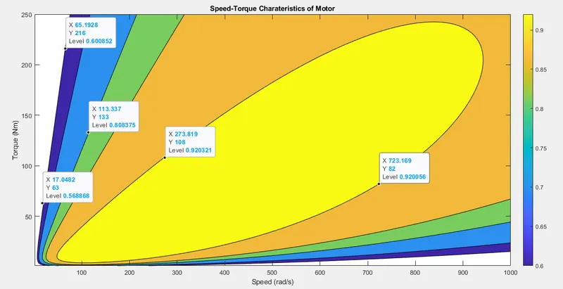
3. Make a MATLAB program which plots contour of given motor speed, torque and efficiency values. Attach the code as a .m file attach a screenshot of all the plots.
MATLAB Program:
%motor speed, torque and efficiency values
clear all
clc

x = linspace(1,1000,250); %speed rad/sec
y = linspace(1,250,250);  % torque Nm

%motor loss constants
Lc = 0.2; % copper loss constant
Li = 0.008; % iron loss constant
Lw = 0.00001; % windage loss constant
Lk = 20; %Constant loss

[X,Y] = meshgrid(x,y); % converting to 2D
Po = (X.*Y); %Output power = Speed*Torque

C = (Y.^2)*Lc; %copper loss
L = X.*Li; %iron loss
W = (X.^3)*Lw; % windage loss

Pi = Po + C + L + W + Lk;
Efficiency = Po./Pi; %efficiency of motor
V = [0.60,0.70,0.81,0.86,0.92,0.98]; %Eifficiency to be plotted
box off
grid off

contourf(X,Y,Efficiency,V);
contourcbar
title('Speed-Torque Charateristics of Motor');
xlabel('Speed (rad/s)');
ylabel('Torque (Nm)') ;- x,y values are given as speed (rad/s) and Torque (Nm) respectively.
- Motor parameters like motor losses, input power , Output Power, Efficiency are given.
- Efficency=output power / input power
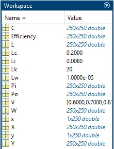
Workspace:-
OUTPUT :- shows contour graph