Week-6 Challenge: EV Drivetrain
1. Which types of power converter circuits are employed in electric and hybrid electric vehicle?
There are six types of power converter circuits used in power electronics
- Diode rectifier.
- AC-DC converters (controlled rectifier)
- AC-AC converters (AC voltage controller)
- DC-DC converters (DC choppers)
- DC-AC converters (Inverters)
- Static switches.
Diode rectifier
This converters AC power into fixed DC power. The applied input voltage can be single-phase or three-phase. The input alternating voltage is converted into a steady & smoother DC output.
AC-DC converters (controlled rectifier)
This type of converters is also known as a controlled rectifier. The applied AC signal converted into DC signal using controlled switches (Thyristors). Four natural commutated thyristors are used in this circuit instead of diodes.
AC-AC converters (AC voltage controller)
These converters convert the fixed AC source into variable AC output voltage. By varying the conduction time of TRIAC, the output voltage of converter can be controlled directly. AC-AC converters are also known as AC voltage controllers.
DC-DC converters (DC choppers)
DC-DC converters convert or change the voltage level of applied DC input into a DC output. These converters are also known as choppers, or a transistor chopper, or switching regulator.
The average output voltage of the converter circuit can be directly controlled by changing the conduction time of the controlled switch. The conduction time t of the switch is the product of the duty cycle and chopping period.
t = DT
Where D is the duty cycle of the chopper and T is the chopping period.
DC-AC converters (Inverters)
DC-AC converters convert the input DC power into AC power. These converters are also known as inverters. There are a lot of different types of inverters. The alternating switching of the thyristors provides an alternating current through the load. The output voltage of the circuit can be directly controlled by changing the conduction time of the switch using the switching circuit.
Static switches
Static switches are a type of converter that connects the load with the source & also provides an abrupt switching between the sources. In UPS (Uninterruptible Power Supply), there are a various number of different conversion stages that cascaded for producing different output voltage levels.
Types of power converter circuits are employed in electric and hybrid electric vehicle
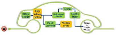
- A device that increases or decreases the voltage (AC or DC) of a power source depending on application. A converter that increases voltage is called a step-up converter and a converter that decreases voltage is called a step-down converter.
- In EVs/HEVs step-up and step-down converters are combined into one unit. An application of a step-up converter is converting EV/HEV battery voltage (typically 180-300 volts) to about 650 volts to power the traction motor.
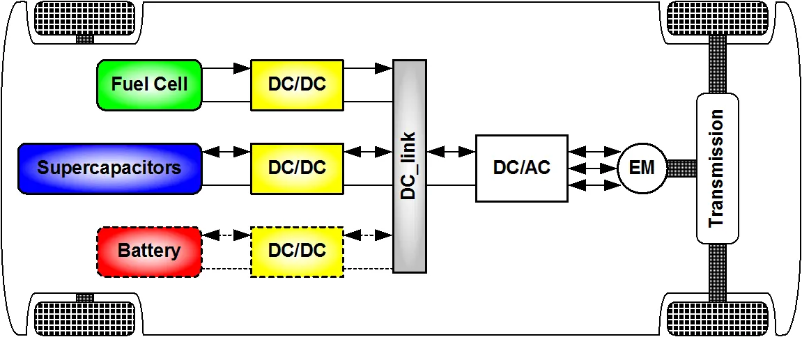
- The different configurations of EV power supply show that at least one DC/DC converter is necessary to interface the FC, the Battery or the Supercapacitors module to the DC-link.
- Non isolated converters:-
The non-isolated converters type is generally used where the voltage needs to be stepped up or down by a relatively small ratio (less than 4:1). And when there is no problem with the output and input having no dielectric isolation.
- There are five main types of converter in this non-isolated group:-
- buck converters
- boost converters
- buck-boost converters
- Cuk converters
- charge-pump converters
Reference
- https://www.intechopen.com/books/electric-vehicles-modelling-and-simulations/dc-dc-converters-for-electric-vehicles
- https://www.google.com/search?q=which+type+of+power+convertes+to+be+used+in+EV+and+HEV&sxsrf=ALeKk02aYmGZNWtabnGmYZ9UUi_cK19vfA:1625920736191&source=lnms&tbm=isch&sa=X&ved=2ahUKEwie5abfwtjxAhUO7XMBHWgcBRwQ_AUoAXoECAEQAw&biw=1366&bih=657
- https://allabouteng.com/types-of-power-electronics-circuits-converters/
2. An Electric Vehicle's powertrain with 72V battery pack in shown in the diagram below. The duty ratio for acceleration operation is 'd1' and for the braking operation the duty ratio is 'd2'.
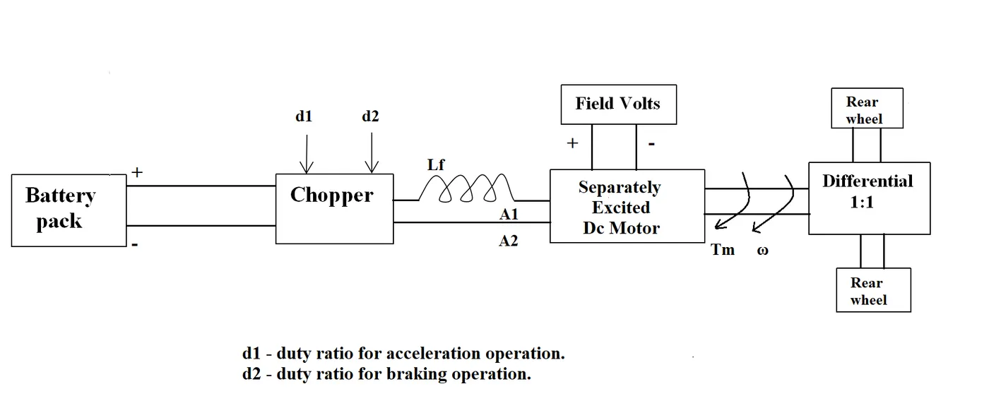
The other parameters of the electric vehicle is given below,
Motor and Controller Parameters:
Rated Armature voltage= 72 V
Rated armature current= 400 A
Ra= 0.5Ω, KΦ= 0.7 Volt second
Chopper Switching frequency= 400 Hz
The vehicle speed-torque characteristics are given by the below equation

What is EV steady state speed if duty cycle is 70%?
Given data:-
Battery pack = 72V
Duty ratio(acceleration) = d1
Duty ratio(braking operation) = d2
Armature voltage (Va) = 72v
Armature current (Ia) = 400A
Armature resistance (Ra) = 0.5`Omega`
DC machine constant(K`phi`) = 0.4Volt Second
Chopper switching Frequency (Fcs)= 400Hz
Duty cycle = 70%`omega`
Solution :-
Total output voltage of vehicle :
Vo = (battery voltage*duty cycle)/100
Vo = (72*70)/100
Vo = 50.4V
Vehical Torque euation is given as
`Tv=frac{Vv*kphi}{Ra}-frac{omega*(Kphi)^2}{Ra}`
`:. Tv=frac{(Vv-omega*kphi)*kphi}{Ra}`
where,
`Tv=`Vehicle Torque (Nm)
`Vv=`vehicle Voltage (Volts)
`omega=`Speed of vehicle (RPM)
`kphi=`Machine constant
`Ra=`Armature resistance
Substituting value in Equation ,we get
`Tv=frac{(50.04-0.7omega)*0.7}{0.5`
`Tv=`70.056-0.98`omega` (1)
`Tv=`24.7+(0.0051)`omega^2` (2) ..........Given Equation
By solving both equation
`70.056-0.98omega=24.7+0.0051omega^2`
we get quadratic equation as follow
`0.0051omega^2+0.98omega-45.356=0`
So by solving quadratic equation
`omega=`-230.7 and `omega=`38.54
As speed always be possitive considering positive value
`omega =`38.54 rad/sec
3. Develop a mathematical model of a DC Motor for the below equation using Simulink. ω">ω= V/Kϕ">ϕ-Ra/Kϕ">ϕ^2 .T
Solution in attachment.
4. Refer to the blog on below topic:
Induction Versus DC brushless motors by Wally Rippel, Tesla
Explain in brief about author’s perspective.
- Auther introduce the person who invented the electrical vehicle, In 1968,a Caltech undergraduate student, he built an electric car and won the Great Transcontinental Electric Car Race against MIT.
- He also write about evolution in using components in electric vehicle like, lead acid batteries, DC brush motors, and contactor controllers are replaced with lithium and DC by DC brushless or Induction.
- He introduce the function and difference between DC bushed and DC brushless motor.
- Author says that, DC brushless and induction drives use motors having similar stators the only differences are with control code.
- Inverter and motor currents are maintained at their lowest possible values. This minimizes the I² R (current² resistance) losses and thereby optimizes efficiency.
- Induction machines have no magnets,this means that at light loads the inverter can reduce voltage such that magnetic losses are reduced and efficiency is maximized.
- Permanent magnet (PM) rotors are also difficult to handle due to very large forces that come into play when anything ferromagnetic gets close to them.
- The author wants to state that induction machines are more difficult to control. The control laws are more complex and difficult to understand. Achieving stability over the entire torque-speed range and over temperature is more difficult with induction than with DC brushless. This means added development costs, but likely little or no recurring costs.
- Lastly author wants to say about moving forword for electric vehicles that, so much of the hardware is common for both drives could mean that we will see induction and DC brushless live and work side by side during the coming golden era of hybrid and electric vehicles.