Week - 4
OBJECTIVE:-
1. Implement control logic of a “washing machine” using Stateflow.
CONDITIONS:-
- If the power supply is available, the system gets activated.
- If the Water supply is not available, stop the process & indicate through LED.
- Soaking time should be 200s followed by Washing time of 100s.
- Then rinsing happens for next 20s & dryer runs for 50s.
- After all the processes have completed turn on the finished LED.
2. Make a Simulink chart for the “Gear shift” logic as per below conditions:
Speed Range(kmph) Gear
0 to 15 1
16 to 25 2
26 to 40 3
41 to 60 4
Above 61 5
Give speed input while the simulation is running & display the gear number.
- Implement control logic of a “washing machine” using Stateflow
SIMULINK MODEL:-
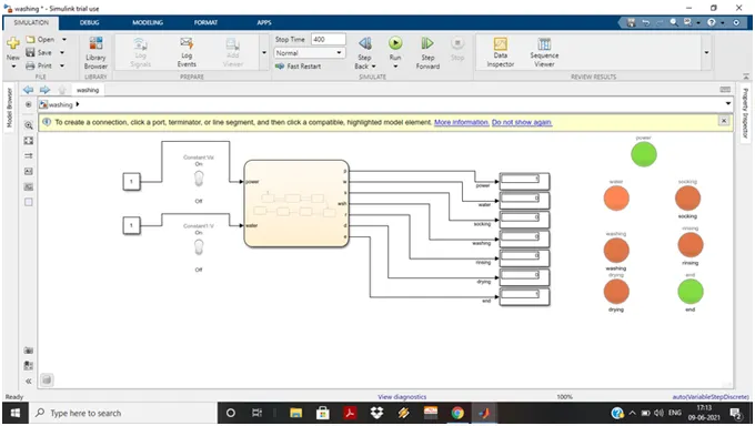
- This simulink model is constructed with 2 constant blocks for input to a washing machine as power supply and water supply.
- the toggle switch is also connected for better understanding of ON and OFF condition of washing machine.
- For out put 7 number of digital display are connected along with 7 LED lamps.
- LED lamps shows the indication for on going process.
- For input "1" LED shows "GREEN" indication.
- For input "0" LED shows "RED" indication.
For constructing the given conditions CHART block from stateflow is used. Construction as follow.
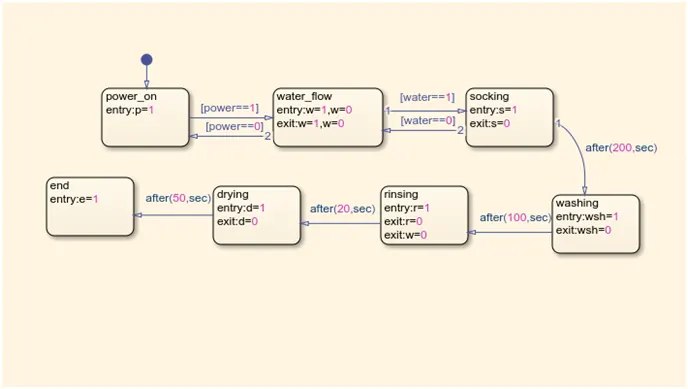
- Inputs:- Power on(p),Water flow(w).
- Outputs:- Socking(s), Washing(wsh), Rinsing(r), Drying(d) and End process(e).
- Here we have some cases to build:-
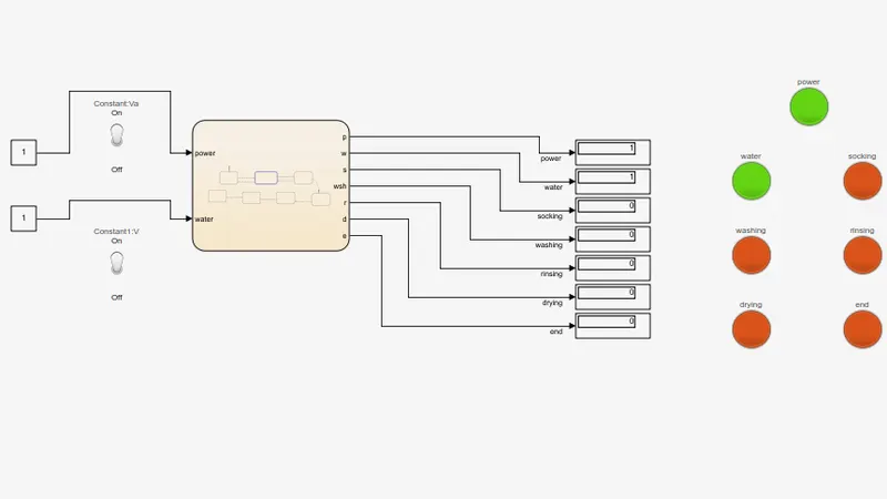
a. If the power supply is available, the system gets activated.
For this we need to put “1” in 1st constant block, that means the toggle switch is turn ON. The power is start flowing through the system. The process indication is shown by the LED lamp.And process further proceed to water flow of system which is the another input of the system. As water supply is ON the process continues to next level.
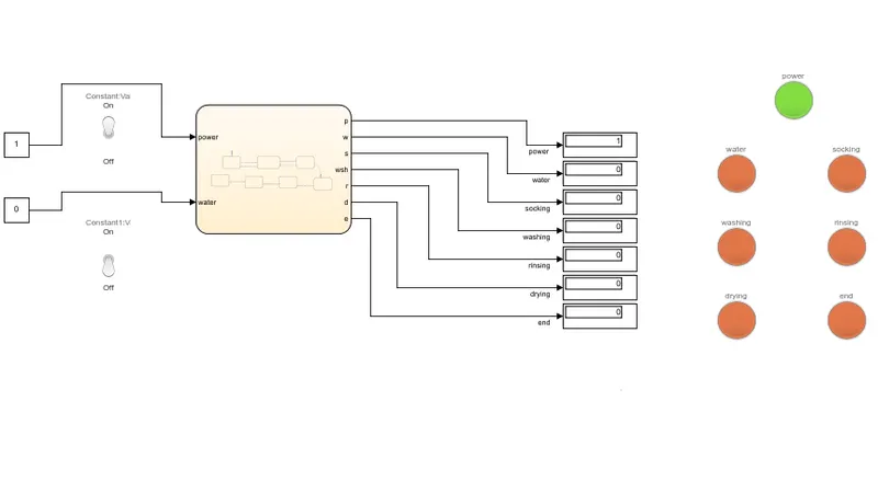
b. If the Water supply is not available, stop the process & indicate through LED.
As power supply is ON the washing machine moves towards the water supply and by taking input from water supply it process futher, but if the water supply is OFF washing machine stops the futher process and LED 'RED' light displays at output.
c. Soaking time should be 200s followed by Washing time of 100s.
As power=1,water=1 the process shifts towards the socking state. The socking state work up to 200sec and continues washing state for 100sec.
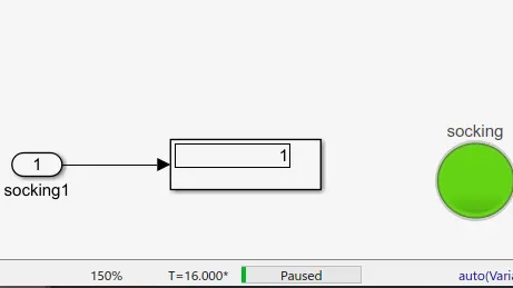
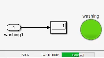
After the socking state, washing started after 200s, it is completed after 100sec as shown bellow
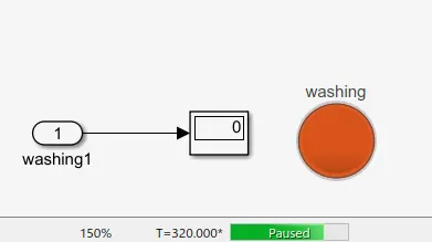
d. Then rinsing happens for next 20s & dryer runs for 50s
After washing procees move onward to rinsing state for 20sec.
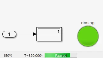
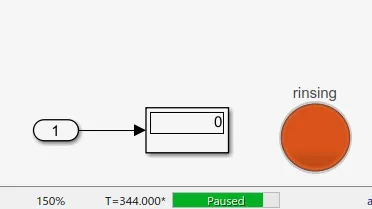
After finish with rinsing the dyring process is starts for 10 sec.
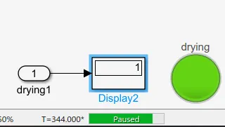
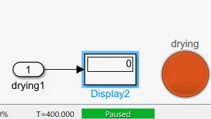
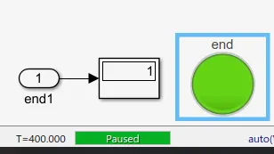
e. After all the processes have completed turn on the finished LED.
After the dying process the washing machine finish all the process of washing cloths,so it is a end of the program and it is shown by the LED indication. as follow:
CONCLUSION (RESULT):-
By using stateflow we can build the any electronic working function by giving proper commands. We can easily apply the time delay. It is a more easier way to understand system.
2. Make a Simulink chart for the “Gear shift” logic as per below conditions:
Speed Range(kmph) Gear
0 to 15 1
16 to 25 2
26 to 40 3
41 to 60 4
Above 61 5
Give speed input while the simulation is running & display the gear number.
SIMULINK MODEL:-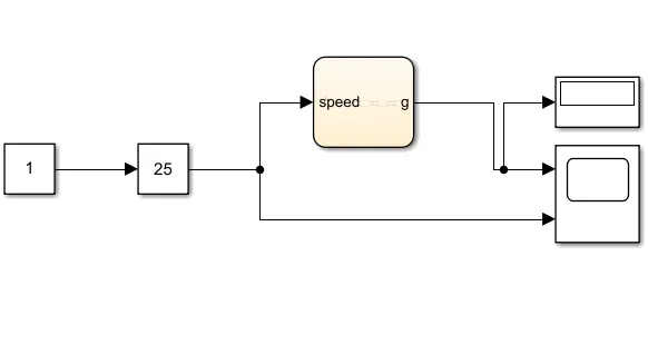
This simulink model contain CONSTANT and SLIDER GAIN block as an input. And scope and digital display as out put. Slider gain block used to develop different values for gear.Stateflow used to build all the conditions by using CHART block. In this block we can build the all the condition by providing proper input and output data. In this simulation we have multiple inputs by slider gain and single output in 2 forms as digital display and scope.
CHART
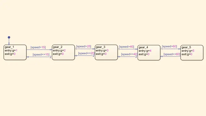
For this chart input is given as speed and it works on gear conditions given. As per given information we need to construct speed range for each gear number simultaneously. For gear 1 the speed limit is 0 to 15, As gear changes to 2 the speed limit will be 16 to 25, For 3rd gear the speed limit is 26 to 40, For 4th gear it is 41 to 60 and last 5th gear above 61 speed is required. After constructing these in chart block output is obtained at display and scope. Where the display shows the number of gear at perticular speed.
considering some value for result:
GEAR : 1 2 3 4 5
SPEED LIMIT : 10 20 30 50 70
As we change speed value in input the value of output changes accordingly.
GEAR 1 : SPEED 10
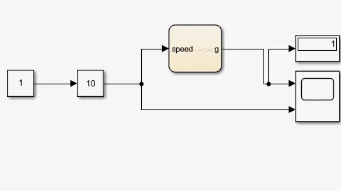
GEAR 2 : SPEED 20
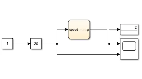
GEAR 3 : SPEED 30
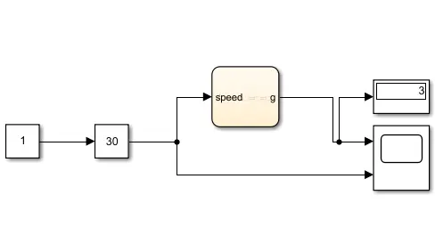
GEAR 4 : SPEED 50
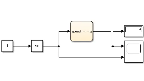
GEAR 5 : SPEED 70
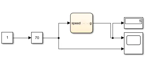
SCOPE OUTPUT:
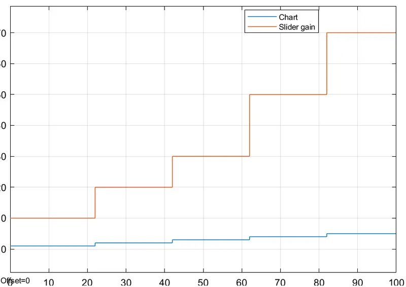
From above we are able to see each number of gear in one frem.
CONCLUSION:-
By this simulink model we studied the putting different values in one chart block with different speed range.