Week 6 - Creating connection for Rear door
Aim: To Prepare Given FE model for Connections using NASTRAN DECK-ANSA V20.14
Connections Procedure Includes :
1.Assign Different PID's for Given FE Door Model
Before PID's Assign:
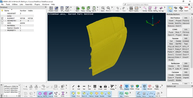
After PID's Assigned:
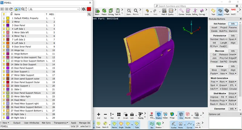
2.Connection Of Bolted Regions:
Connection between Hinges and Door Area
a-Create 3D Point Using ONCog Tool by selecting Edges of Middle PID hole region
Tool Location:TOPO Deck->Points->OnCog
b-Now Convert 3D Point into Bolt using Convert Option
Procedure Includes:Convert->3D Point->Select Point by Left Mouse Click(LMC)->Confirm
c- Now to Deploy Connection of bolt i use Connection Option
Procedure Includes:Connection->Select Bolt Point->Confirm->Assign PID 1,2&3 for connections->FE Rep Type-BOLT->provide required values ->Apply->Realize
Bolt Connection Tab Overview:
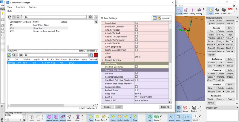
d-Connection of BOLT is Deployed Mentioned Below:
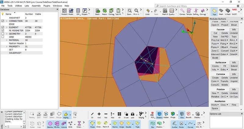
e-Repeat same process for Remaining Bolted Regions
3.Connection Between Hinge and Car Body:
-First Deploy Connecion for free holes using RBE2-Many Nodes Option
-Now Deploy 2Node Cluster Using RBE2-Two nodes option w.r.t 5Degree of Freedom because there should be a free rotional z-axis to open the door
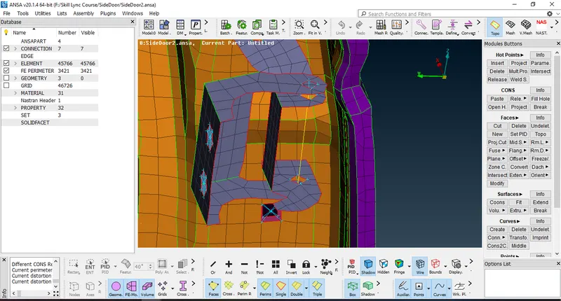
-Repeat process for other Regions
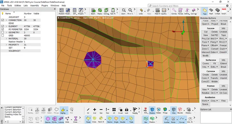
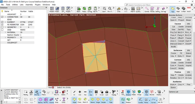
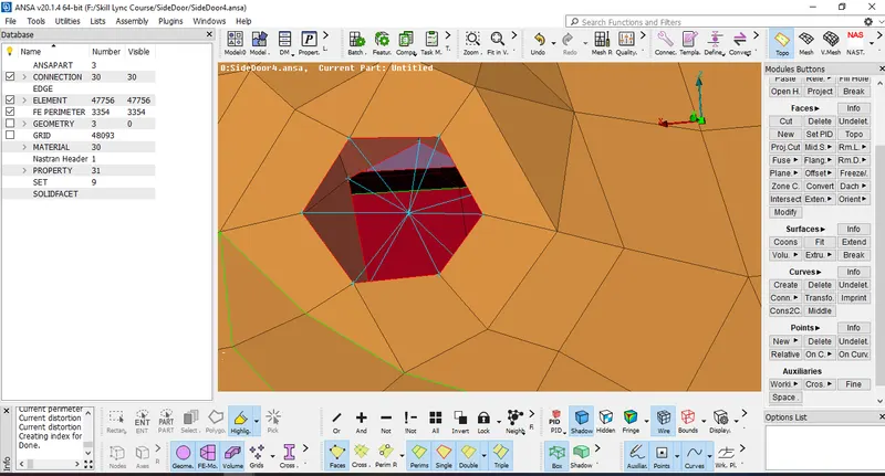
4.Connection of Two Holes using RBE2 Cluster-many Nodes:
-To Deploy connection of Holes between two faces i use RBE2 Cluster-many Nodes Option
Location of Tool-NASTRAN DECK->ELEMENTS->RBE2-many node ->select elements ->Confirm
some of the Screenshots of RBE2-many node Connections are Mentioned below
5.Connection of Faces using RBE2 Cluster-many Nodes:
-Every Body Should be Connected properly before going for simulation
-when a body is having Geometrical errors and it doesn't have holes to give connection with other face it should be connected using FE Elements
-Procedure Includes
***select RBE2-many nodes option and select FE Elements of Both Faces and Confirm
-After RBE2 Element connection mentioned below
6.Spot Weld Connection:
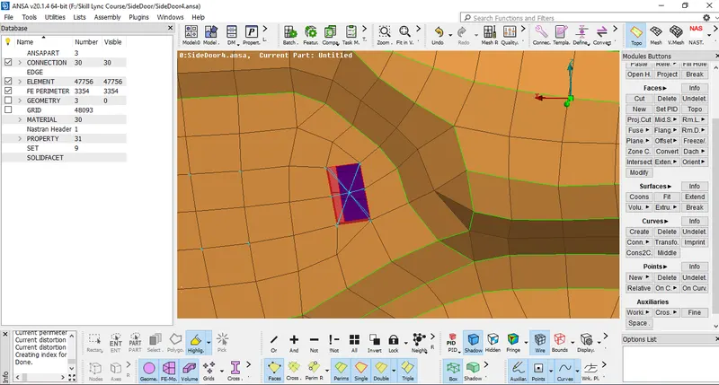
-Creat 3D Point by using ONCog Option in between Elements where spot weld is needed
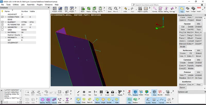
-Convert 3D Point to Spot Weld Using Convert Option
**Convert->3D Point->Select Point by LMC->Confirm
-Now To make Connection
**Connection Option->Assign PID's->Select RBE3-HEXA-RBE3 in FE rep type->Enter Search Dist->Assign PSOLID ID(Create If needed)->Apply->Analyze
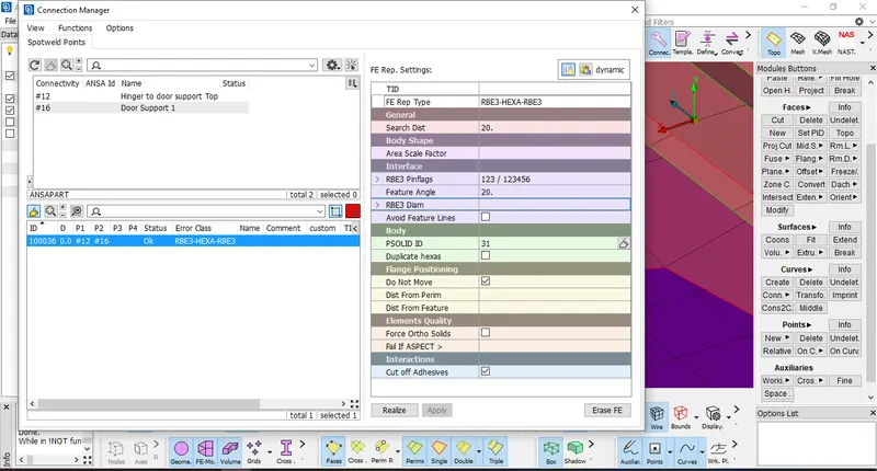
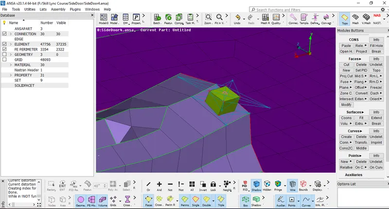
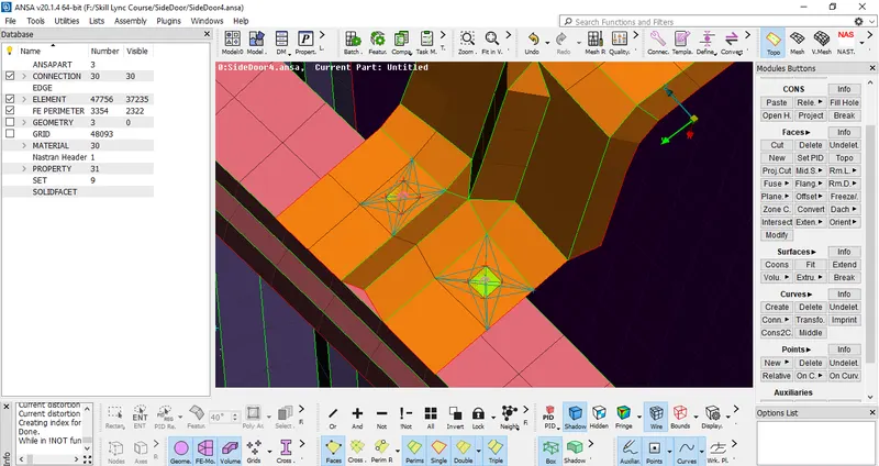
Result Mentioned Below
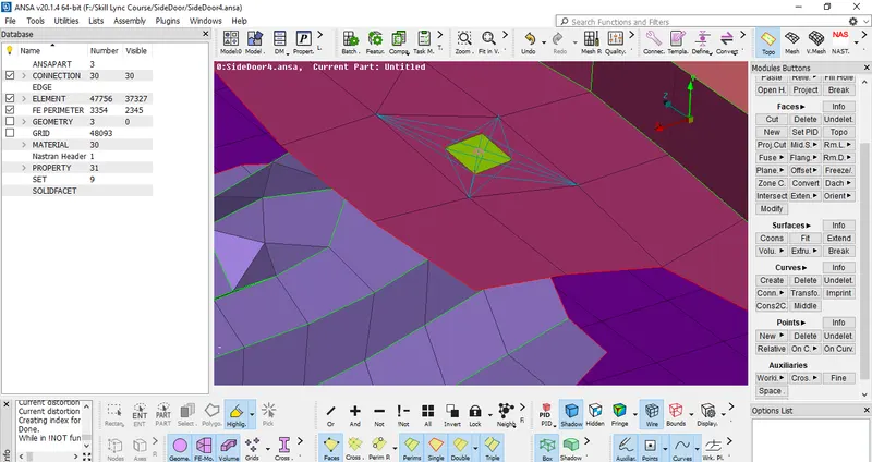
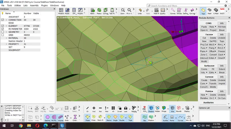
-An Hexa will be Created like that to Represent that it is Spot Weld
-Repeat the process for the remaining areas if required
7.CBUSH Connection in Mirror Region:
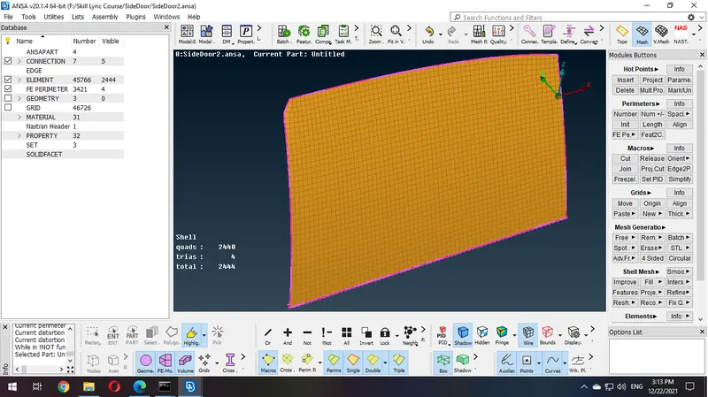
-To Deploy Cbush Connections First Create Curve of Edges by using Feat2Curve Option
Tool Location-Mesh Deck->Perimeters->Feat2Curve->Select Edges->Confirm
-Convert this Curve into Spot Line Using Convert->Curves->Select Curve->Confirm
-This Connection should be on Both side Because Mirror is Fixed from all areas
-To Ensure Proper connection of mirror on both sides i use transform(copy) the spot line curve with respect to y-axis at distance of 10
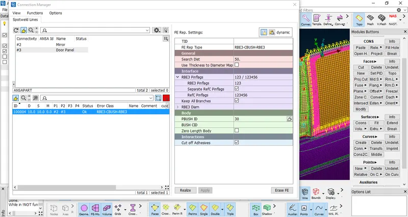
-Now to create Cbush Connection select connection option ->select spot line->confirm---a connection tab will be pop up
-Now Give Distance value of 10 and assign 2PID's and select RBE3-CBUSH-RBE3 option in FE rep type->Give Search Distance of 50 -> check "Keep all Branches option"
->Assign PSOLID PID->Apply ->Realize
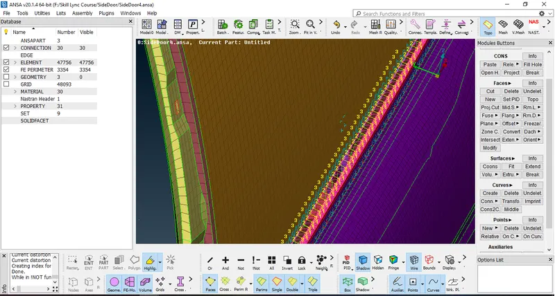
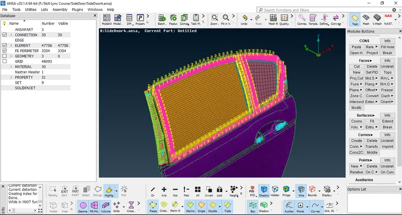
Results are Mentioned Below
8.Connection of Door Handle:
-Create RBE2 Cluster using RBE2 Many Nodes on Door Handle Connections
-Create 2node RBE2 Cluster between connections
-one point will be auto created in between two node connections
-now we need to assign The Mass on Handle Region
-To Assign Mass Click on INFO tab Located at NASTRAN->ELEMENTS->INFO
-A CONM2 Tab will popup Mentioned Below
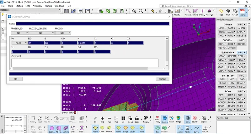
-Assign Value of Mass(Should be in Tonne)
9.Save .ANSA File
Learning OutComes:
-Learned How to Prepare Model For Simulation by Providing Different Connections at Different Areas.
Conclusion:
After Completion of This Challange I can Perform Connections to any Complex Model.