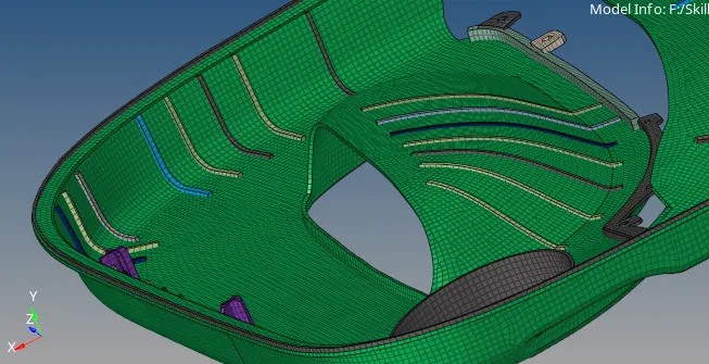
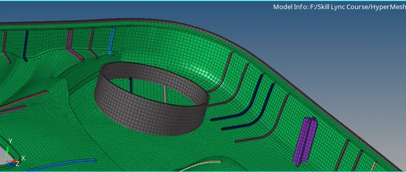
Week 12:Project-1-Meshing of Door Inner Panel Challenge
AIM:
To Generate Manual MidSurface, Deploy Mesh on Generated MidSurface, Assign Thickness & Run Required Quality Checks on Door Inner Panel.
Procedure:
- opening .stp file
- Cleaning Up Geometry
- Creating Mid-Surfaces with Fully Manual Method
- Assigning Properties w.r.t Thickness of Different Parts
- Giving Quality Criteria
- Generating Mesh
- Improving Quality of Mesh
- Perform Quality Check
1- Opening .stp file:
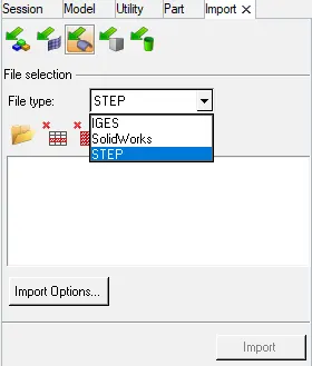
- Given File is in .stp Format
- Select STEP from list and select model
- click on import
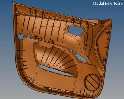
- Different Views of Model
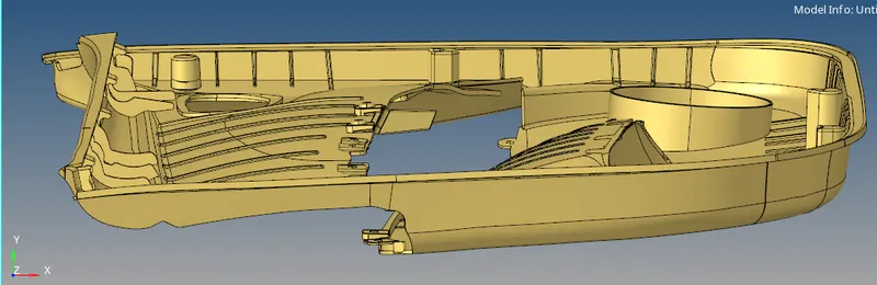
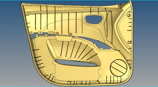
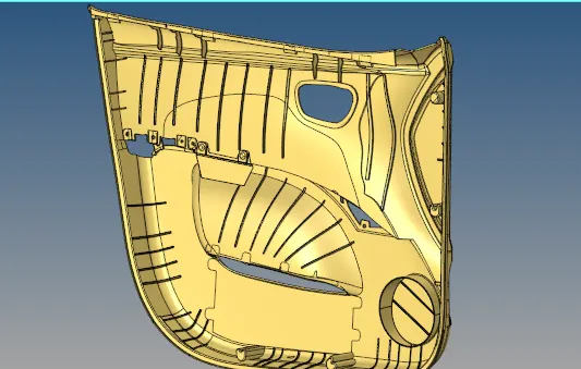
- Here i have changed the color of component
2-Cleaning Up Geometry:-
- At some areas in Geometry we need to fix free edges
- some of the areas are mentioned below
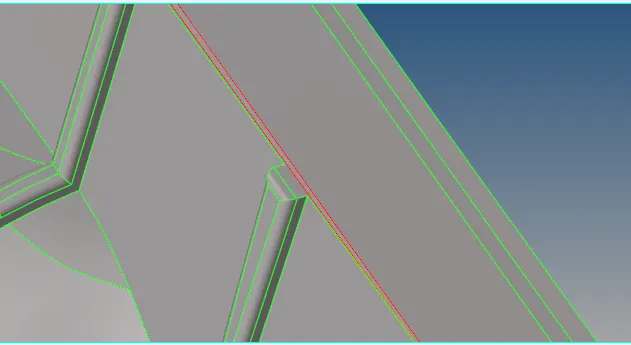
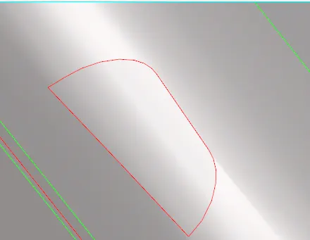
- we can fix this kind of free edges using different tools like
- 1-Geom->Surfaces->Ruled
- 2-Geom->Quick Edit->Replace
- 3-2D->Spline->Surface only
- Here i have fixed free edges using tool Geom ->Surfaces->Ruled
3-Creating Mid-Surfaces with Fully Manual Method:-
- Given Geometry is Plastic Part so it has irregular shapes and Surfaces.So, hypermesh is not able to generate MidSurface Using AutoMid Tool
- So, i use to Generate Mid Surface Using Fully Manual Method
- First i use to Measure thick of different areas of Given Model
- By Deploying Temp Node on one surface and projecting this nodes on other surface we can accurately measure thickness of any parts
- Above Method is as follows
- First Deploy temp nodes randomly on either areas of given Model using Tool Geom->Temp Nodes-> Hold Left Mouse Button on surface and Click on add to Deploy Nodes

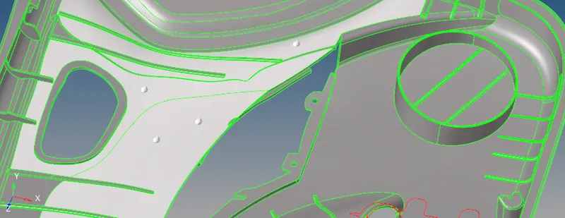
- Now Using Project Tool we can duplicate this nodes and project on other side
- go to Tool->Project->To Surface Select Nodes and right mouse click on nodes and duplicate them


- now select surface on which we want our Nodes to be projected
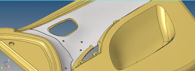
- Along Vector should be Suface Normal

- Now click on Project
- Now By using Tool Geom->Distance->two Nodes Tool we can measure thickness of Given Model
- for Better Visualization i have converted the Geometry from shaded mode to wireframe mode and measure the thickness
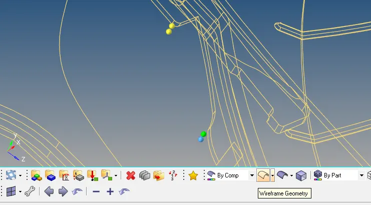

- here thickness of given model is 2.8mm
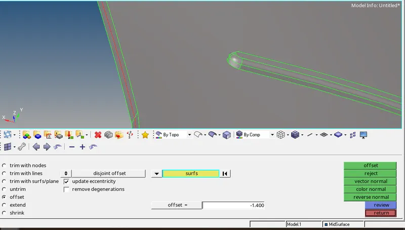
- now i use Geom->Surface Edit->Offset Tool to offset the surface
- Before Offseting create a new Component name as MidSurface and make this component as current component
- by selecting the surface which doesn't have free edges and checking vector direction give offset value and duplicate the surface with current component
- Now click on offset
- Our MidSurface has been Generated succesfully
- To Generate MidSurface for this kind of Rib Like Areas i use to follow this Method
- Method to generate MidSurface for Rib Like Areas
- a-Create new component named as Lines and make this component as current component
- b-now using Tool Geom->Lines->MidLine create MidLines

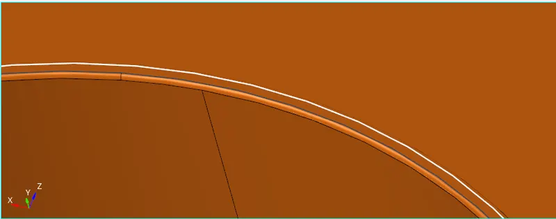
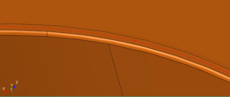
- Similarly Generate MidLines for Bottom area
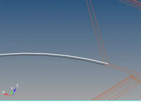
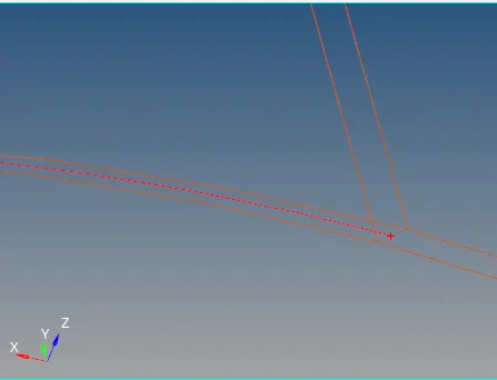
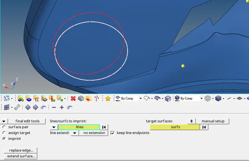
- now project this Bottom MidLine on MidSurface using Tool Geom->MidSurface->Final Edit Tool->Imprint


- select line from line/surf to Imprint Option and select line extend to no extension

- Select target surfaces to manual setup
- now click on lines and select target surfaces
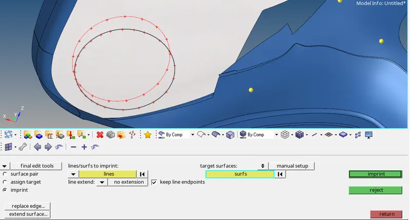
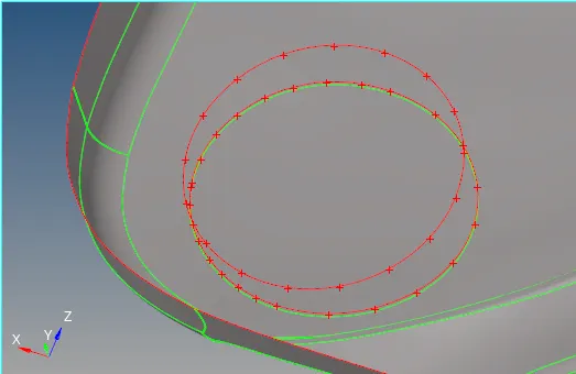
- Now Click on Imprint
- Below mentioned image shows line imprinted on selected surface succesfuly
- now by using Different Tools we can create new Surface
- Tool to create Missurface are
- 1-Geom->Surfaces->Ruled
- 2-Geom->Quick Edit->Replace
- 3-2D->Spline->Surface only
- After Generated MidSurface for this rib area
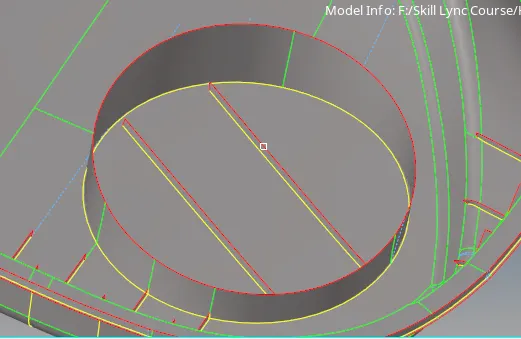
- Similarly generate MidSurface for Other Rib like Areas
- Some of the Images of ribs after generating Mid Surface
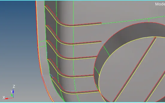
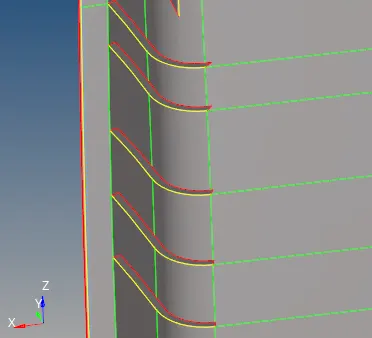
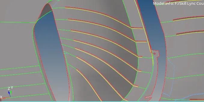
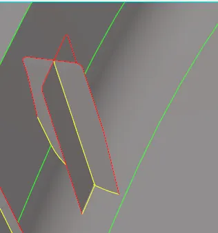
- For This Kind of Dock Like areas
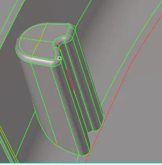
- Generated MidSurface like Mentioned below
4-Assigning Properties w.r.t Thickness of Different Parts:
- Before assigning property to any component, first we need to Measure thickness of Different areas of Given Model
- now use Tool Geom->Distance->two points/two nodes->select two points/nodes to calculate thickness of any part
- use above mentioned method to measure thickness of different areas of model
- now create new component w.r.t to their thickness
- Now Right Mouse Click on Menu tab to create new component
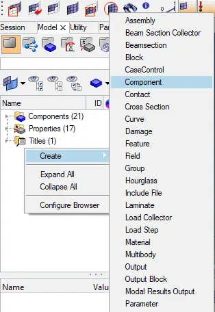
- and name them w.r.t their thickness for better understanding
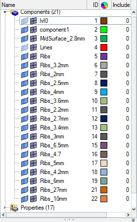
- Similarly create new property cards by Right Mouse Click on Menu tab
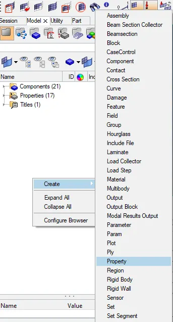
- and name them w.r.t their thickness for better understanding
- now click on property and assign thickness value in Below tab "T" area
-
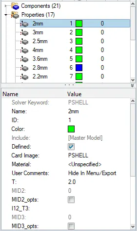
- For varying thickness ribs assign average thickness
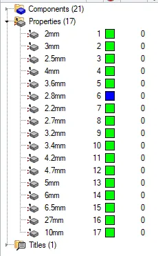
- Some of the properties are mentioned below with their assigned thickness
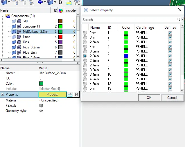
- Now assign The same property to component
- To Assign Property select Component
- New Tab will PopUp in Status Bar Area
- click on property and select property from property Tab
- Below Image can refer
- Repeat same process for remaining parts
5-Giving Quality Criteria:-
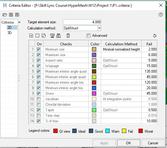
- Now before going for meshing we need to give some Quality criteria to HyperMesh
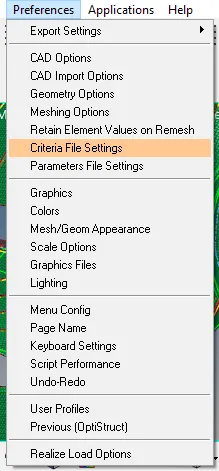
- To apply Quality Criteria go to Title bar->Preferences->Criteria File Settings
- Enter Required values and save the Criteria file for future use
- click on apply
6&7-Generating Mesh & Improving Quality of Mesh:-
- Now to Generate Mesh consider only Mid-Surface
- Mesh should be generated on Mid-Surface
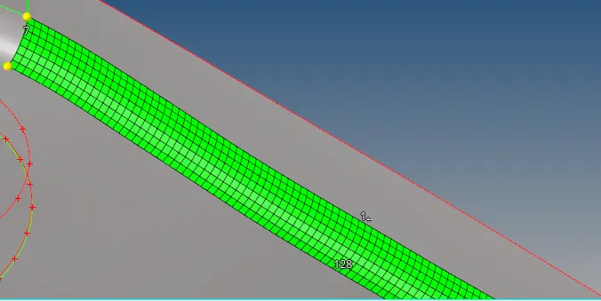
- To Mesh consider any area and use Tool 2D->AutoMesh



- Select surface and Click on Mesh
- Mesh will be Generated Shown Below
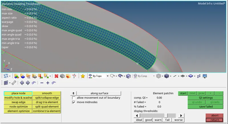
- To Improve Mesh Quality use tools
- a-2D->Quality Index->Cleanup Tools
- b-2D->Rebuild Mesh>Select Elements and click on Rebuild


- Our Mesh Should Pass all Quality and there should be no Failing Quality Elements
- Images of Given Model After mesh
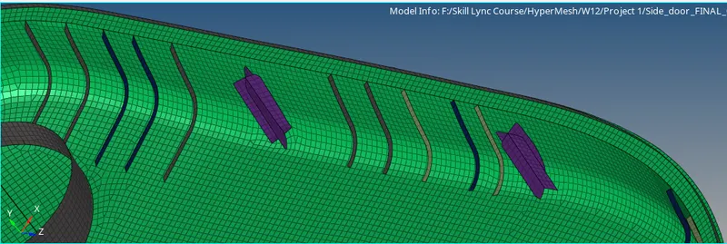
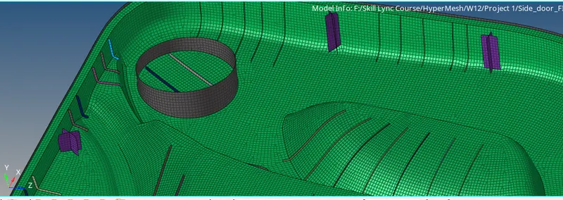
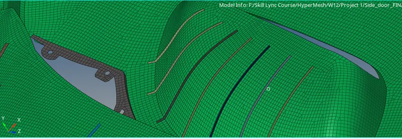
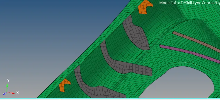
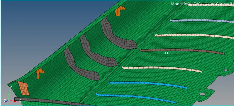
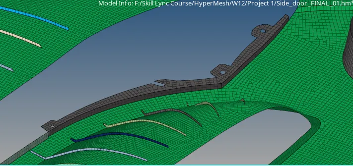
- Our Mesh Should have a proper flow avoid trias as much as possible
8-Perform Quality Checks:
- Check for free edges using tool
- Use Tool->Edges->find:Free Edges->Elements->all->Find Edges

- there should be no free edges in between elements
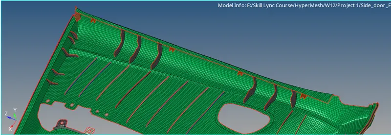
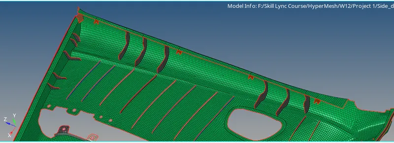
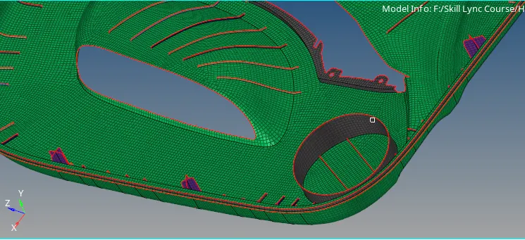
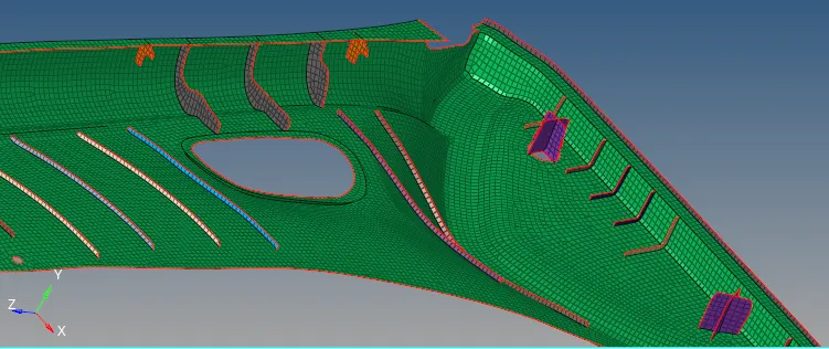
- Repeat same for remaining parts
b.Check for Normals:
- Use Tool
- Tool->Normals->Elems->Select all Elems->Display
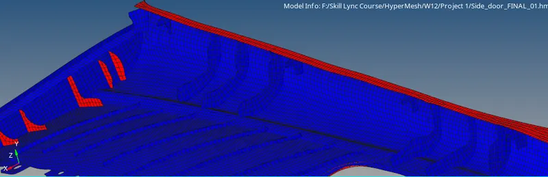
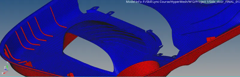
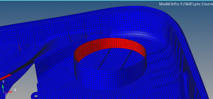
- all the elements on surface side should be in same color
- if some elements found different color on same plane select that elements and make them reverse
Learning Outcomes:
- Learned how to generate mid-surface with Different Manual Options
- Learned how to generate mesh on mid-surface
- Learned how to assign property with thickness to mid-surface and mesh
- Learned how to perform several checks on meshed parts
Time Taken to Complete This Challenge: 13 Hours
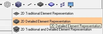
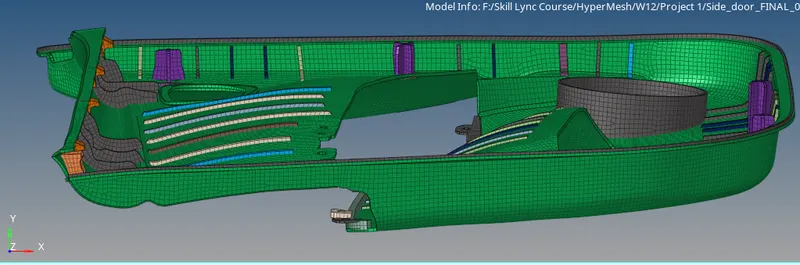
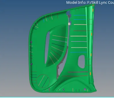
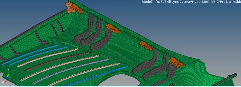
Final Model Images of Model in 2D detailed Element Representation:-