Week 6 - CHT Analysis on a Graphics card
Aim:
Perform a steady-state conjugate heat transfer analysis on a model of a graphics card. You can use appropriate materials of your choice for the simulation. Make sure to properly define the correct solid and fluid zones. Refer the video for further clarification and the model is provided below the video.
Run the simulation for best possible mesh with combination of coarse and refined mesh in different regions. Explain the reason for choosing the particular mesh settings.
Objectives:
- Run the simulation by varying the velocity from 1m/sec to 5m/sec for at least 3 velocities and discuss the results.
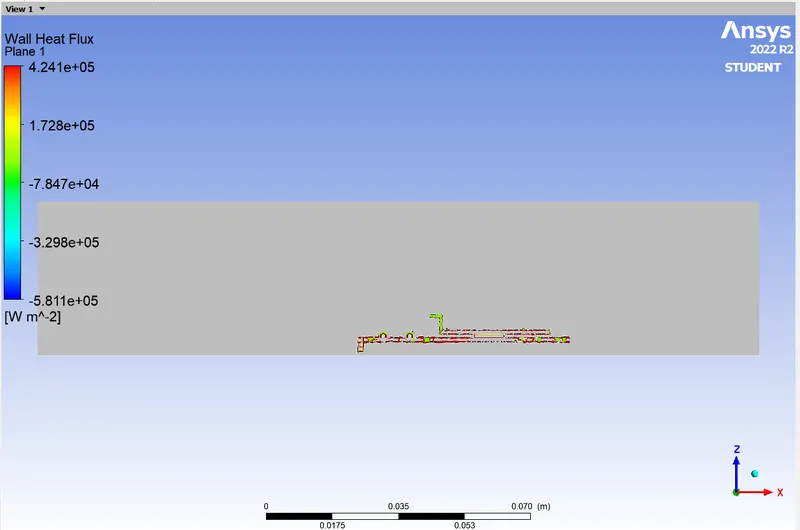
- Find out the maximum temperature and heat transfer coefficient attained by the processor.
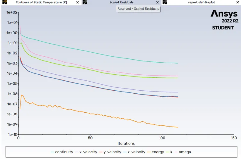
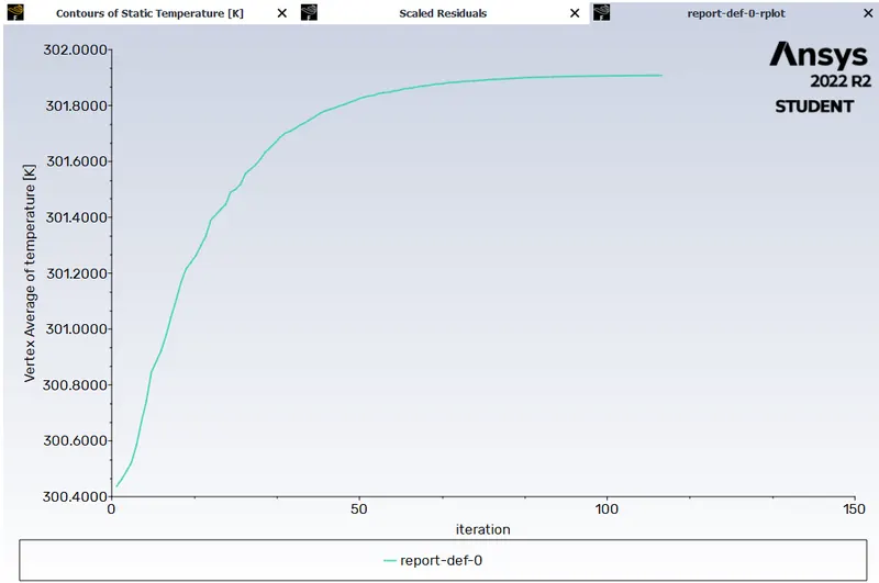
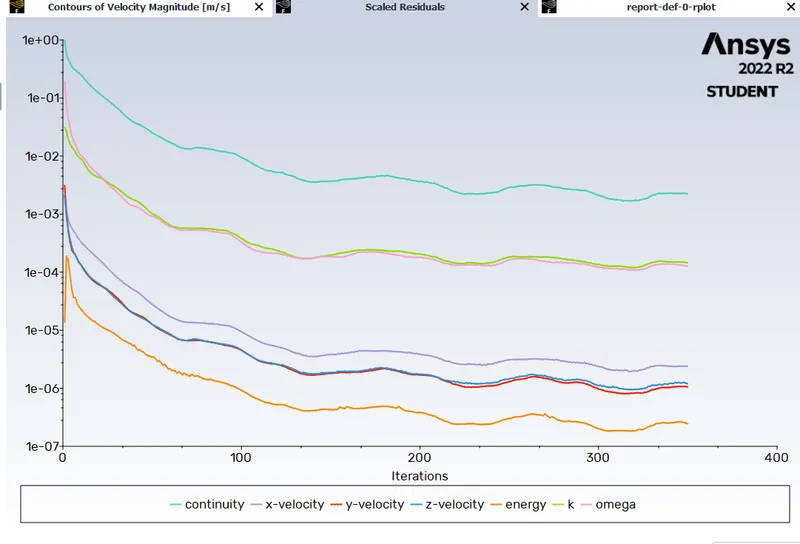
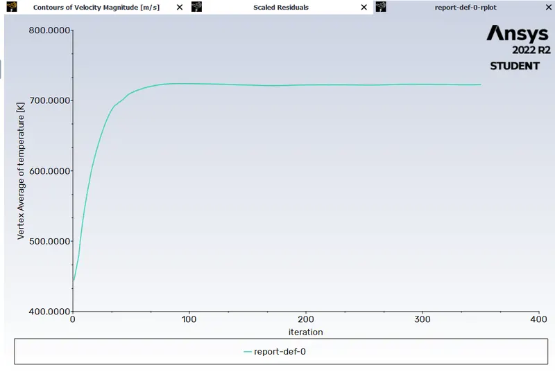
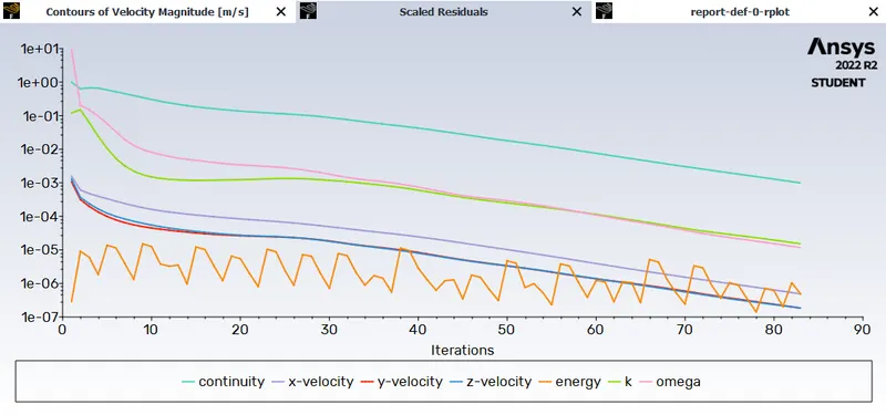
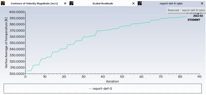
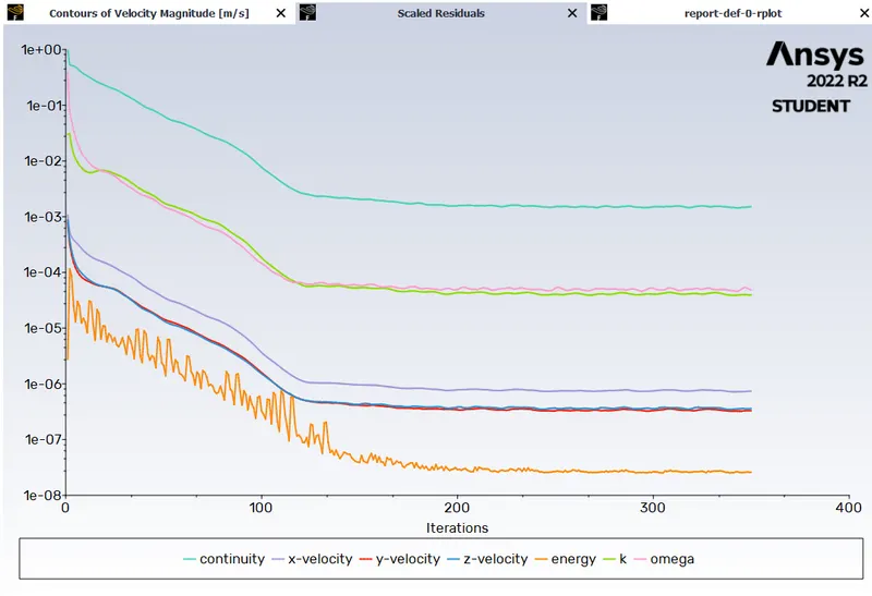
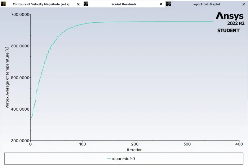
- Prove that the simulation has achieved convergence with appropriate images and plots.
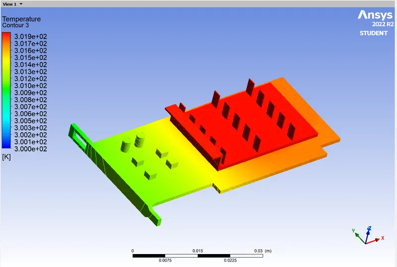
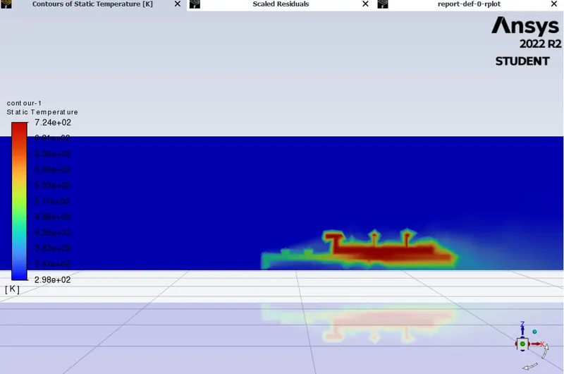
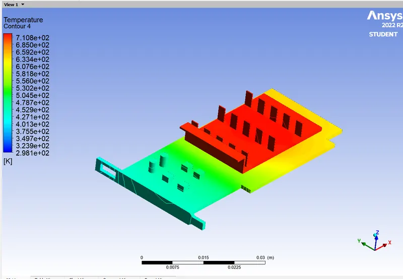
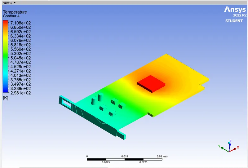
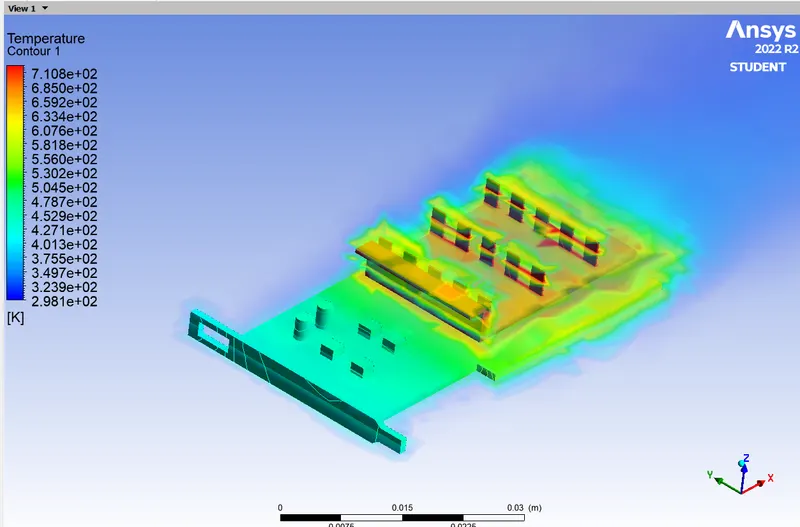
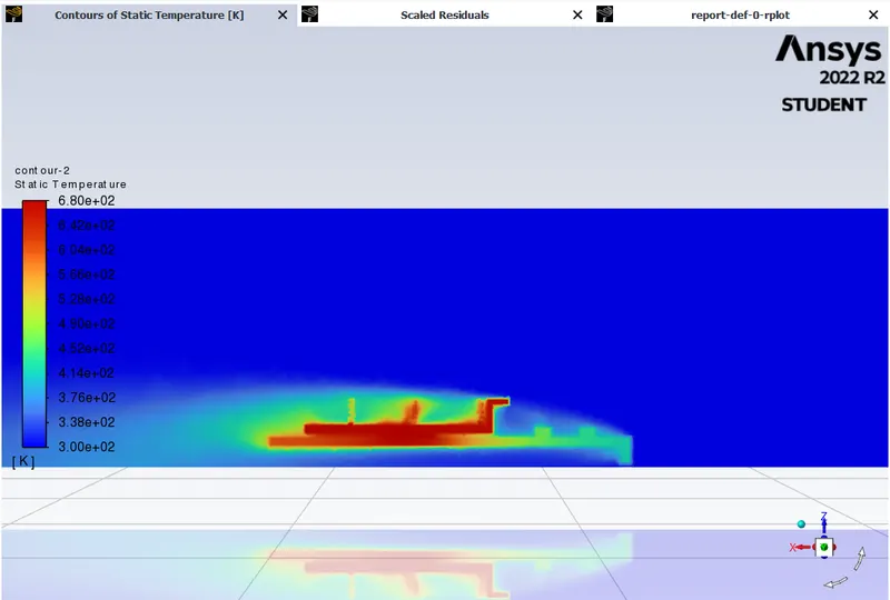
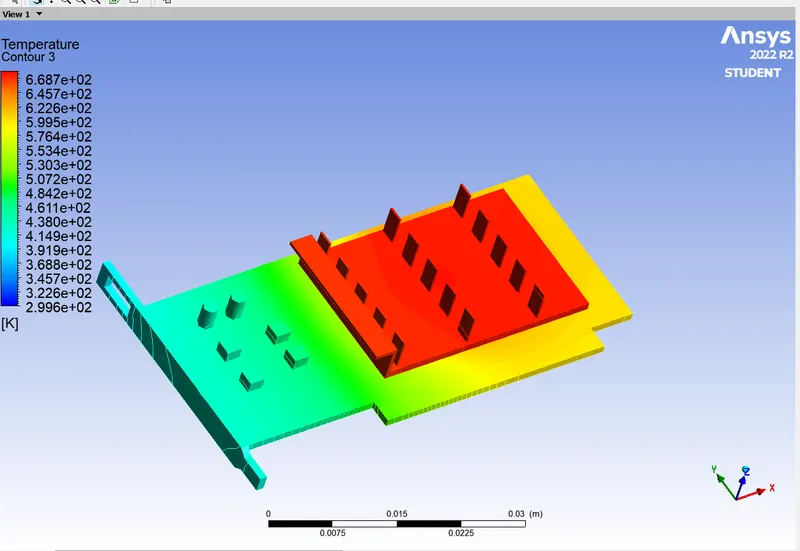
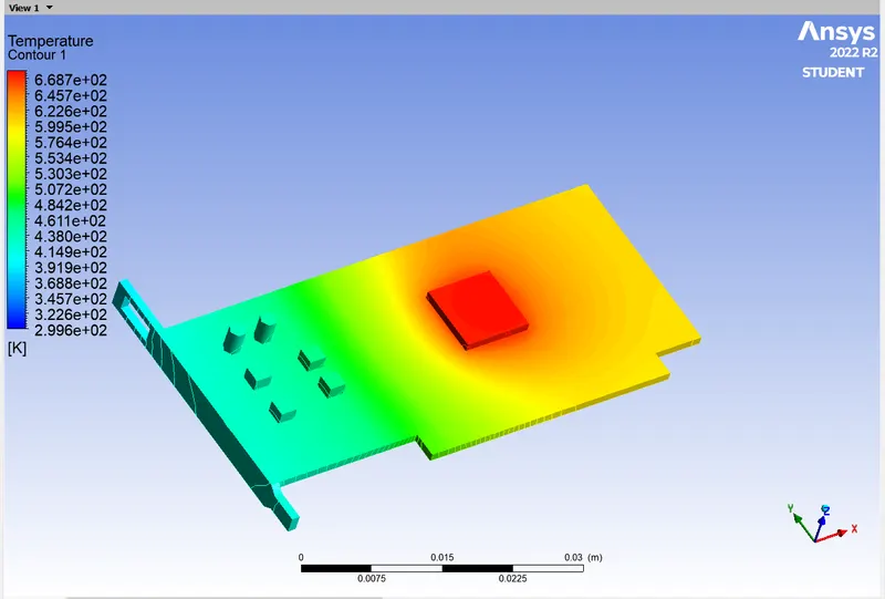
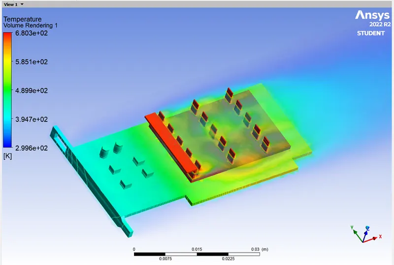
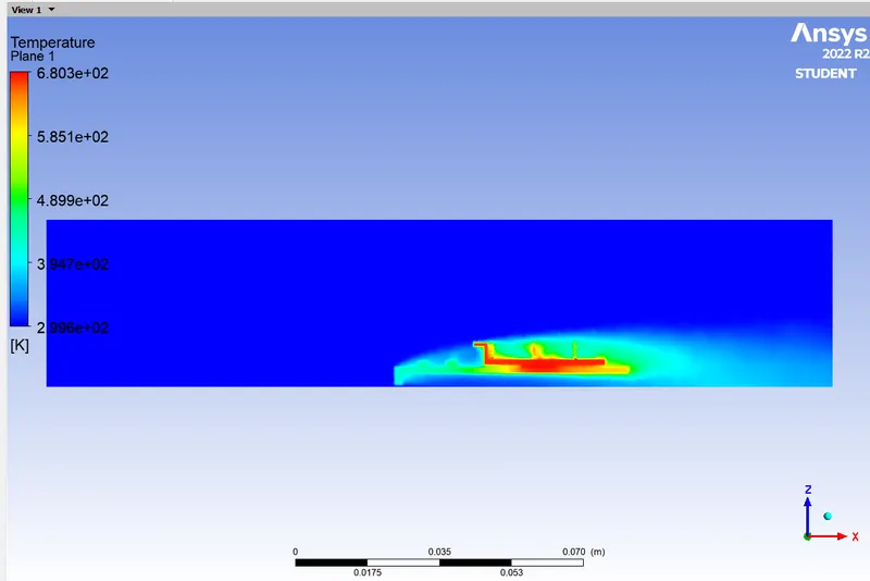
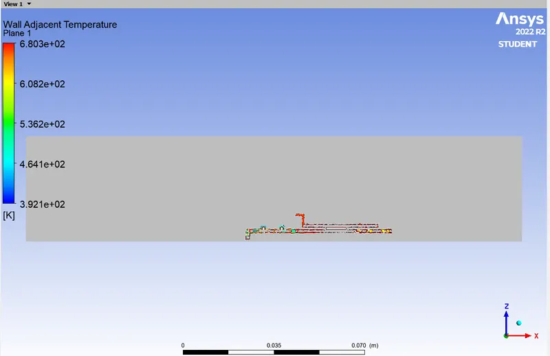
- Identify potential hotspots on the model.
Introduction:
Graphic Card or GPU is an electronic component often a computer's pepheral, responsible for computing the graphic signals, later transmitted to a graphic device. It has various range of performance as well as power usage. based on the design, the power rating is often specified on the package, the gpu may have a power rating of over 50W to 2000W. Many system architectures prefer modular gpu's for better power and accordingly heat management.
Outline study:
Conjugate heat transfer simulation has been done to achieve the objective. Since the study is of computational in nature, mesh refinement is a compulsory task. Mesh refinement strategy and study has been discussed in the next section. After mesh refinement the study has been followed up in two cases, as discussed below.
Case 1:
Inlet Velocity of 1 m/s is to be applied at the inlet boundary.
Since the velocity is the least among all the cases, less cooling is expected in this case. Heat transfer coefficient and maximum temperature has to be calculated in this case.
Case 2:
Inlet Velocity of 5m/s is to be applied at inlet boundary.
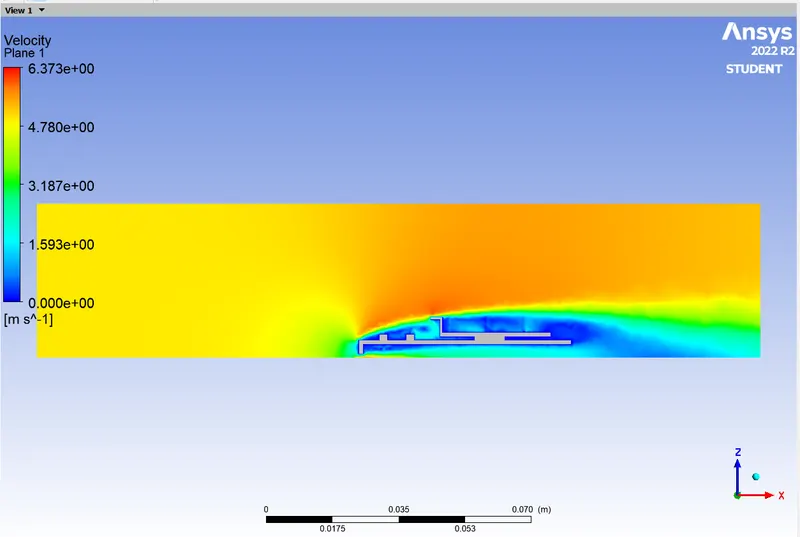
Since the velocity is increased further, the best performance among the three case is expected. Also, the velocity increase will lead to turbulent effect which can drastically affect the heat transfer. The best performance is expected in this case.
Geometry & Assumptions:
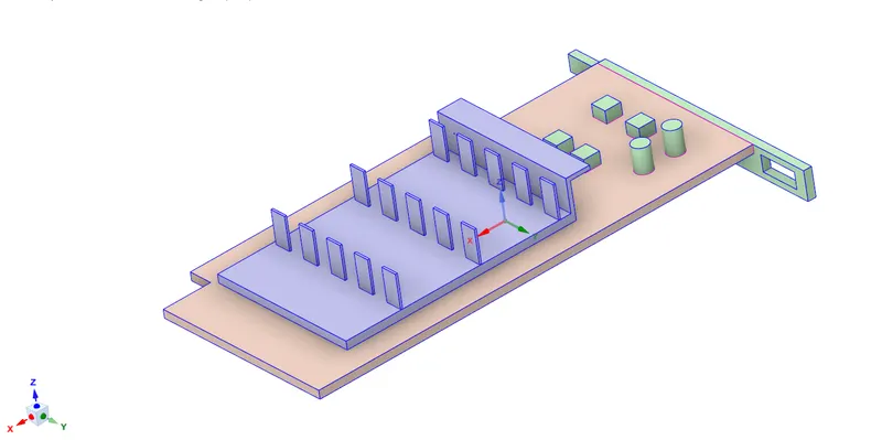
The geometry considered for the current study is a simplified model of the graphics card. The entire card can be classified into three major regions:
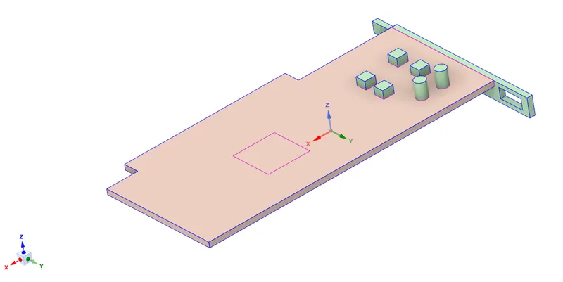
1) base of the card
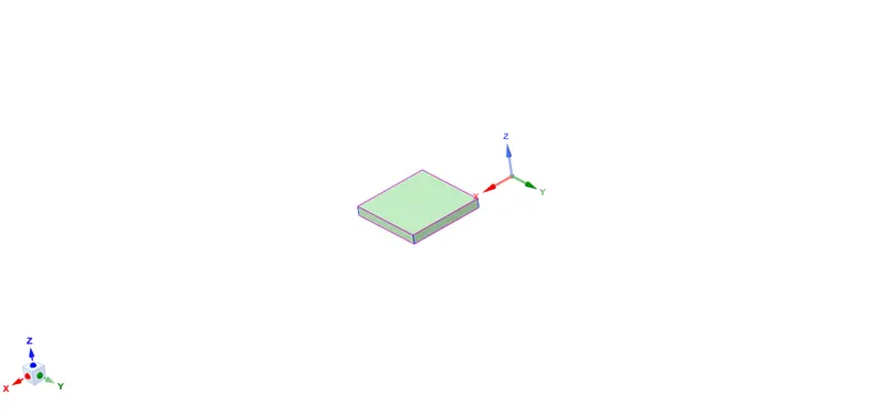
2) processor
3) fins
The base of the card includes everything on the card except the processor and cooling component fins. The base is made steel which is the most commonly used materials for designing PCB. The processor will act as the energy source because of the heat generated due to the supply of the electrical power and is assumed to be made of silicon (there is no silicon data in fluent database in my licence hence i have made silicon by giving data). The fins provide convective cooling to the processor so that there are no thermal damages on the graphics card. The fins are assumed to made of standard copper available in Fluent database.
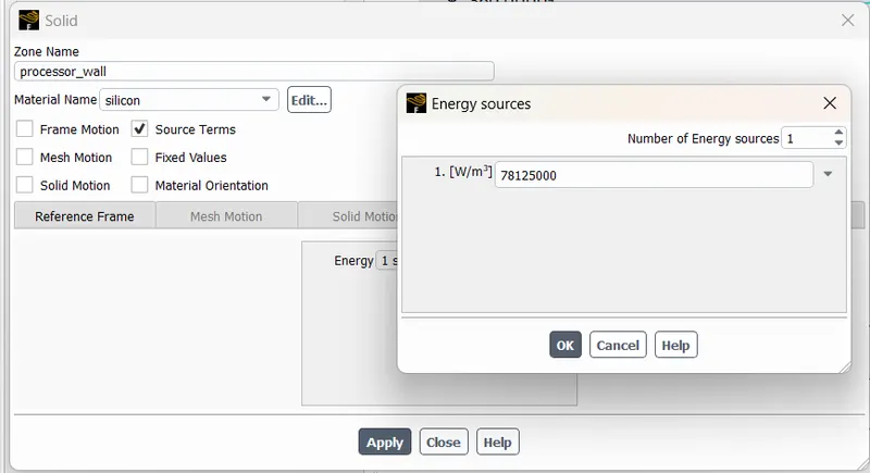
Here we are going to see a new term volumetric heat sourse. volumetric heat sourse is the energy released in a unit volume at unit second. the energy relased from processor is the power consumpted by the processor, that is the energy relased from the processor is 50w. the dimensions of processor is 8*8*1 mm^3 and the length of the graphic card is 56mm
so the final volumetric heat sourse is 50/(8*8*1) W/mm^3 = 781250000 W/m^3.
The working fluid which flows in the enclousre for cooling the card is standard air from the Fluent database. The thermodynamical and physical properties of these materials will be discussed in detail in the Case Setup section.
To solve the Conjugate heat transfer problem, we use the share tool in the Ansys SpaceClaim toolkit, so that we are able to generate conformal mesh. The entire geometry and its components which are discussed above are visualized in the following figures
Graphics Card:
Base of the card:
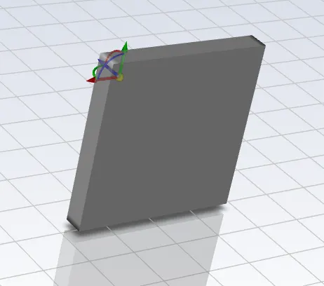
Processor:
Fins:
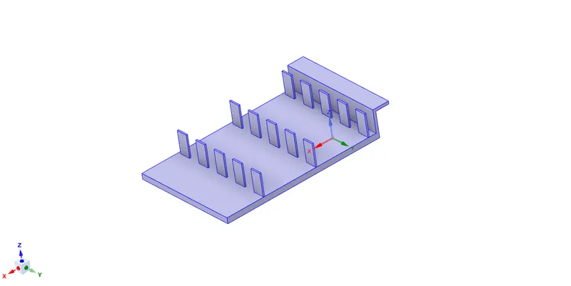
Note: Enable the SHARE TOPOLOGY
Mesh refinement:
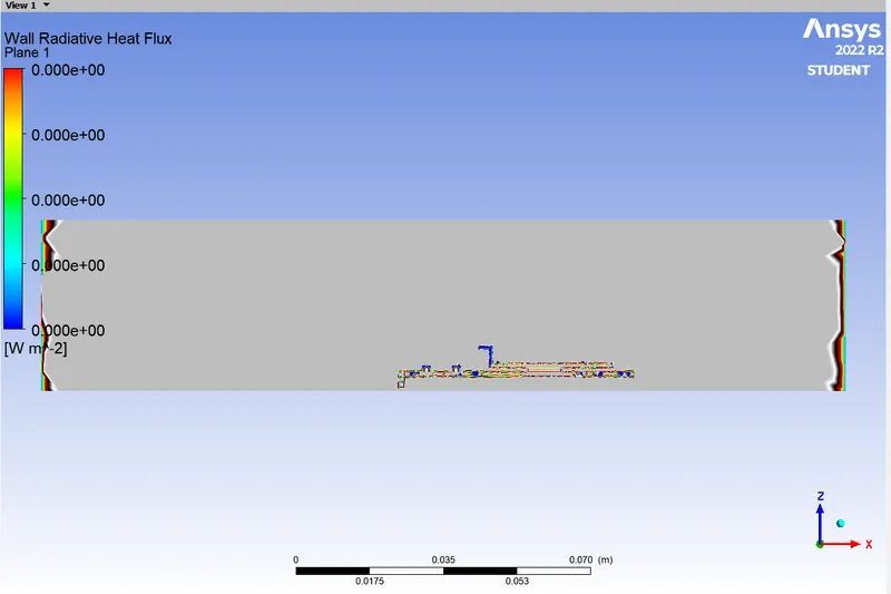
In this study, heat transfer from the heat generating Unit (Processor) will get dissipated by 2 methods, conduction via fins and base plate and convection by air, since the effect of radiation has not been taken into account.
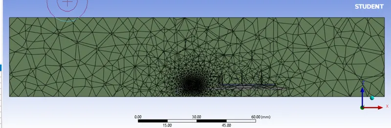
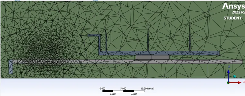
The geometries carrying the heat away from the processor are fins, base plate and vicinity fluid in these two media combined with fluid in contact with processor. Mesh refinement has been approached by changing the body sizing of these geometries.
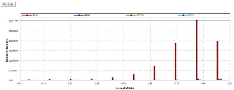
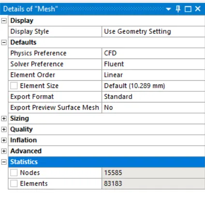
First simulation is taken for base mesh and no changes are made in base mesh. But for the second simulation the mesh is refined and body sizing is implemented for parts of geometry
BASE MESH:
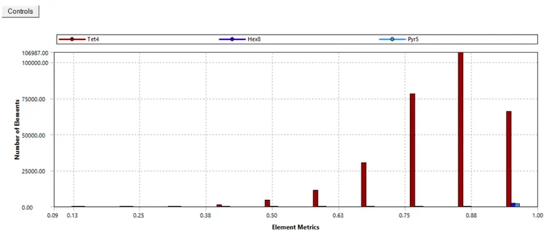
Quality:
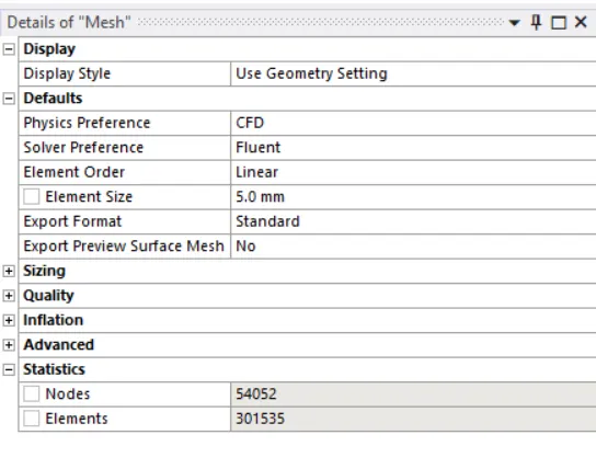
Element no:
SET UP:
- set up physics
- check energy eq.
- select k omega turbulent model
- create materials both solid and fluid
- air for fluid
- steel, copper and silicon for solid
- add materials for cell zone
- create boundary layers and add shell conduction
- layer trhickness 0.001 and thermal conduction 10
- select materials for wall
- between solid and fluid material will be of solid
- between 2 solids it will be of the solid which has no source
- add source for processor wall ie., 781520000
- initialize
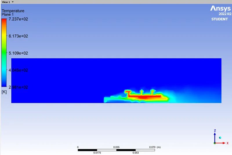
- create plane on zx axis and make 2 contour of temperature and velocity
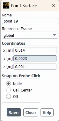
- create a point on processor for creating a vertex average temperature and note co-ordinate for other simulation
- start simulation and compare results for different simulation
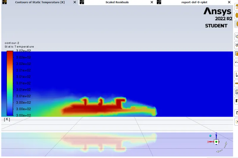
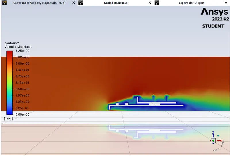
Case 1: 1 m/s
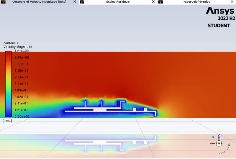
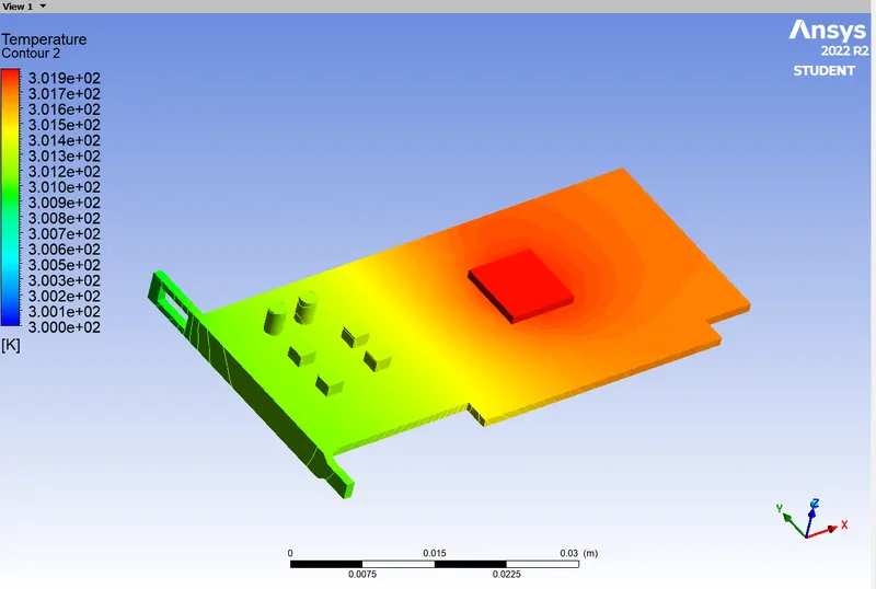
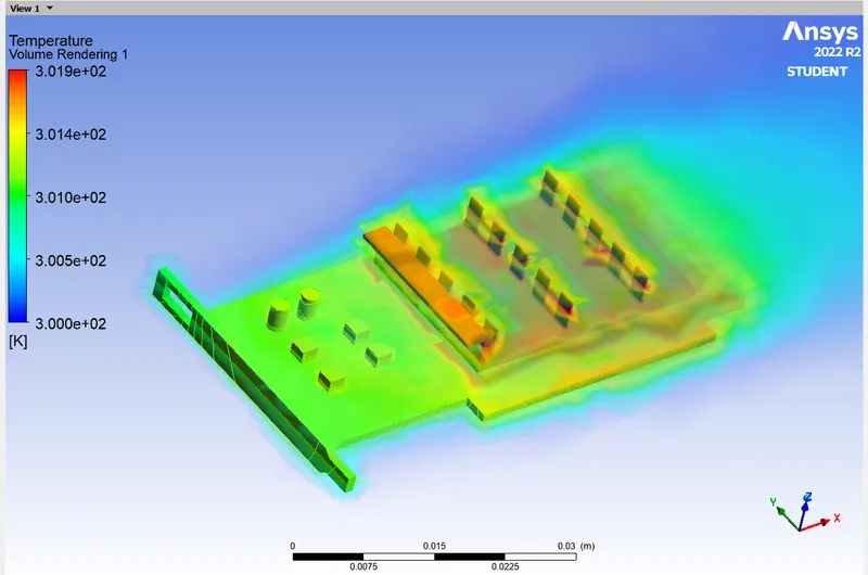
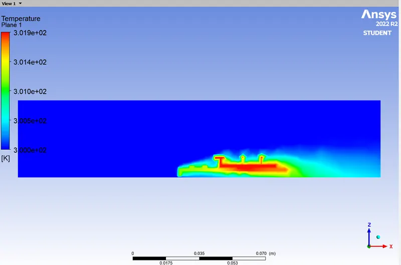
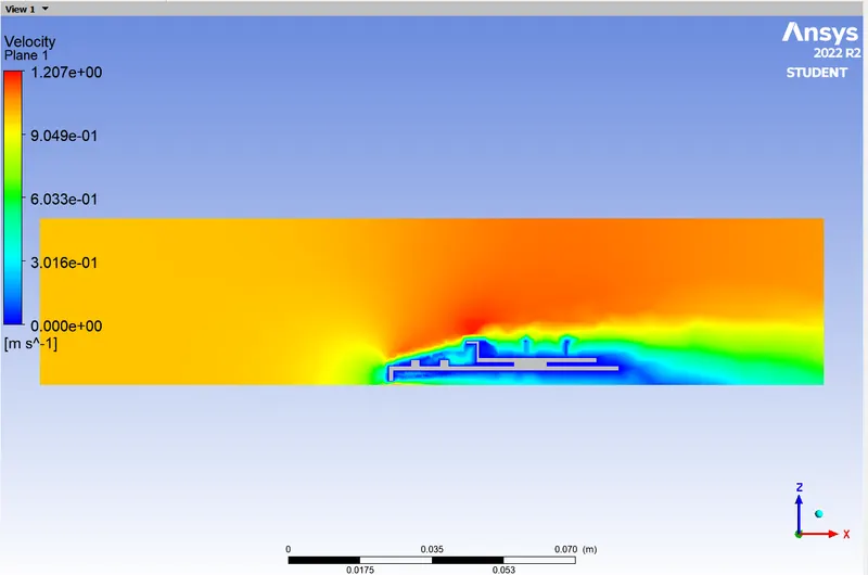
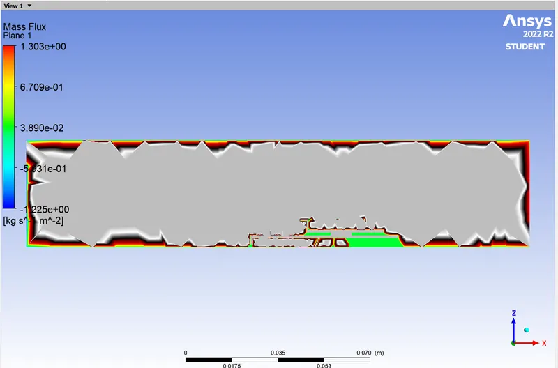
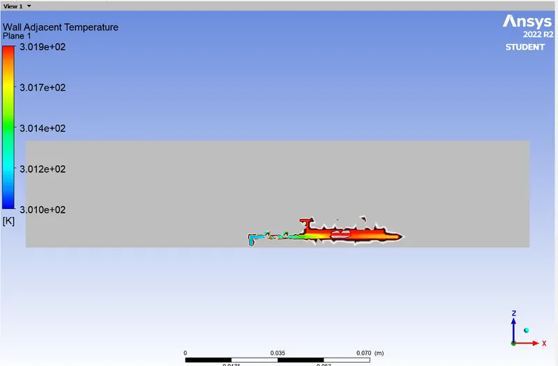
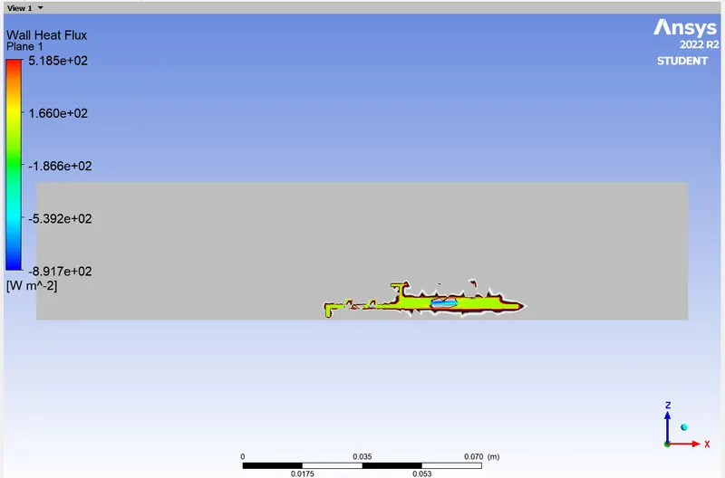
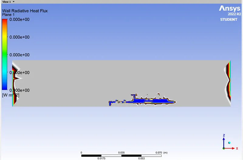
Case 2: 5 m/s
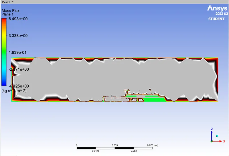
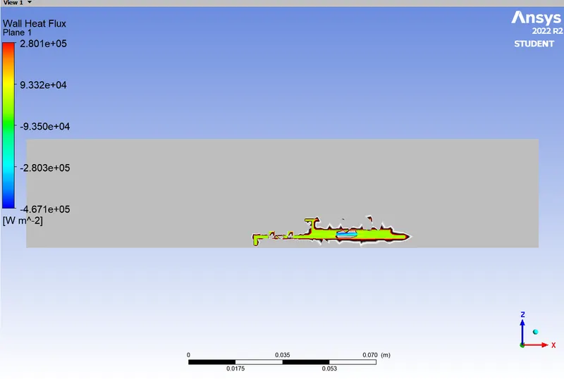
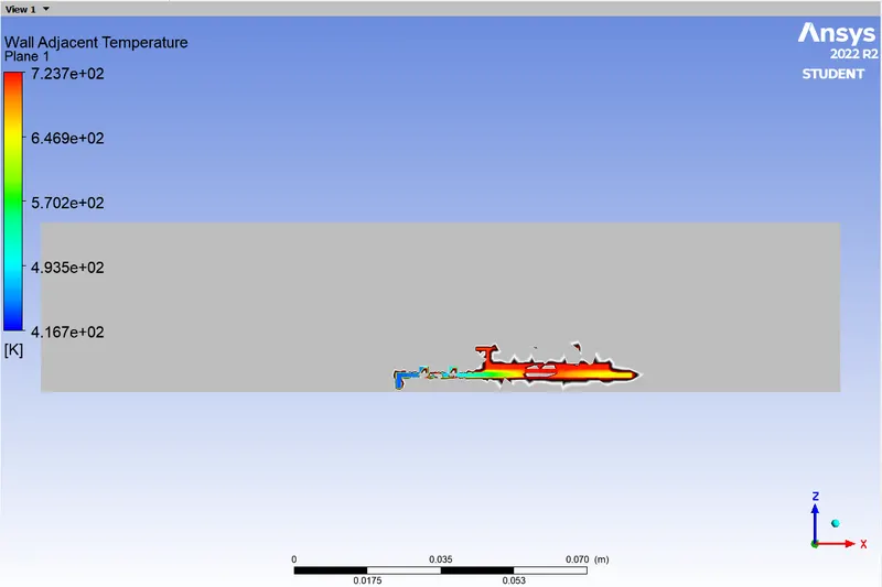
REFINED MESH:
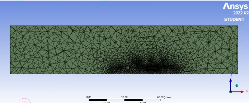
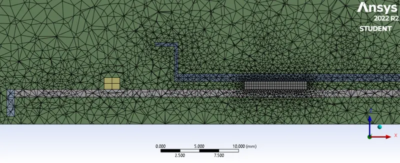
Quality:
Elements no:
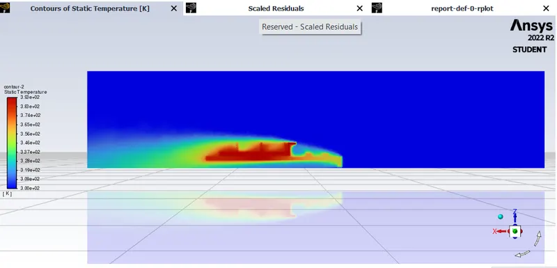
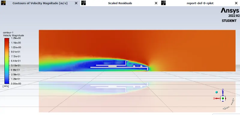
Case 1: v = 1 m/s
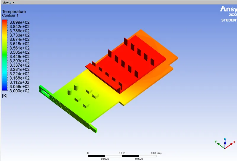
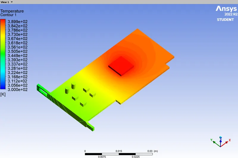
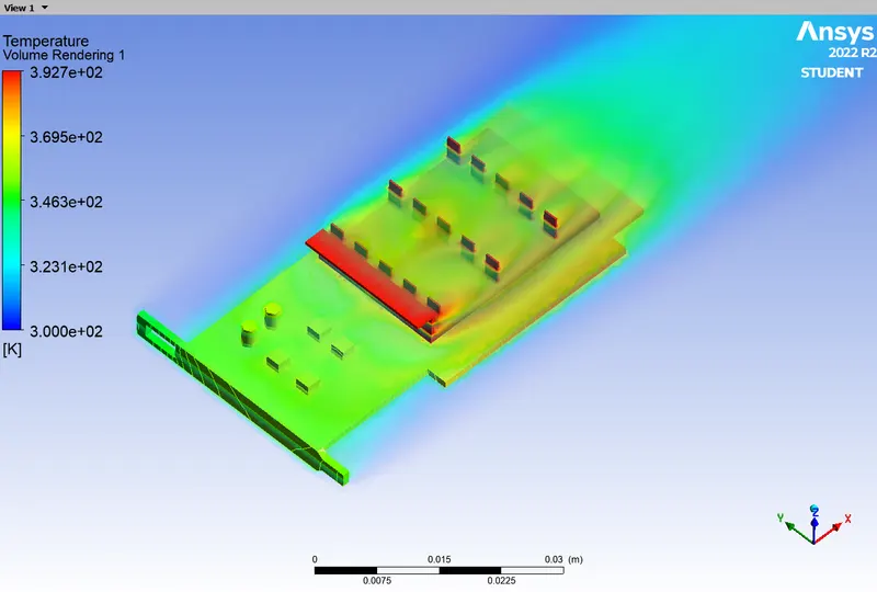
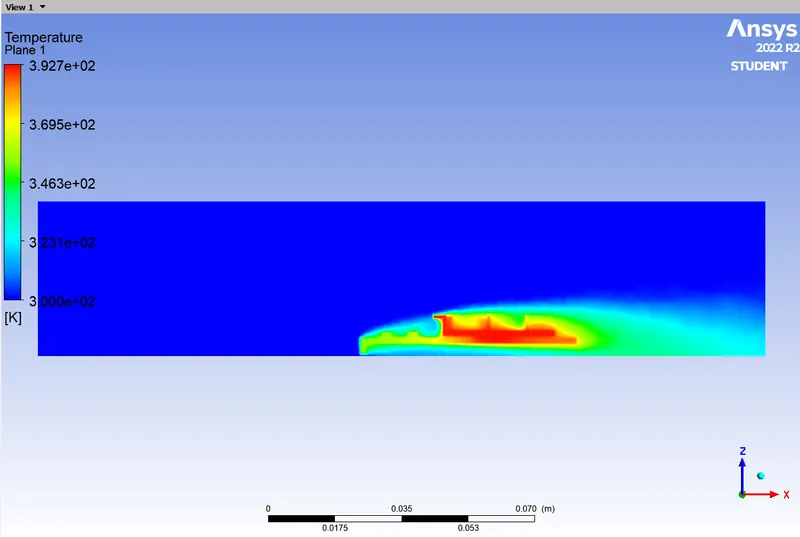

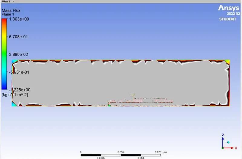
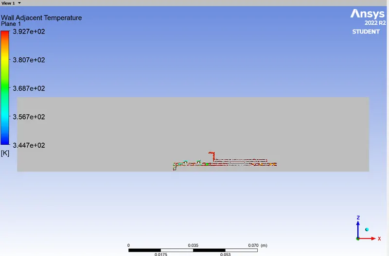
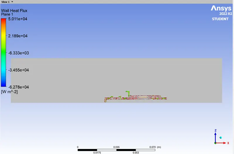
Case 2: v = 5 m/s
Conclusions:
From the above plots and contours we note the following observations and conclusions:
- Residuals do not provide information on the convergence to the steady state of the flow.
- The temperature monitor from above cases reach a steady state value and proves to be a great indicator of the convergence of the steady state problem.
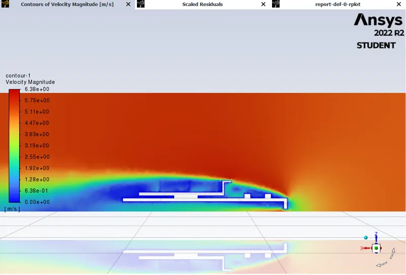
- As the velocity decreases, we observe that the thermal hot-spots are much stronger in magnitude and have an impact on larger regions of the graphic car. This observation is inline with the theoritical expectation of the effects of the convective heat transfer.
- The heat transfer coefficient near the fins is highest for inlet velocity of 5m/s. This observation is inline with the experimental trend.