Week 6 - CHT Analysis on a Graphics card
Aim: To Perform a steady-state conjugate heat transfer analysis on a model of a graphics card using Ansys 21R1.
Case 1:Baseline Mesh, Element size 10.9mm,nodes,number of elements elments
Case 2:Refined Mesh,Element size 0.6mm,nodes,number of elements elments And with varying velocities of air `1m/s^2,5m/s^2,10m/s^2`
Introduction:
CHT Conjugate heat transfer is heat transfer between fluids and solids i.e convection, conduction, and radiation. Conjugate in (CHT) suggests combined or coupled, This means analysis of heat transfer combining the heat transfer effects of solids and fluids present in the system. It is the study of conjugation of convection and conduction from solid and fluids.CHT analysis can precisely predict heat transfer by simultaneously solving all the relevant solid and flow field heat transfer processes. To simplify (CHT) analysis type allows for the simulation of heat transfer between solid and fluid domains by exchanging thermal energy at the interfaces between them.
The CHT approach, therefore, has benefits for those applications where heat transfer is either non-uniform or difficult to calculate empirically. the simulation of heat exchangers, cooling of electronic equipment, and general-purpose cooling and heating systems. for example conduction through solids, free and forced convection in fluids, and thermal radiation.
Need for the CHT Simulation
In the real world, there will always be an interaction between different states of materials like solid-fluid, mostly the interaction will be related to temperature. So it is important to study how the heat flow varies with changes of various parameters like the velocity of fluid, viscosity of a fluid.
The study of CHT helps us to design efficient ways to dissipate or retain the heat from a body. For example, In an automobile, the engine has many parts that are in contact with the heat. Air convection is one way to cool the engine bay, other ways is using a coolant jacket around the cylinders, the heat carried by the coolant is cooled by the natural forced convection of air from the fast-moving car. There are many applications where heat dissipation is crucial for efficiency. Like Ics, Computers, etc.
Graphics card:
A Graphics Card is a small piece of computer hardware that is used to produce images we see on the monitor. It is responsible for rendering an image on our monitor, this is done by converting data into a signal monitor can understand.
It performs actions very fastly and there is electricity passing through this so the generation of heat is obvious. An increase in temperatures of graphics cards above the limit leads to malfunctioning it. So there is a need to find effective ways to remove heat from the graphics card. To design, we need to understand how heat is dissipated from the graphics card so it is simulated in this challenge.
A basic graphics card model has a base on which other parts are mounted and electronic connections were made, a fin structure for the excess heat to dissipate from the processor, Some capacitors and electronic devices. This model is used in the simulation. It doesn't have all the features of the Graphics card but has major structures.
Problem-solving and modeling approach:
Geometry setup:
Importing Graphics card model into space claim
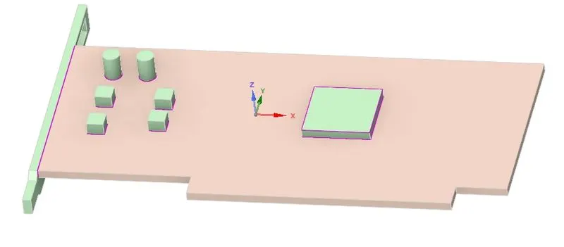
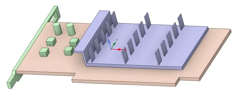
Share topology:
Topology is set to share then open the workbench and select the share after that the faces and objects that can share topology are selected and confirm share. This helps in creating the conformal mesh at the interfaces.

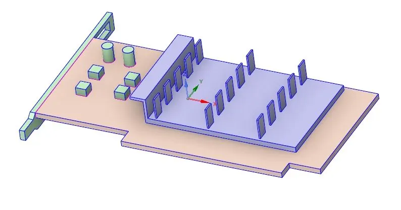
The pink and blue borders say that the topology is shared.
Meshing:
Open Meshing and name the entities, Then for the refined mesh create sizing for the base, processor, fins, and capacitors and give them sizing of 0.6mm. For the enclosure give the Mesh size as 0.4. This way the number of elements is within the limits of the student version and the required features are captured.
Refining the mesh helps in capturing the details. When the object is refined the mesh close to the object gets refined to conform with the object. So we can observe the parameters required clearly.
Pre-processing:
Open fluent and use the pressure-based model, set the method to simple and the viscous model to K-omega sst. Check the energy box as there is heat transfer occurring. Give the boundary conditions inlet velocity and heat generation

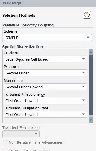
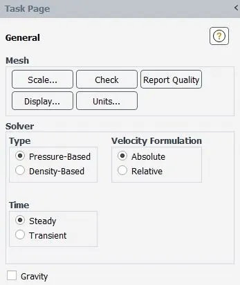
Energy is turned on as there is heat transfer
Inlet velocity: `1m/s^2,5m/s^2,10m/s^2`
Heat generation power is 10W
1561250000`W/m^3`
Materials:
Base: steel (Solid)
fins: aluminum (Solid)
processor: copper (Solid)
capacitors: copper (Solid)
select the cell zones correctly.
Enclosure fluid -air
All the other components are solids.
Case1:Baseline Mesh
Element size 10.9mm
Number of elements: 82315
nodes: 15494
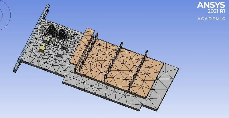

Mesh quality:
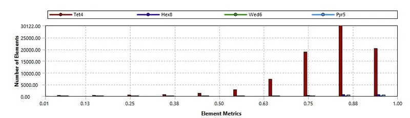
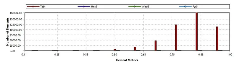
The mesh quality is good most numbers of elements are above 0.5
Residuals:
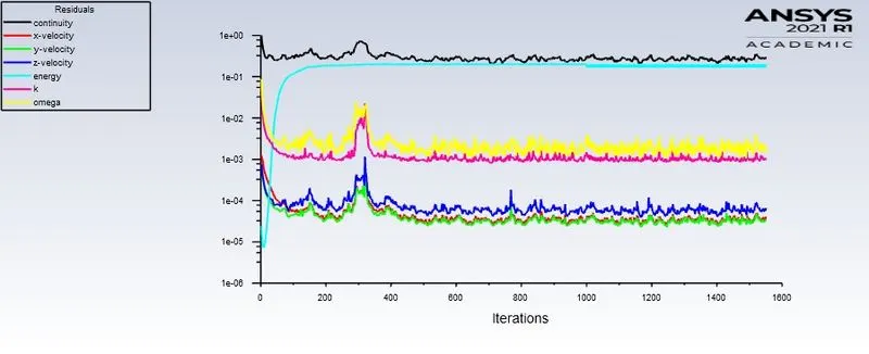
Converged at 1200 iterations
Temperature contour:
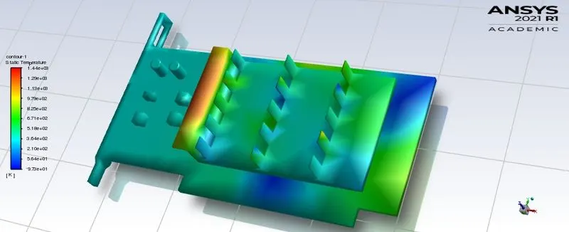
The max temperature is 1440k Temperature is not distributed uniformly as there are not enough elements present.
Velocity contour:
Velocity 1m/s^2
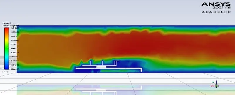
Max velocity is 1.21m/s^2
Case2:Refined Mesh
Create sizing for processor, Base, processor, fins and give element size of 0.6mm
For capacitors give element size 1mm
enclosure element size 4mm
Number of elements: 485436
nodes: 84335
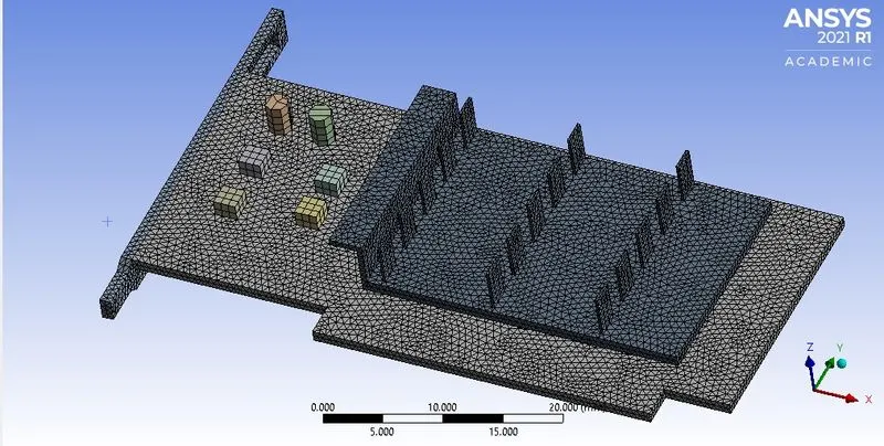

Mesh quality:
Case 2.a : Velocity 1m/s^2
The same meshing is used for all the velocities
Residuals:
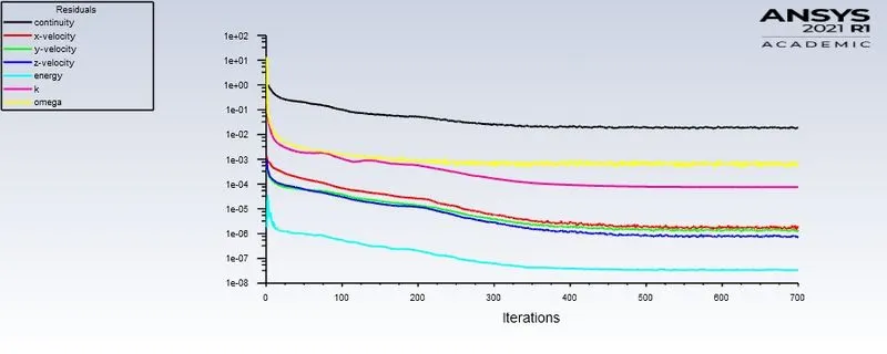
Convergence at 440 iterations
Temperature contour:
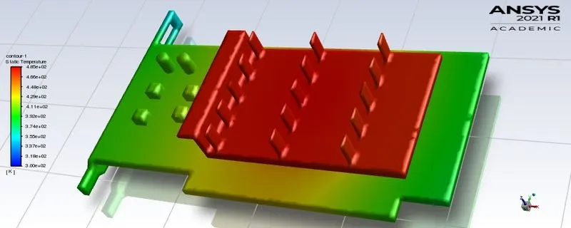
The hot spots are the fins and the processor there is no particular location of hotspots we can see when velocities of air increases.
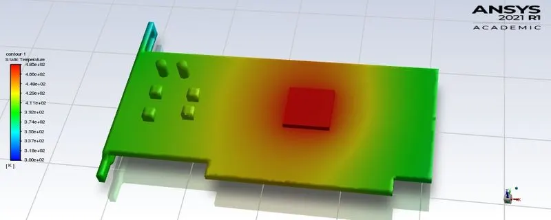
The maximum temperature is 483k
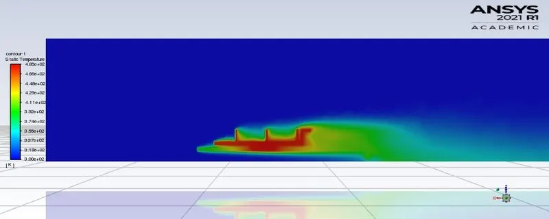
Velocity contour:
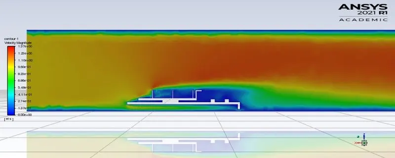
The maximum velocity is 1.37m/s^2
Case 2.b : Velocity 5m/s^2
Residuals:
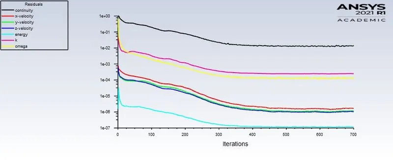
Converged at 550 iterations
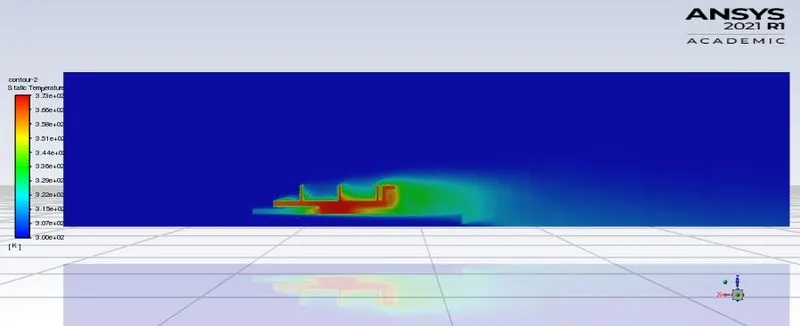
Temperature contour:
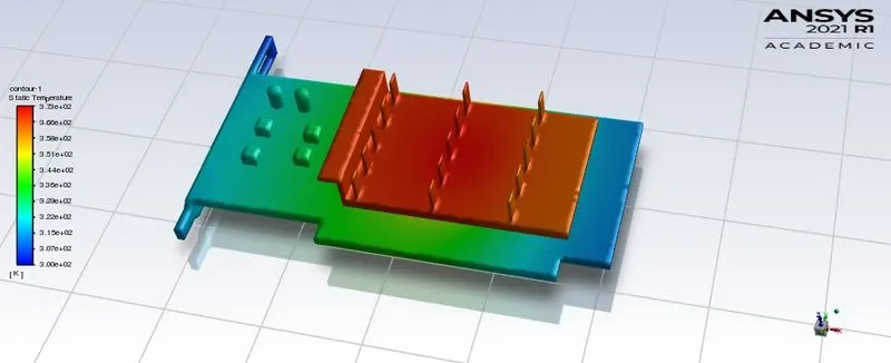
The hotspots are at the central row of fins
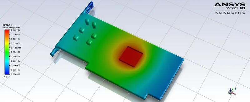
The maximum temperature is 373K
Velocity contour:
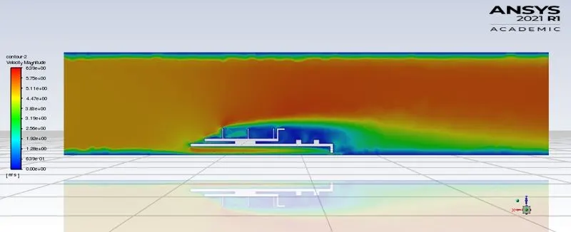
Maximum velocity is 6.33m/s^2
Case 2.b : Velocity 10m/s^2
Residuals:
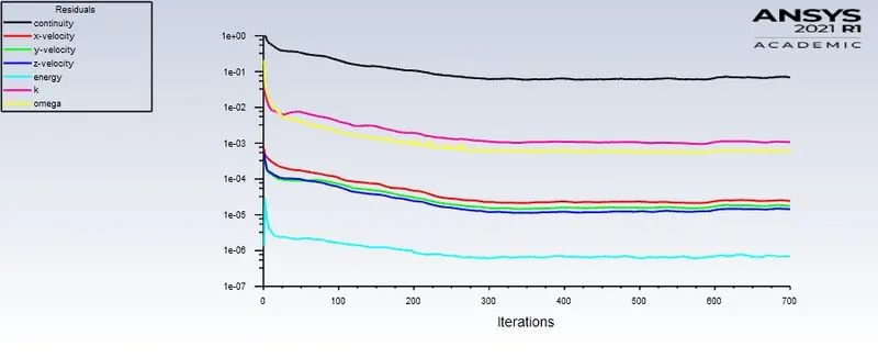
Converged at 620 iterations
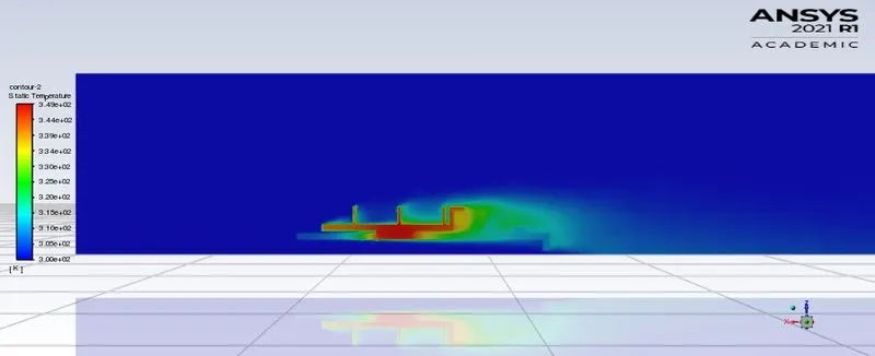
Temperature contour:
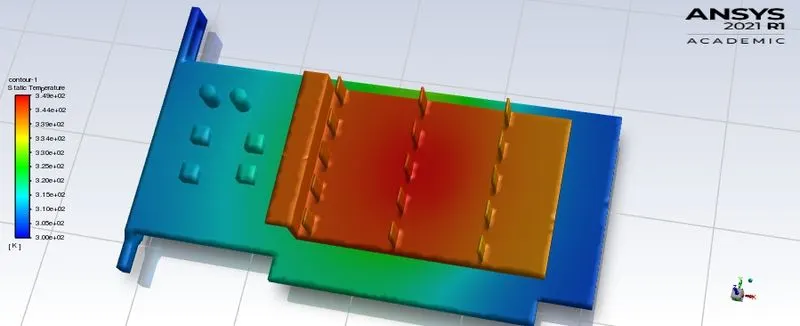
It is clearly seen that the hot spot is at the central row of the fins
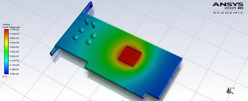
The maximum temperature is 345K
Velocity contour:
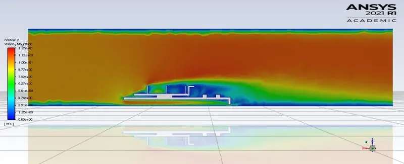
Maximum velocity is 12.5m/s^2
Table:
| Velocity (m/s^2) | Max Temperature (K) | Max Velocity (m/s^2) | Convergence | Max Heat transfer coefficient `W/(m^2k)` |
| 1(Baseline Mesh) | 1440 | 1.21 | 1200 | 137 |
| 1(Refined Mesh) | 480 | 1.37 | 440 | 868 |
| 5(Refined Mesh) | 373 | 6.33 | 550 | 2140 |
| 10(Refined Mesh) | 345 | 12.5 | 620 | 3472 |
Conclusion:
The results from the Refined mesh are more accurate than the baseline Mesh. The increase in the number of elements resulted in the uniform distribution of the temperature and we can visualize the temperature gradient in the fins and on the base.
An increase in velocity of air plays a good role in heat dissipation. The maximum temperature reached is decreasing with the increase in velocity. Thus increasing the heat transfer coefficient with the velocity. The heat transfer rate is increased with the increase in the velocity of air with the improved heat removal.