Week-6 Challenge: EV Drivetrain
1. Which types of power converter circuits are employed in electric and hybrid electric vehicle?
There are 3 types of power converters employed in electric or hybrid electric vehicles
- AC-DC rectifier
- DC-AC Inverter
- DC-DC converter
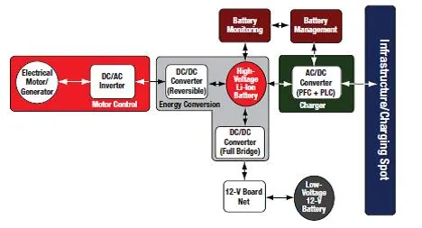
AC-DC Rectifier:
A rectifier is an electronic device that converts an alternating current into a direct current by using one or more P-N junction diodes. A diode behaves as a one-way valve that allows current to flow in a single direction. This process is known as rectification.
Its normal function inEV or HEV is charging batteries and keeping them in optimum conditions while, at the same time, providing DC power for other loads.
DC-AC Inverter:
An inverter is a device that converts DC power to the AC power used in an electric vehicle motor. The inverter can change the speed at which the motor rotates by adjusting the frequency of the alternating current.
from the car's 12-volt system—and converts it to the alternating-current (AC) power required by refrigerators, sump pumps, and most other devices.
Inverters also control the motor and convert it to a generator, transferring braking energy back into the battery.It acts like birectional device.
DC-DC converter:
In DC-DC converters there are many types
- Buck converter:A buck converter is used to step down voltage of the given input in order to achieve required output. Buck converters are mostly used for USB, Battery Charging such as auxillary batteries and power audio amplifiers .
- Boost converter:Boost converters can increase the voltage and reduce the number of cells. Two battery-powered applications that use boost converters are used in hybrid electric vehicles (HEV) and lighting systems. DC/DC converter is used to boost the Fuel Cell voltage and to regulate the DC-link voltage.
- buck boost converter:It has many advantages, such as noninverting voltage step-up and step-down characteristic in both motor operating modes, high efficiency, wide bandwidth, and input or output currents regulation because of their low ripple values.
2. An Electric Vehicle's powertrain with 72V battery pack in shown in the diagram below. The duty ratio for acceleration operation is 'd1' and for the braking operation the duty ratio is 'd2'.
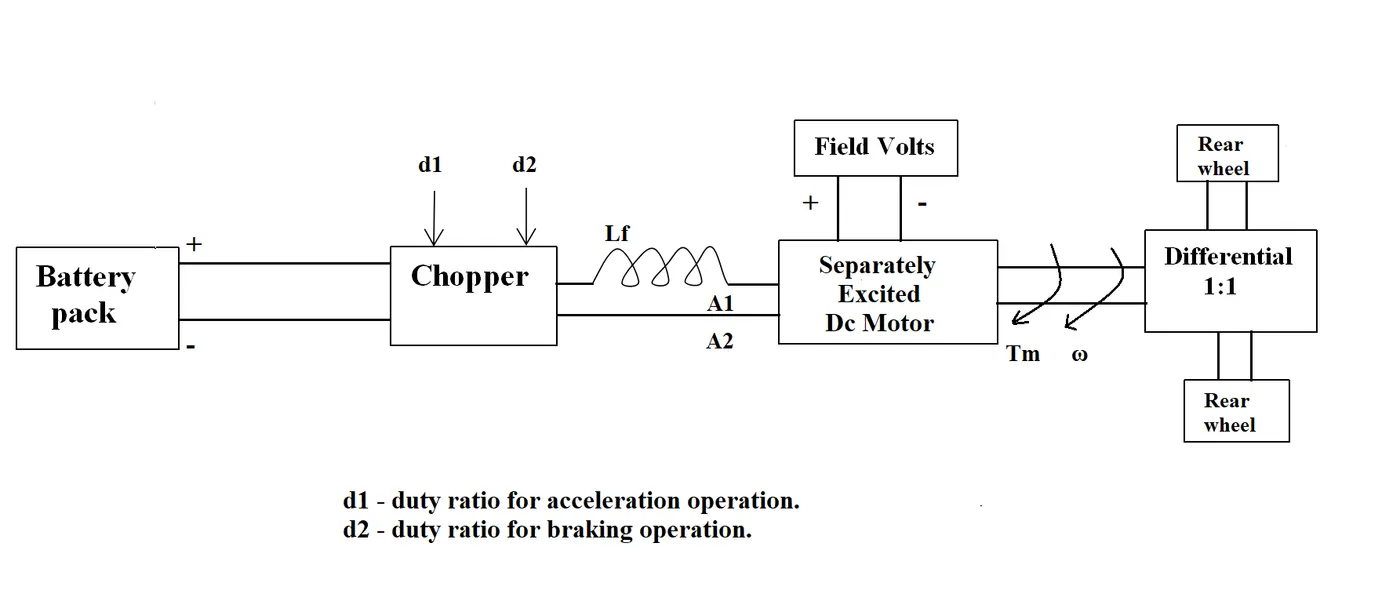
The other parameters of the electric vehicle is given below,
Motor and Controller Parameters:
Rated Armature voltage= 72 V
Rated armature current= 400 A
Ra= 0.5Ω, KΦ= 0.7 Volt second
Chopper Switching frequency= 400 Hz
The vehicle speed-torque characteristics are given by the below equation

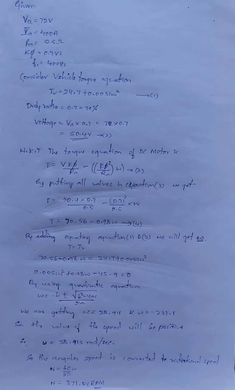
What is EV steady state speed if duty cycle is 70%?
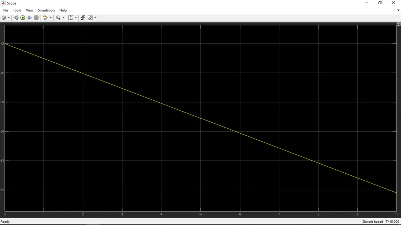
3. Develop a mathematical model of a DC Motor for the below equation using Simulink.
ω">ω=V/Kϕ">ϕ-Ra/(Kϕ">ϕ^2).T
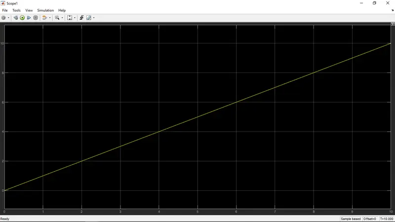
The simulation model for above mathematical equation is shown below
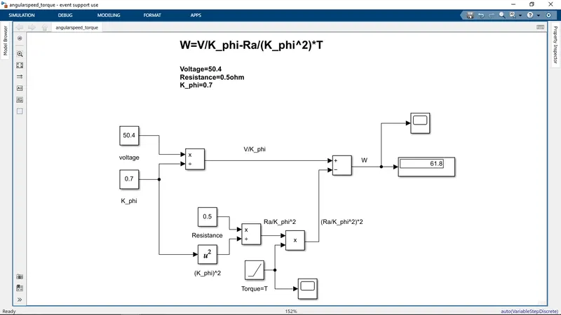
In the above model the torque is considered as ramp slope=1
The responce of the angular speed is shown beolw
4. Refer to the blog on below topic:
Induction Versus DC brushless motors by Wally Rippel, Tesla
Explain in brief about author’s perspective.
In author Wally Rippel's perceptive,
There is no one best engine type, rather there are different types of engines to suit personal requirements, such as price and performance. This is also true for electric vehicle drives.
The autor has done comparison in between 3phase induction motor and brushless DC motor.
the stators for the 3-phase induction motor and the DC brushless motor are virtually identical.The essential difference between the two machines is with the rotor.
In iduction motor, induced voltage exists across the shorted structure that is proportionate to this speed difference between the rotor and electrical frequency.
When a 3-phase induction motor is connected to utility type 3-phase power,the motor has the ability to start under load. No inverter is needed.They cannot operate from DC; AC is a must. Shaft speed is proportionate to line frequency. Hence, when used with utility power, they are constant speed machines.
Add an inverter and it becomes possible to power an induction machine from a battery or other DC source; variable speed also becomes possible simply by adjusting the inverter frequency. Still, torque performance is low compared with DC machines. Add some feedback loops such that the inverter produces the exact frequency that the motor “desires".
By adjusting magnetic field in Imduction motor ,at light loads the inverter can reduce voltage such that magnetic losses are reduced and efficiency is maximized.
With DC brushless, as machine size grows, the magnetic losses increase proportionately and part load efficiency drops. With induction, as machine size grows, losses do not necessarily grow. Thus, induction drives may be the favored approach where high-performance is desired; peak efficiency will be a little less than with DC brushless, but average efficiency may actually be better.
His conclusion is that DC brushless drives will likely continue to dominate in the hybrid and coming plug-in hybrid markets, and that induction drives will likely maintain dominance for the high-performance pure electrics.