Project - Speed Control of a Direct Current (DC) motor
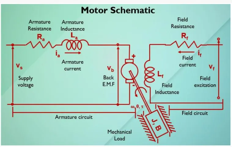
the openloop transfer function for the motor with the speed and supply voltage can be derived as
w(s)/Vs(s)=Kt/J*La*s^2+(J*Ra+B*La)*s+(b*Ra+Kt*Km)
the model simulated as per the above equation
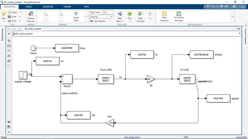
defining parameters
Now the DC motor is connected to PID controller to get DC motor speed as desired speed
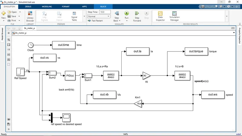
Initially PID controller having gains as Kp=1,Ki=1 and Kd=0 and the responce is
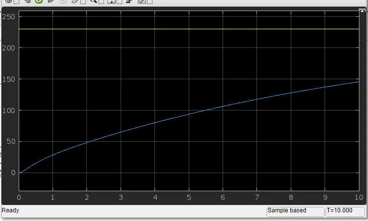
control design odjectives are
- settling time<2 secs
- overshoot <5%
- steady state error <1%
by keeping this in a mind, and using PID controller to get desired speed
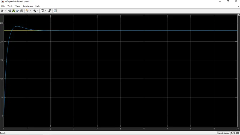
the plot responce and parameters shown below
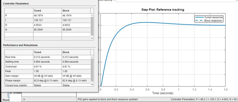
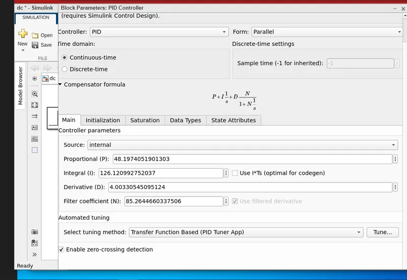
After using PID controller
- settling time=0.994 seconds
- overshoot=4.81%
- steady state error <1%
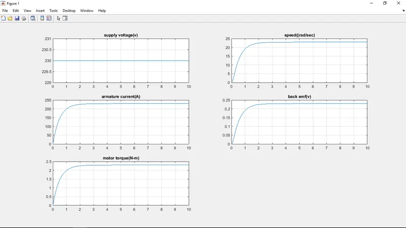
the output graph is shown below
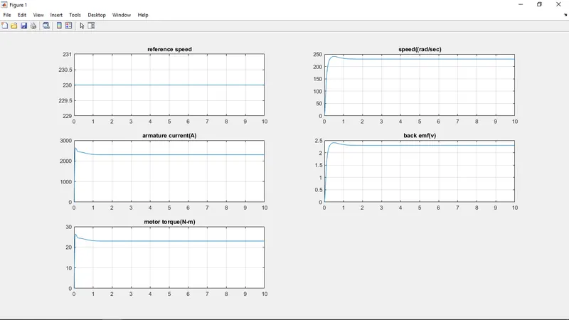
code for above graph
subplot(321);
plot(out.time,out.vs);grid;title('reference speed');
subplot(322);
plot(out.time,out.ws);grid;title('speed((rad/sec)');
subplot(323);
plot(out.time,out.Ia);grid;title('armature current(A)');
subplot(324);
plot(out.time,out.vb);grid;title('back emf(v)');
subplot(325);
plot(out.time,out.torque);grid;title('motor torque(N-m)');
graph of reference speed and desired speed