Week-7 Challenge: DC Motor Control
1. A. Explain a MATLAB demo model named ‘Speed control of a DC motor using BJT H-bridge’.
The simulation model of speed control of a dc motor using BJT H-bridge is shown below
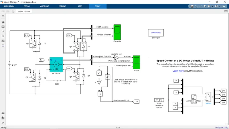
The Bipolar Junction Transistor (BJT) when used for power switching applications, operates as an IGBT. When it is conducting (BJT operating in the saturated region), a forward voltage Vf is developed between collector and emitter (in the range of 1 V). Therefore, the IGBT block can be used to model the BJT device.
The IGBT block does not simulate the gate current controlling the BJT or IGBT. The switch is controlled by a Simulink signal (1/0). The DC motor uses the preset model (5 HP 24V 1750 rpm). It simulates a fan type load (where Load torque is proportional to square of speed). The armature mean voltage can be varied from 0 to 240 V when the duty cycle (specified in the Pulse Generator block) is varied from 0 to 100%.
The H-bridge consists of four BJT/Diode pairs (BJT simulated by IGBT models). Two transistors are switched simultaneously: Q1 and Q4 or Q2 and Q3. When Q1 and Q4 are fired, a positive voltage is applied to the motor and diodes D2-D3 operate as free-wheeling diodes when Q1 and Q4 are switched off. When Q2 and Q3 are fired, a negative voltage is applied to the motor and diodes D1-D4 operate as free-wheeling diodes when Q2 and Q3 are switched off.
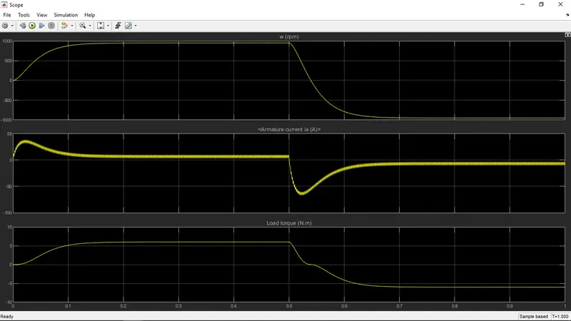
The motor starts in the positive direction with a duty cycle of 75% (mean DC voltage of 180V). At t= 0.5 sec., the armature voltage is suddenly reversed and the motor runs in the negative direction.
'Scope' shows motor speed, armature current and load torque
Scope shows currents flowing in BJT Q3 and diode D3.
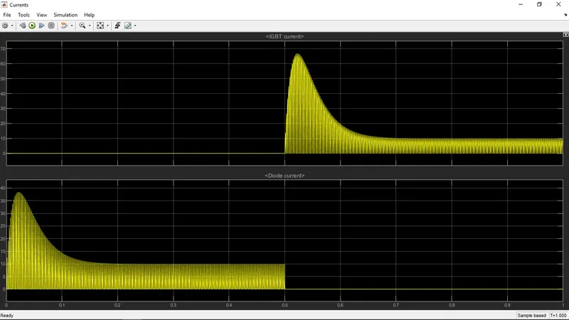
1. B. Comment on the armature current shoot-up from the scope results.
Starting Current in Induction Motor:
Starting current of induction motor is as high as 5 to 7 times the normal full load current. Therefore different starting of induction motor, methods such as (star delta starter, auto transformer starter and other starting methods) are employed in order to reduce the high starting currents of induction motor.
Why High Starting Currents:
Induction motor can be compared to an electrical transformer with the secondary short circuited. Primary winding of the transformer can be compared to the stator winding of the induction motor and the rotor winding is considered as the short circuited secondary winding of the transformer.
Induction motor circuit model is shown in the figure.
From the model of Induction motor we can observe that induction motor consists of two branch circuits which are in parallel
- Magnetizing component circuit
- Resistance and reactance circuit
Magnetizing component of current flowing through induction motor is proportional to the applied voltage and is independent of load on the motor similar to transformer .
Resistance and leakage reactance circuit consist of resistance and leakage reactance of stator and rotor of induction motor connected in series. A load resistance (variable) is connected in series to the fixed rotor and stator impedance. During starting of the motor, slip will be one. Therefore if we calculate the total impedance offered (stator and rotor impedance) to the inrush currents during starting of induction motor which is minimum resulting in high inrush currents during starting of the motor.
When 3 phase voltage applied across the stator winding for starting of induction motor, high inrush currents magnetize the air gap between the stator and rotor. An induces emf is generated in the rotor windings of the induction motor because of the rotating magnetic field. This induced emf produces electrical current in rotor windings. Current generated in the rotor windings produces a field which in turn produces torque to rotate the motor. Once the rotor starts picking up the speed, current drawn by the machine decreases. The time required for staring of the motor depends on the time required for the acceleration which depends on the nature of the connected load.
Disadvantages of High Starting Currents in Induction Motor:
High inrush currents drawn by induction motor during starting can result in large dip in connected bus voltages. This dip in bus voltages can impact the performance of other motors operating on the bus. Voltage dips during starting of large motors can trip some of the motors operating on the same bus. Care should be taken to limit the inrush currents during starting of the motor by employing proper starting methods
For large motors life of the machine depends on the number of startings. High inrush currents can cause increase in the temperature of the machine, damages the insulation and can reduce the life of the machine
1.C. Refer to the help section of ‘The Four-Quadrant Chopper DC Drive (DC7) block’. Compare it with the H-bridge model.
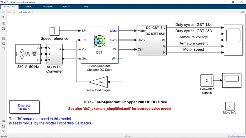
The 200 HP DC motor is separately excited with a constant 150 V DC field voltage source. The armature voltage is provided by an IGBT converter controlled by two PI regulators. The converter is fed by a 515 V DC bus obtained by rectification of a 380 V AC 50 Hz voltage source. In order to limit the DC bus voltage during dynamic braking mode, a braking chopper has been added between the diode rectifier and the DC7 block.
The first regulator is a speed regulator, followed by a current regulator. The speed regulator outputs the armature current reference (in p.u.) used by the current controller in order to obtain the electromagnetic torque needed to reach the desired speed. The speed reference change rate follows acceleration and deceleration ramps in order to avoid sudden reference changes that could cause armature over-current and destabilize the system. The current regulator controls the armature current by computing the appropriate duty ratios of the 5 kHz pulses of the four IGBT devices (Pulse Width Modulation). For proper system behaviour, the instantaneous pulse values of IGBT devices 1 and 4 are opposite to those of IGBT devices 2 and 3. This generates the average armature voltage needed to obtain the desired armature current. In order to limit the amplitude of the current oscillations, a smoothing inductance is placed in series with the armature circuit.
We can observe the motor armature voltage and current, the four IGBT pulses and the motor speed on the scope. The current and speed references are also shown.
The motor is coupled to a linear load, which means that the mechanical torque of the load is proportional to the speed.
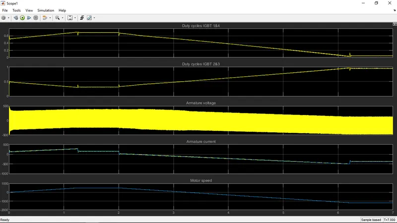
The speed reference is set at 500 rpm at t = 0 s. Observe that the motor speed follows the reference ramp accurately (+400 rpm/s) and reaches steady state around t = 1.3 s.
The armature current follows the current reference very well, with fast response time and small ripples. Notice that the current ripple frequency is 5 kHz.
At t = 2 s, speed reference drops to -1184 rpm. The current reference decreases to reduce the electromagnetic torque and causes the motor to decelerate with the help of the load torque.
At t = 2.2 s, the current reverses in order to produce a braking electromagnetic torque (dynamic braking mode). This causes the DC bus voltage to increase.
At t = 3.25 s, the motor reaches 0 rpm and the load torque reverses and becomes negative. The negative current now produces an accelerating electromagnetic torque to allow the motor to follow the negative speed ramp (-400 rpm/s). At t = 6.3 s, the speed reaches -1184 rpm and stabilizes around its reference.
Comparison between 4quadrant chopper and BJT H-bridge model:
- 4quadrant chopper can operates in all 4 modes but BJT H bridge can operate only in two modes
- In 4 quadrant chopper regenerative braking is possible ,but in H-bridge regenerative breaking is not possible
- In 4 quadrant chopper 2 PI regulators (speed regulator and current regulator)are used to obtain electromagnetic torque needed to reach the desired speed and control the armature current and stabilisze the sysyem, but in H-bridge PI regulator is not used
- 4 quadrant chopper is a elecronic switch that is used to interupt one signal under the control of another,but H-bridge is a elctronic circuitnthat switches the polarity of voltage applied to the load
- 4 quadrant model gives better efficiency and high energy storage than H-bridge
2. Develop a 2-quadrant chopper using simulink & explain the working of the same with the relevant results. (Refer to article - Multiquadrant operation of motor )
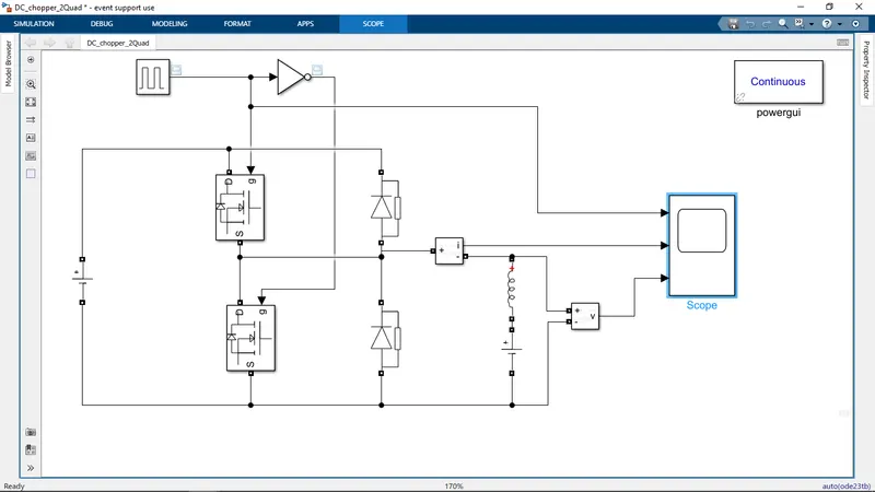
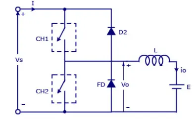
In this type of Chopper, the average voltage will be always positive but the average load current might be positive or negative. The two Switches CH1 and CH2 should not be turned on simultaneously as the combined action may cause a short circuit in supply lines. For regenerative braking and motoring these type of chopper configuration is used.
We will always get a positive output voltage V0 as the freewheeling diode FD is present across the load. When the chopper CH1 is on the current flows from source to load. The inductor stores energy. When Ch1 turn OFF the freewheeling diode starts conducting and the output voltage v0 will be equal to Vs. The direction of the load current i0 will be reversed. The current i0 will be flowing towards the source. The load current will be negative when the CH2 is on. The current completes its path through diode D2.
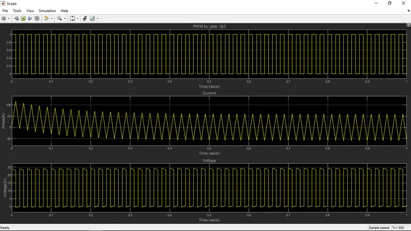
The simulation is done using 24V supply voltage and 12V used as exciting voltage at output side
The pulse is distributed to the mosfet -1 of 50Hz and usind NOT gate the pulse is distribuded to mosfet -2
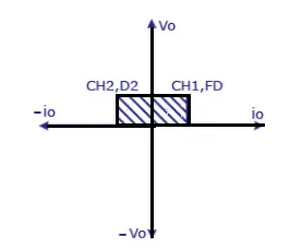
As per the above quadrant diagram we are getting positive voltage at the output and when motoring condition current positive and the when regenerative braking the current is negative
3. Explain in a brief about operation of BLDC motor.
Working Principle:
BLDC motor works on the principle similar to that of a brushed dc motor The Lorentz force law which states that whenever a current carrying conductor placed in a magnetic field it experiences a force. As a consequence of reaction force, the magnet will experience an equal and opposite force. In the BLDC motor, the current carrying conductor is stationary and the permanent magnet is moving.
Working:
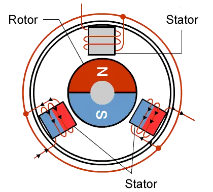
It often helps to explain how a brushed DC motor works first, as they were used for some time before brushless DC motors were available. A brushed DC motor has permanent magnets on the outside of its structure, with a spinning armature on the inside. The permanent magnets, which are stationary on the outside, are called the stator. The armature, which rotates and contains an electromagnet, is called the rotor.
In a brushed DC motor, the rotor spins 180-degrees when an electric current is run to the armature. To go any further, the poles of the electromagnet must flip. The brushes, as the rotor spins, make contact with the stator, flipping the magnetic field and allowing the rotor to spin a full 360-degrees.
A brushless DC motor is essentially flipped inside out, eliminating the need for brushes to flip the electromagnetic field. In brushless DC motors, the permanent magnets are on the rotor, and the electromagnets are on the stator. A computer then charges the electromagnets in the stator to rotate the rotor a full 360-degrees.
How ESC works(Electronic speed controller):
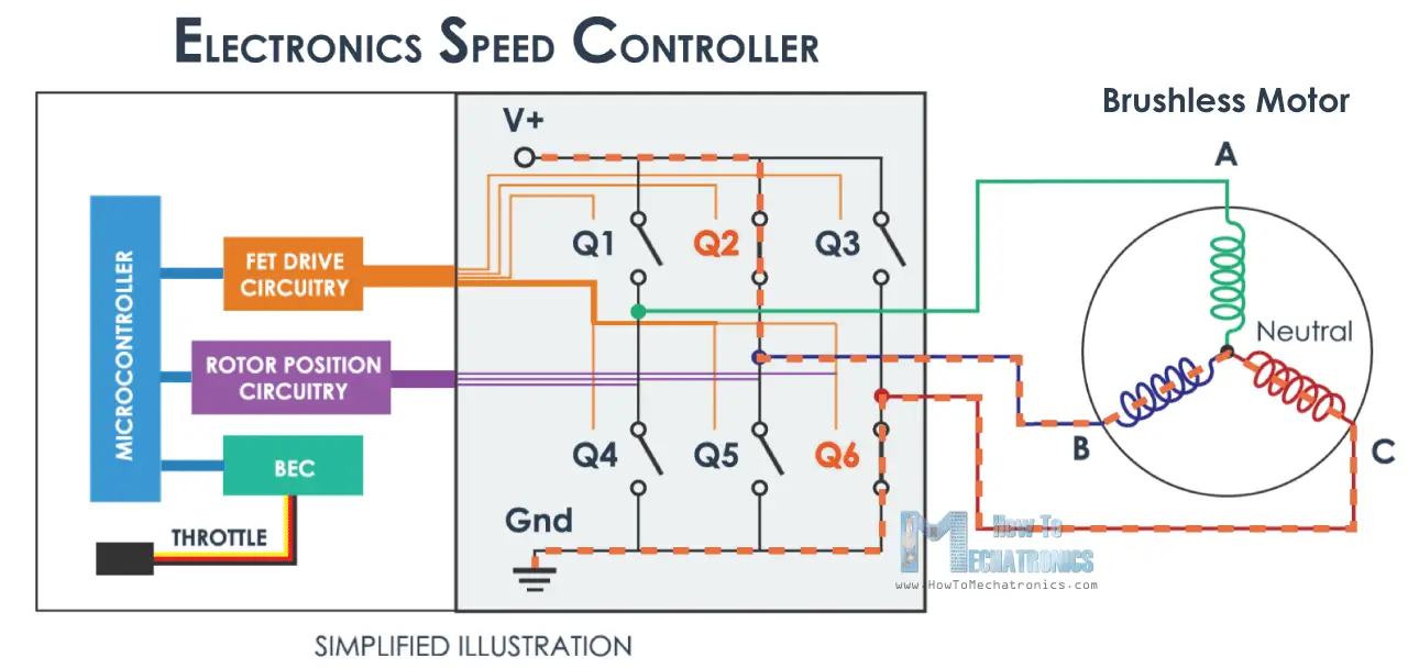
An ESC or an Electronic Speed Controller controls the brushless motor movement or speed by activating the appropriate MOSFETs to create the rotating magnetic field so that the motor rotates. The higher the frequency or the quicker the ESC goes through the 6 intervals, the higher the speed of the motor will be.
However, here comes an important question, and that’s how do we know when to activate which phase. The answer is that we need to know the position of the rotor and there are two common methods used for determining the rotor position.
The first common method is by using Hall effect sensors embedded in the stator, arranged equally 120 or 60 degrees from each other.
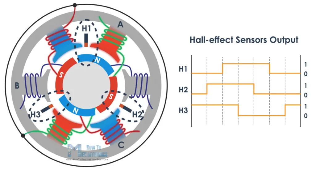
As the rotors permanent magnets rotate the Hall-effect sensors sense the magnetic field and generate a logic “high” for one magnetic pole or logic “low” for the opposite pole. According to this information the ESC knows when to activate the next commutation sequence or interval.