Project 1
I choose first 3 topologies for my project 1
1.Answer:
here we can see below first topology of buck converter and design calculations
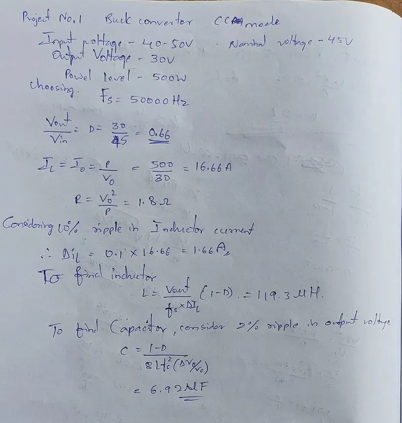
here I choosed only 45V as input voltage but in simulation design we can see repeating sequence of 40 to 50V as Input voltage
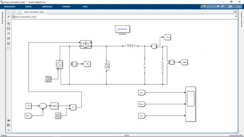
The buck converter is connected with closed loop because Input votage is varying from 40 to 50V.so we need to get desired 30V output for any input voltage
Output voltage is subtracted from 30V refernce voltage and that is connected to PID controller .PID will tune error signal and that is compared with pulse generator .
this is how the closed loop works
The required plots are shown below
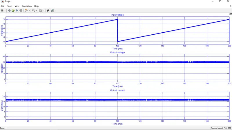
We are getting 30V as ouput for all Input voltage
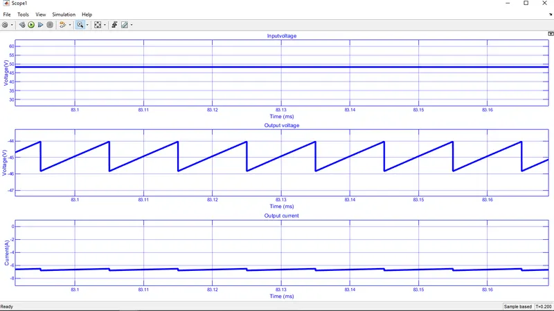
zoomed view For see the ripple in output voltage
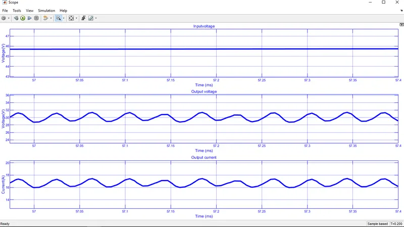
we choosed 6.92uF to get 2% ripple in Output votage and we are getting 2% ripple
2 Answer:
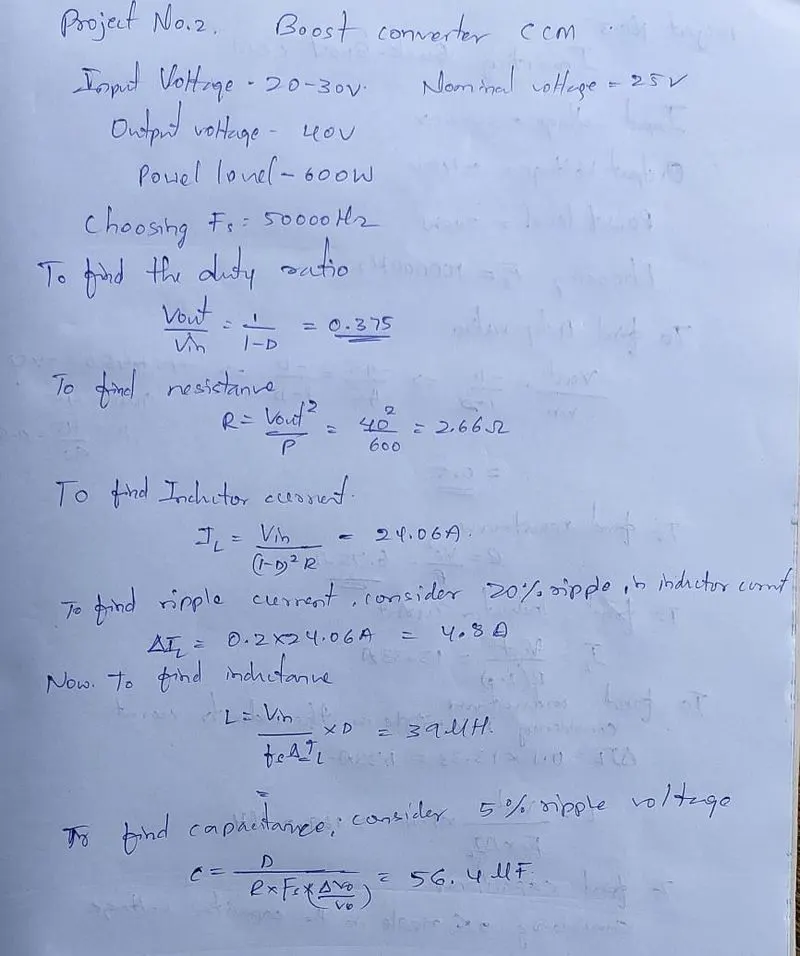
here we can see below second topology of boost converter and design calculations
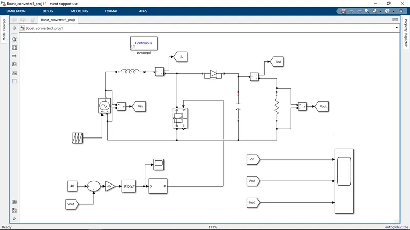
Boost coverter simulation design we can see below
Here we can see Input voltage of boost converter is connected to repeating sequence of 20 to 30V
To get desired constant output voltage boost convetrer is connected to closed loop
In closed loop Output voltage is subtracted from reference voltage of 40V and that error signal is send to PID controller with 1/200 gain
After tuned PID signal is send to PWM generator and that is connected to gate of mosfet
Now we can see the output plots below
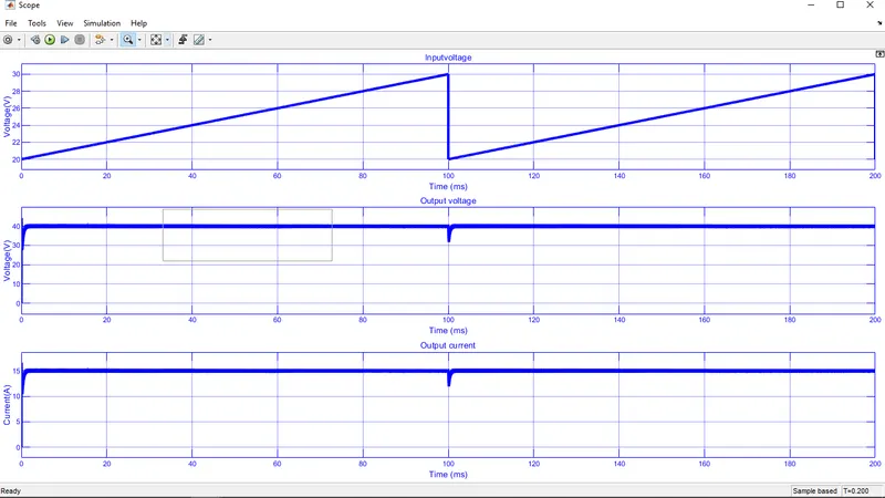
Here we can see the Output voltage of 40V for all Input voltage
zoomed version of above plot we can see below
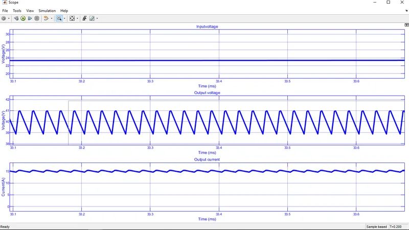
In output voltage we are getting 5% ripple for 56.4uF capacitor
3 Answer:
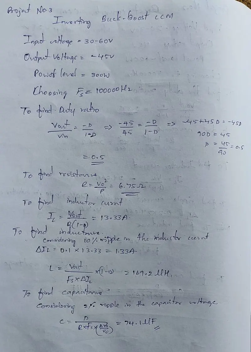
here we can see below third topology of Inverted buck boost converter and design calculations
Inverting buck boost converter simuation design we can see below
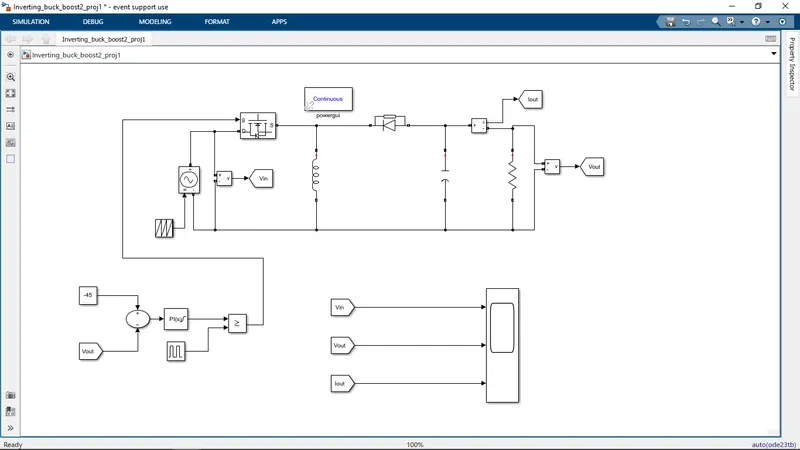
Here we can see Input voltage of buck boost converter is connected to repeating sequence of 40 to 50V
To get desired constant output voltage the Inverting buck boost convetrer is connected to closed loop
The Output voltage is subtracted from reference voltage of -45V and that error signal is sent to PID tuner.after tuning that signal is compared with pulse generator
and it is connected to gate of mosfet
Below we can see the required plots of converter
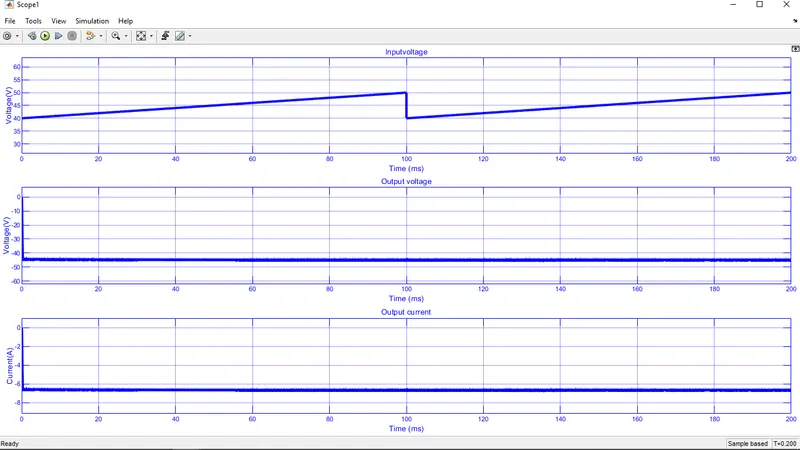
And we are getting -45V for all input voltage
here we can see the zoomed view of above plots