Project 2
Design of interleaving DC/DC converter system for a data centre application has following specifications
and calculation of interleaving converter is shown below
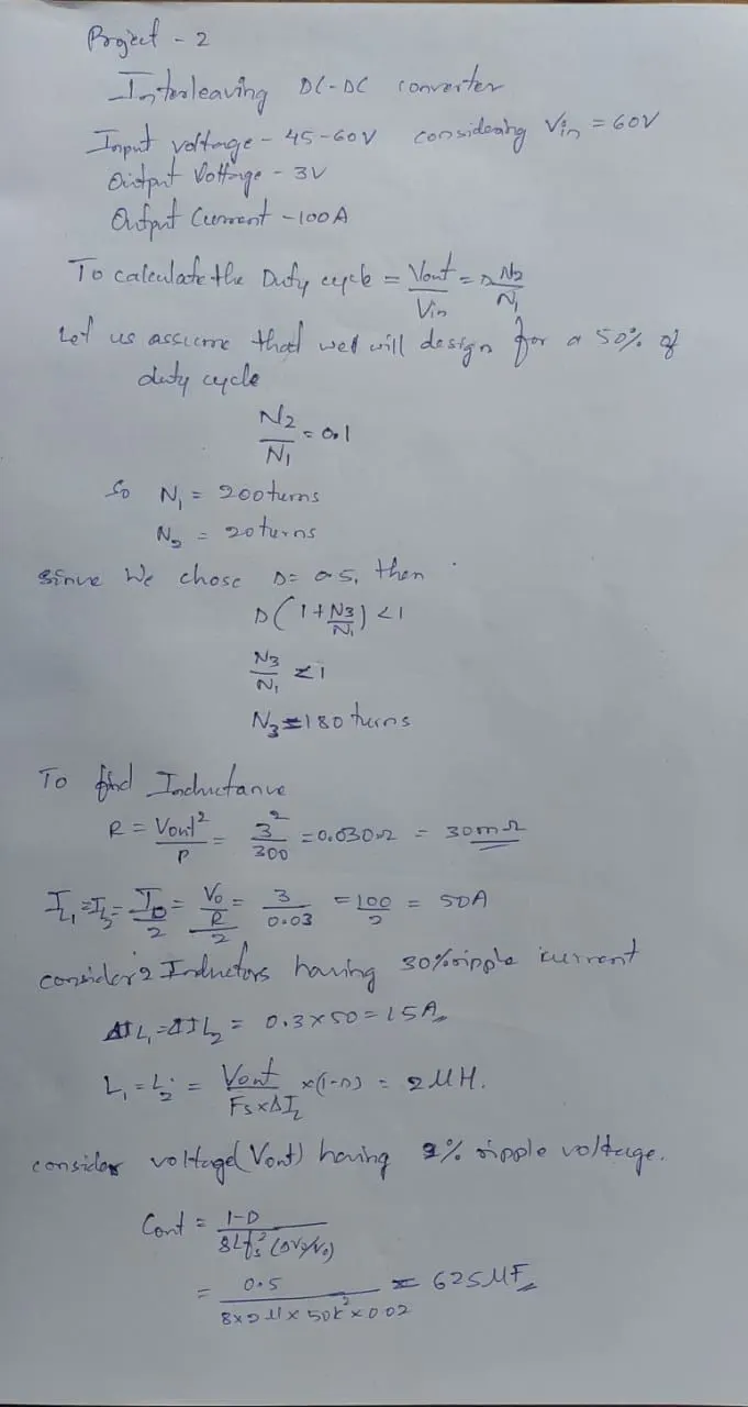
here we can see we using 3mohms as load resistor to get 100A as load current,
indoctance of 2uH to get 30%ripple in the indoctor current and 0.625mF to get 2%ripple in the output voltage
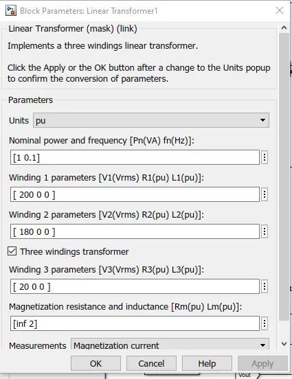
we chose 200 primary turns and 20 as secondary turns because 60V need to convert 6V and 180 as tertiary turns because
(N3/N1)*D>1
using isolated transformer we can convert high voltage ratio and efficiency is higher
D=0.5 because 6V of secondary volt need to be convert 3V
IL1=IL2=50A because here we using multiphase system two create parallel converter
The simulation design of Interleaving converter is shown below
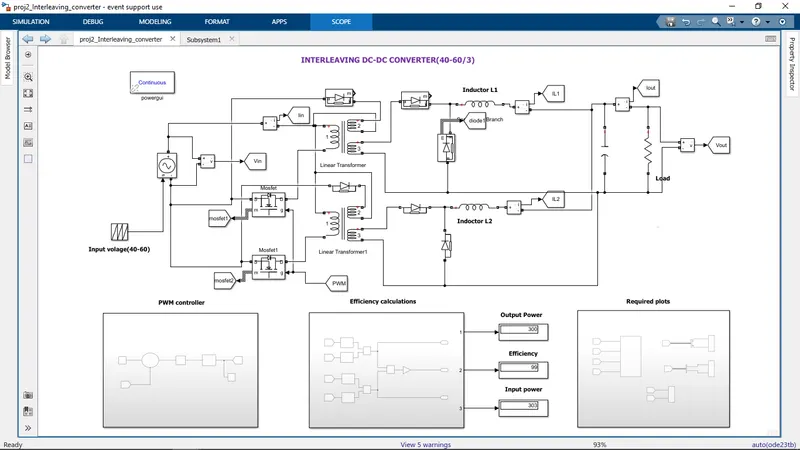
Above we used two forward converter to create multiphase system.Here the converter is capable of convertion of 40-60V to 3V using isolated transformer turns ratios.
The use of Interleaving converter is it reduces a ripple current in both the input and output currents and it reduces losses in indoctor and iron loss in transformer
totally use of interleaving converter improves the efficiency of the converter.The design is simulated considering all the mosfets and diodes are ideal and
it has closed loop gate driver
Gate driver:
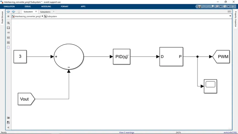
the intension of using closed loop PWM generator to get constant 3V output for all input varying voltages
here we can see the output voltagre is subtracted from 3V reference voltage and this error signal is tuned in PID controller
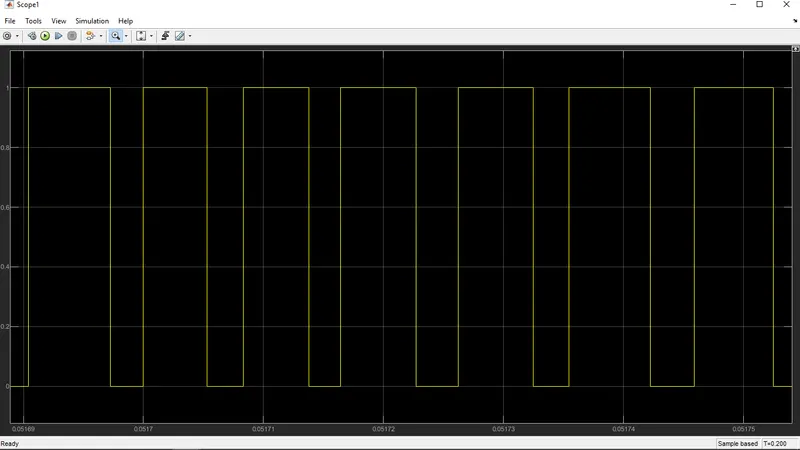
and that is given to PWM generator of 50000Hz and the PWM we are getting is shown below
And we are getting 99% efficiency
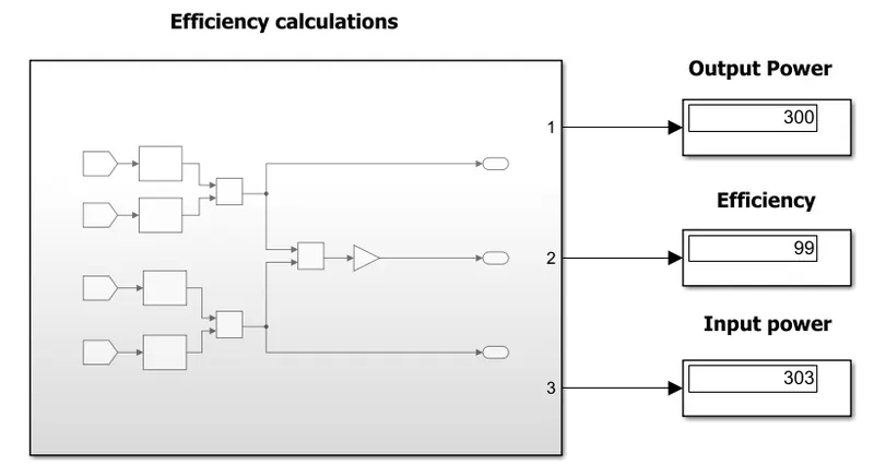
The logic behind the effciency calculations is shown below
Efficiency Calculator:
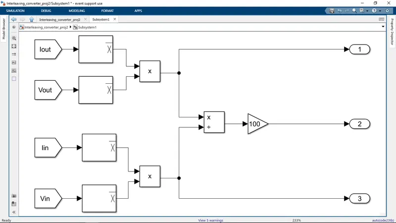
efficiency=(Output/Input)*100
so the output voltages and currents are multplied and that is devided by product of Input voltages and currents
the use of mean block is to get average values
Now the Input and Output voltage and currents we can see beolw
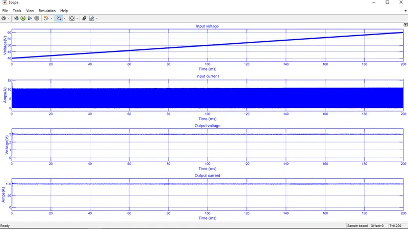
zoomed version of above plots
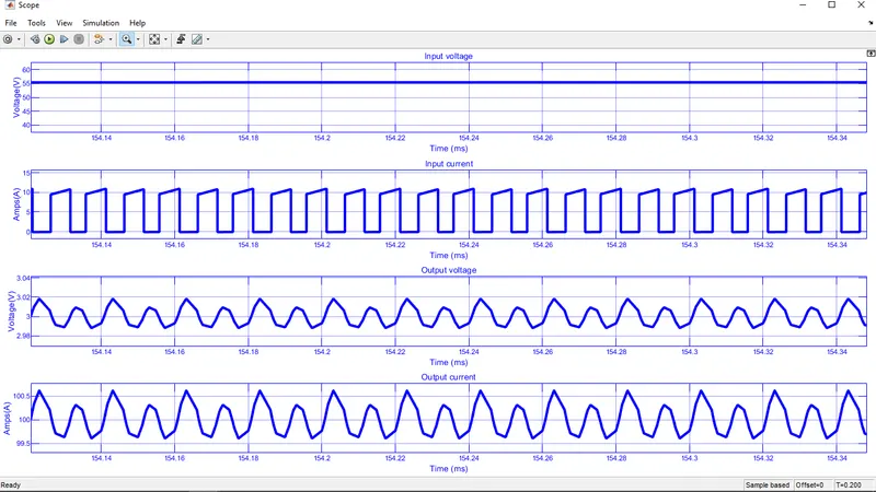
here we can see that the output of 3V is coming for all 40 to 60V input and we are getting almont 2% ripple in output voltage.
the Input current is 10A and the load current is 100A
The inductors currents of both the converter we can see below
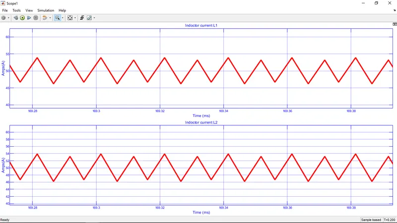
By seeing above plot we can conclude that inductor currents are having less ripple current
and that is around 8A.according to design it should be 15A
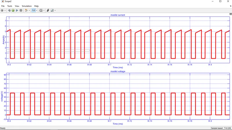
The mosfet current and voltage of both the forward converters are same and that is shown below
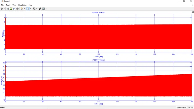
zoomed view of above plot
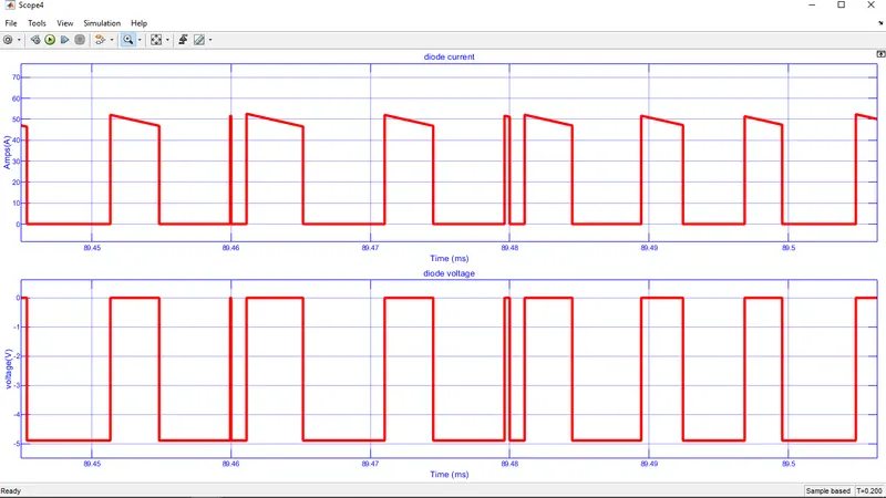
Diode current and voltages of both the load side diodes we can see below
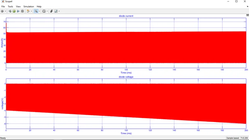
zoomed version of above plot is shown below