Week-6 Challenge: EV Drivetrain
1. Which types of power converter circuits are employed in electric and hybrid electric vehicle?
ANS:
Rectifier:
This circuit helps us in the conversion of alternating current (AC) to direct current (DC). This involves a device that only allows one-way flow of electric charge. In EVs, this is used to charge the batteries through a direct AC input from charging station or from MGU.
Inverter:
This does the exact opposite to rectifier. This converts DC to AC. As we know, EVs have DC battery source as the main source of supply and usage of Induction motors are common and these need the AC supply. Hence, in these scenarios, we use the Inverter circuits to convert DC to AC.
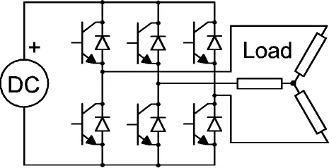
The above image is an example of inverter circuit for 3-phase AC generation.
DC to DC Converters:
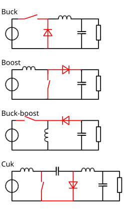
As you know there are plenty of load devices in a car let alone a EV. Particularly the new generation cars come with so may sensors and feedback and UI systems, which all needs different power input levels in DC. These are realised by DC-DC converters. For eg: A headlight may need a different voltage input compared to a Instrument cluster.
Below are some of the common DC-DC converters.
2.An Electric Vehicle's powertrain with 72V battery pack in shown in the diagram below. The duty ratio for acceleration operation is 'd1' and for the braking operation the duty ratio is 'd2'.
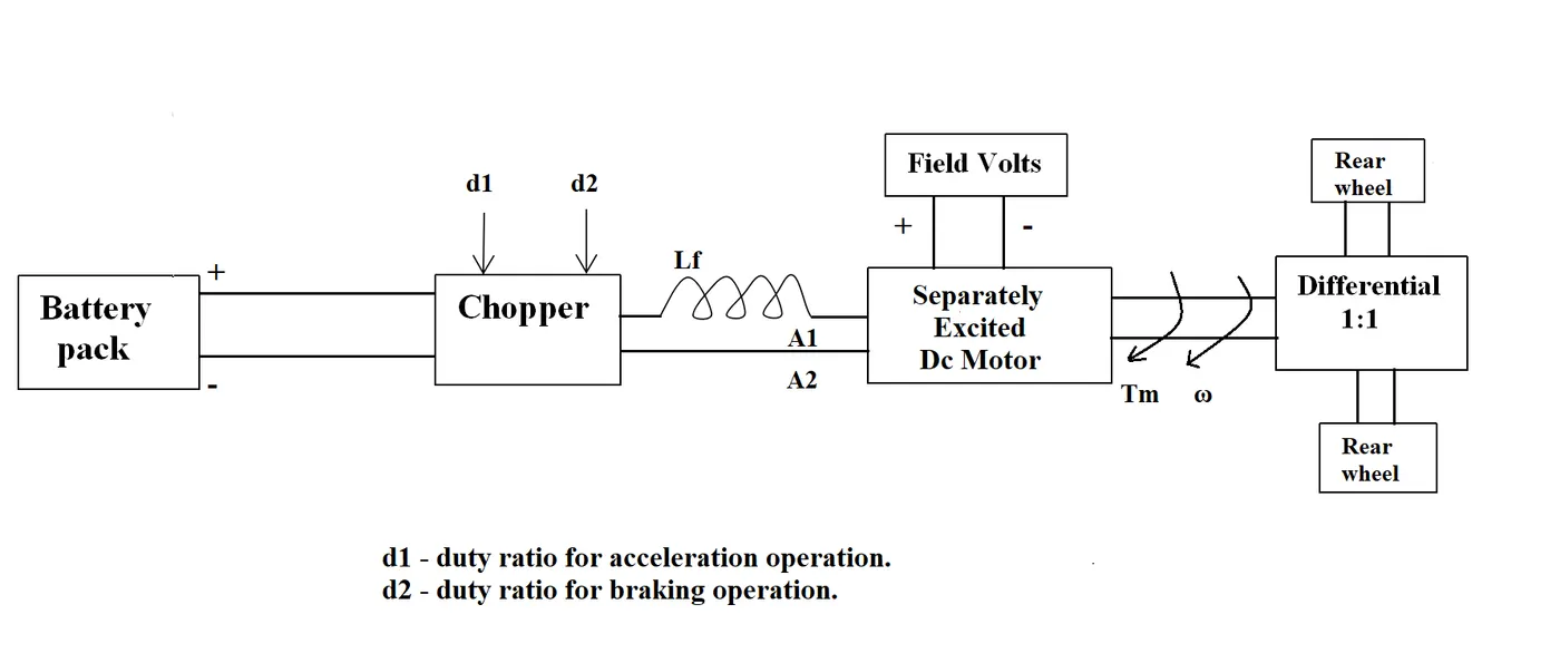
The other parameters of the electric vehicle is given below,
Motor and Controller Parameters:
Rated Armature voltage= 72 V
Rated armature current= 400 A
Ra= 0.5Ω, KΦ= 0.7 Volt second
Chopper Switching frequency= 400 Hz
The vehicle speed-torque characteristics are given by the below equation

What is EV steady state speed if duty cycle is 70%?
ANS:
Let's go through, what is given in the question. Let us assume, the `Tv` equation given is taken as equation No.1
Now, we know that,
`T=((K.V)/(Ra))-((K^2)/(Ra))*omega`.......................(eqn. 2)
Also,
`V=delta*Vb` => 50.4
now, substitute `V` in eqn 2 to get value for `T`. Now, we will get an equation for `T` in terms of `omega`. This can now be substituted in equation no 1 to get,
`70.56-0.98*omega=24.7+0.0051*omega^2`
Solving this, we will get two values for `omega`. One of them is a negative value, that needs to be discarded and we take the positive value, which is `omega` =38.91.
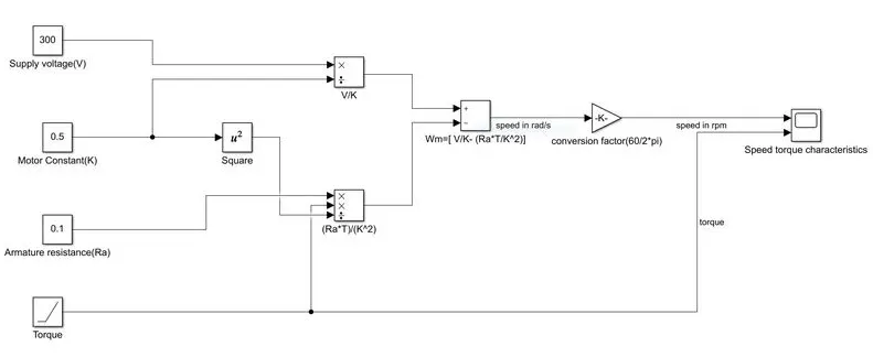
3.Develop a mathematical model of a DC Motor for the below equation using Simulink.
ωω= V/Kϕϕ -Ra/Kϕϕ^2 .T
MODEL:
RESULT: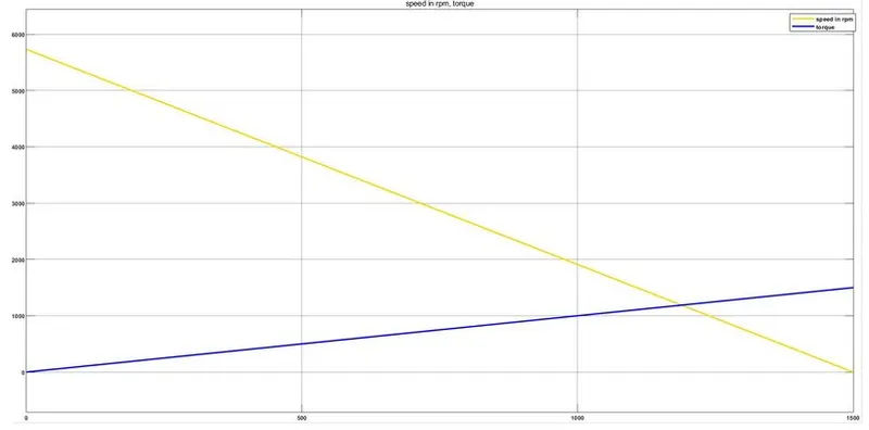
CONCLUSION: As we can observe from the characteristics that, as Torque increase, the speed decreases. This is in tandom with the equation.
4.Refer to the blog on below topic:
Induction Versus DC brushless motors by Wally Rippel, Tesla
Explain in brief about author’s perspective.
ANS:
Author's main aim here is to compare and contrast between Induction Motor (3-phase) and a DC Motor. First of all, he says, there is no perfect motor and the correct one is chosen based on the requirement.
1. One of the first point he metions is the Construction. Unlike the DC brushless rotor, the induction rotor has no magnets – just stacked steel laminations with buried peripheral conductors that form a “shorted structure.”
2. Starting Torque: 3-phase IM can start under load, while a DC source may need an inverter and timing circuit.
3. IM needs AC and torque performace improvements needs a feedback circuit to match the performance of a DC Motor
4. DC Motor, Rotor cooling is easier and peak point efficiency is generally higher for this drive.
5. DC Brushless has a better power factor.
6. Rotor losses in DC can be reduced with precise current control methods. But in 3 phase IM, since there is no magnets, it becomes difficult.
7. In DC machine, losses in propotional to its size, which is not desirable. IM does not have that issue.
Thus, no winner. But author also feels, both maybe used to-gether in future.
END