Final Project: Design of an Electric Vehicle
Create a MATLAB model of electric car which uses a battery and a DC motor. Choose suitable blocks from Powertrain block set. Prepare a report about your model including following:
Objectives:
1. System level configurations
2. Model parameters
3. Results
4. Conclusion
INTRODUCTION AND THEORY:
An electric vehicle (EV) is defined as a vehicle that uses an electric motor or a traction motor for propulsion as opposed to an internal combustion engine used by conventional vehicles. Electric vehicles use electricity for power instead of fossil fuels as conventional vehicles would and because of this difference, electric vehicles do not produce any exhaint gases or pollution. The power needed for the operation of an EV can come from a variety of sources such as batteses, generators, or through a collector system Batteries fitted in to the body of an EV are capable of high energy densities in order for them to meet the power demands and range requirements. Generations are machines which generate electrical energy from an input of mechanical work and are a part of the electric motor, and they operate during braking to produce the phenomenon of generative braking Collector systems are off-vehicle systems which allow for the changing of an EV from harmes or public charging stations. The electricity used for changing in these systems are generated from solar panels which can be used by the grid or by homes of EV owners so that they can charge their vehicles more conveniently
EVs are incasing in demand in recent years due to the need to reduce vehicle errsssions which are damaging to the environment Goverment incentives and private companies are working on schemes to quicken the adoption of electric vehicles. Since EVs do not produce any emissions, they are more envvonmentally friendly than conventional vehicles are. The generation of the electicty used to charge the vehicles also comes from solar energy (a renewable energy sources and not fosul fuels which makes them sustainable EVS can meet the same performance standarths of conventional vehicles and even surpass that of thers and this has been seen with the automotive company Tesla The Tesla Model 3 is the best selling EV in the world and is capable of a range of approximately 350km an single charge. It also has an accelmation of 0-40 mph in 56 seconds and a tup speed of 130 mph.
EVS offer several advantages over conventional vehicles beudes the lack of pollution and lack of need to mly on fossil fuels One is that, EVS are more efficient meaning that they offer more MPGe Imides per gallon gasoline equivalent), meaning that you will spend lesser on rechanging an
EV than you would to refurl a conventional vehicle. This because the more efficient the EVs, the more distance you travel with the avadable
energy in the US, Tesla owners can change their EVS for free at the private charging stations for life which results in significant savings in fuel
Regenerative beaking in EVs adds to the efficiency as the unsned energy in braking gets mused purposefully. Another benefit is that EVs have
fewer movinghotating parts and this means lesser maintmance costs than you would have with IC engine vehicles eg changing oil
transmeion flad This in the long term would gove better sevegs than you would get with conventional vehicles Lesser moving parts means
there is leser friction between moving parts and hence quieter operation
in spite of these feats, it will be difficialt for a worldende adoption of EVs for several masons. One mason is convenience in order for EVs to dominate the automotive market, ther needs to be more convenient ways for consumers to be able to charge the vehicles Ther needs to be several charging statears on the highways and roads and this can be supported if everyone's homes were generating solar power. It needs to be as easy to charge an EV as it is to an IC engine vehicle with fuel at a petrol stations Another reason is the cost of the EVs EVS are still a relatively new technology and only account for 2-3% of the worldwide market. This is because they most conudecabile more than conventional vehicles due to the high cast of batteries and electric components. But the cost of bameness getting cheaper over time and manufacturers are developing news and more efficient batteries. The goal is to produce a million mile battery which if made will be a revolution in the automotive sector. Another disadvantage is that the components in EVs operate at high voltages and cuments and thes can be a hazard if the components explode or dont weak as they should
A compmme between C engine wehicles and Evs exts as Hybnd Electrx Vefucles (HEV HEVs combine an IC engine with an electric propulsion system to produce a hybrid between the two different classes of vehicles. The purpose of this is to use the power available form the electric powertrain to improve the fuel economy of the vehicle so that it does not rely solely on the petrol/diesel it uses as fuel. This in turn will also improve the overall performance of the HEV.
There are two main types of electric vehicles (EV):
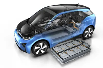
- Battery electric vehicles (BEV): The Battery electric vehicle uses only batteries for energy storage and must be plugged in to be recharged. Most current models of BEV do not store enough energy to provide a "normal" driving range and are limited to below 250 km (160 miles) per recharge. However, some new and forthcoming models offer substantially more range, up to 400 km. Recent on-going cost reductions of batteries have helped enable the growth of EV's.
- Plug-in hybrid electric vehicles (PHEV): The Plug-in hybrid electric vehicle has both batteries and liquid-fuel storage and refueling systems. PHEVs already offer 500 km or more due to the availability of their liquid-fuelled internal combustion engine. Both technologies are expensive, with battery costs estimated at around USD 350/kWh in 2015 and the cost of a hybrid system of several thousand dollars in PHEVS.
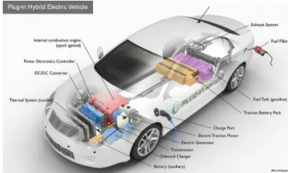
Components
The main components of a EV are:
- batteries
- power converters
- motor controllers
- motor/generator
- transmission system
- wheels/tires
Batteries store the electrical energy needed to power the EV in all of its systems and needs. Power converters convert the power coming from the battery to a usable form for the motor. This conversion can be from DC to AC or vice versa and can even be between 2 different magnitudes of DC to DC or AC to AC Motor controllers are electronics which control the amount of power delivered to the motor via control signals so that the motor is running as commanded. The motor is used for propulsion in order to move the vehicle in forward or reverse motoring. The generator is a part of the motor and just works in the opposite method to the motor. When braking, the vehicle can generate electricity and send this power back to the battery, charging it (regenerative braking). The transmission system is needed for the vehicle to change speeds as it accelerates/decelerates. The wheels are needed for traction on the roads and depending on the powertrain, the EV may be an FWD or RWD (forward or rear wheel drive). If a vehicle is an FWD, only the front axle wheels produce propulsion Le.. rotate from motor effect and if it is an RWD, the back axle wheels produce it instead. All wheel drives (AWDs) also exist where the front and rear axle wheels work together to produce propulsion.
System Level Configuration
To model an EV in SIMULINK, we will need to model the aforementioned components separately and then have them work together. All the main components are available in the library of SIMULINK blocks and we will be adding each component and configuring its parameters to fit the requirements of the model.
Let's start with the Driving Cycle
- Driving Cycle:
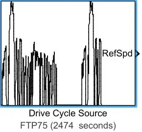
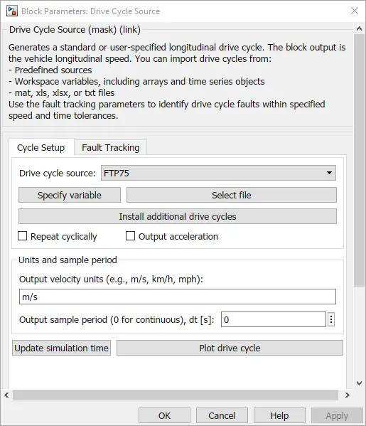
The Drive Cycle Source block generates a standard or user-specified longitudinal drive cycle. The block output is the specified vehicle longitudinal speed, which you can use to:
- Predict the engine torque and fuel consumption that a vehicle requires to achieve desired speed and acceleration for a givengear shift reference.
- Produce realistic velocity and shift references for closed-loop acceleration and braking commands for vehicle control and plant models.
- Study, tune, and optimize vehicle control, system performance, and system robustness over multiple drive cycles.
The plot for the FTP75 Drive Cycle Source is shown below.
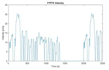
The Time in seconds at the x-axis and Velocity in meters per second at the y-axis. At which the plot shows the acceleration of the vehicle and deceleration of the vehicle for the period of 2474 seconds in which approx 41.2 minutes.
2. Longitudnal Driver
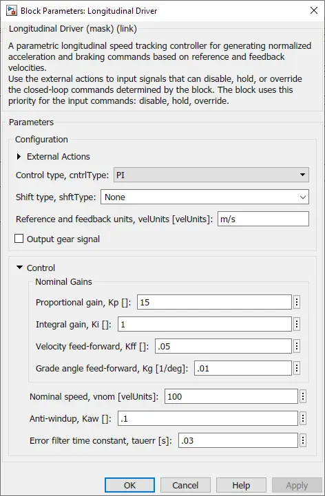
The Longitudinal Driver block implements a longitudinal speed-tracking controller. Based on reference and feedback velocities, the block generates normalized acceleration and braking commands that can vary from 0 through 1.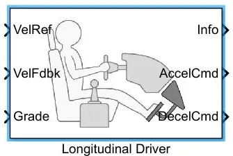
You can use the block to model the dynamic response of a driver or to generate the commands necessary to track a longitudinal drive cycle.
In the Longitudinal Driver block there some types of control type parameters to specify
- Pl: Proportional-Integral (PI) control with tracking windup and feed-forward gains
- Scheduled Pl: Pl control with tracking windup and feed-forward gains that are a function of vehicle velocity.
- Predictive:
Controller: Pl Speed-Tracking:
- The control type to Pl or scheduled Pl, the block implements proportional-integral (PI) control with tracking windup and feed forward gains. For the scheduled Pl configuration, the block uses feed-forward gains that are a function of vehicle velocity.
- To calculate the speed control output, the block uses these equations.
3. H-Bridge Controller:
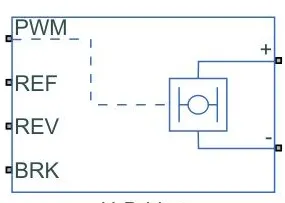
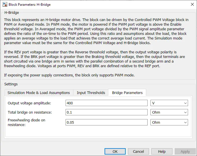
The H-Bridge block represents an H-Bridge motor driver. For H-Bridge it has Two different Power supply Internal and External. Now for this power supply, it goes with the Internal power supply. In Internal power supply, it deals with PWM.
The H-Bridge block output is a controlled voltage that depends on the input signal at the PWM port. If the input signal has a value greater than the Enable threshold voltage parameter value, the H-Bridge block output is on and has a value equal to the value of the Output voltage amplitude parameter. if it has a value less than the Enable threshold voltage parameter value.
The block maintains the load circuit using one of the following three Freewheeling modes Options:
- One semiconductor switch and One freewheeling diode
- Two freewheeling diode
- Two semiconductor switches and One freewheeling diode
The signal at the REV port determines the polarity of the output.
If the value of the signal at the REV port is less than the Reverse threshold voltage parameter value, the output has positive polarity.
if the value of the signal at the REV port is higher than the Reverse threshold voltage parameter value, the output has negative polarity.
Braking mode is invoked when the voltage presented at the BRK port is larger than the Braking threshold voltage.
4. Controlled PWM Voltage:
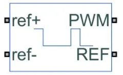
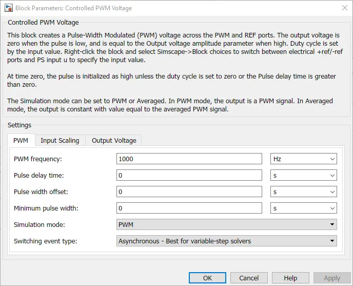
The Controlled PWM Voltage block represents a pulse-width modulated (PWM) voltage source. This block has two modeling
variants, accessible by right-clicking the block in your block diagram and then selecting the appropriate option from the
context menu, under Simscape - Block choices:
Electrical input ports: The block calculates the duty cycle based on the reference voltage across its ref+ and ref-ports. This modeling variant is the default.
PS input: Specify the duty cycle value directly by using an input physical signal port.
Here in Controlled PWM Voltage, it goes with Electrical input ports for this modeling.
For Electrical input ports The variant of this block the demanded Duty cycle is `(V_(ref)-V_(min))/(V_(max) V_(min))100%`
where,
`V_(ref)` is the reference voltage across the ref+ and ref- ports.
`V_(min)` is the minimum reference voltage.
`V_(max)` is the maximum reference voltage.
Use a fixed-step or local solver and the discrete-time switching event type we going to use. So we can use the SOLVER CONFIGURATION block to calculate all the multiple simulation step sizes.
5. Battery:
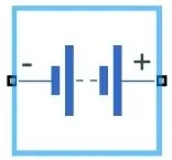
The Battery block represents a simple battery model. This block has four modeling variants which are:
- Uninstrumented | No thermal port: The basic model does not output battery charge level or simulates thermal effects and also this modeling variant is the default.
- Uninstrumented | Show thermal port:The model with an exposed thermal port and also this model does not measure the internal charge level of the battery.
- Instrumented | No thermal port:The model with an exposed charge output port and also this model does not simulate thermal effects.
- Instrumented | Show thermal port: The model lets you measure the internal charge level of the battery and simulate thermal effects with both the thermal port and the charge output port are exposed.
This Battery block represents the energy source for the electric vehicle.
If by selecting Infinite for the battery charge capacity parameters, the block models the battery as a series internal resistance and a constant voltage source.
If by selecting Finite for the Battery charge capacity parameter, the block models the battery as a series internal resistance plus a charge dependent voltage source will be defined by
`V-(V_(nom) SOC)/(1-beta (1-SOC)`
6. DC Motor:
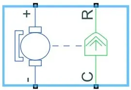
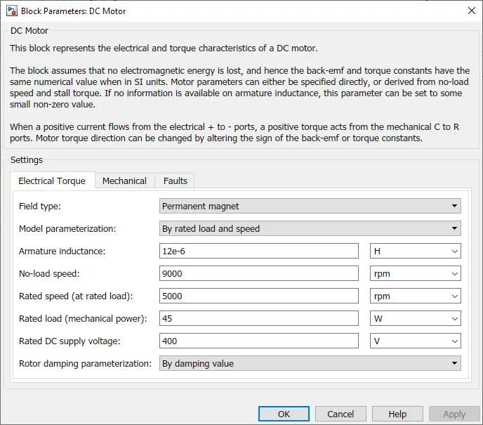
The DC Motor block represents the electrical and torque characteristics of a DC Motor.
This DC motor block assumes that no electromagnetic energy is lost, and hence the back-emf and torque constants have the same numerical value when in Sl units. Motor parameters can either be specified directly or derived from the no-load speed and small torque. If no information is available on the armature, Inductance, these parameters can be set to some small non-Zero values.
When a positive current flows from the electrical to-ports, a positive torque acts from the mechanical C to R ports. Motor torque can be changed by altering the sign of the back-emf or torque constants.
7. Vehicle Modelling:
Tyre: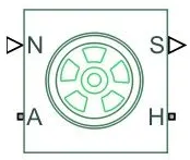
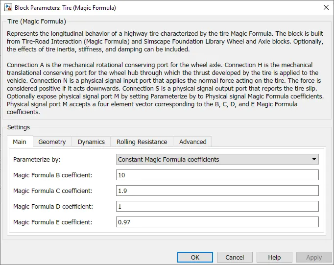
This Tire block Represents the longitudinal behavior of a highway Tire characterized by the tire Magic Formula. The block is built from Tire-Road Interaction (Magic Formula) and Simscape Foundation Library Wheel and Axle blocks. Optionally, the effects of tire inertia, stiffness, and damping can be included.
Connection A is the mechanical rotational conserving port for the wheel axle. Connection H is the mechanical translational conserving port for the wheel hub through which the thrust developed by the tire is applied to the vehicle. Connection N is a physical signal input port that applies the normal force acting on the tire. The force is considered positive if it acts downwards. Connection S is a physical signal output port that reports the tire slip. Optionally physical signal port M by setting Parameterize by to Physical signal Magic Formula coefficients. Physical signal port M accepts a four-element vector corresponding to the B,C,D and E Magic Formula Coefficients.
Simple Gear:
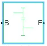
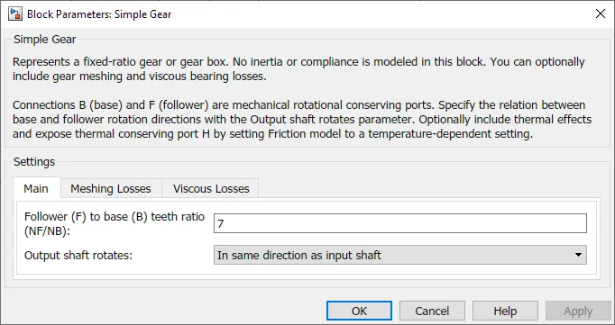
This block represents a fixed-ratio gear or gearbox. No inertia or compliance is modeled in this block. You can optionally include gear meshing and viscous bearing losses.
Connections B (base) and F (follower) are mechanical rotational conserving ports. Specify the relation between base and follower rotation directions with the Output shaft rotates parameter. Optionally thermal effects include and expose thermal conserving port H by right-clicking on the block and selecting Simscape block choices to switch between variants.
Vehicle Body:
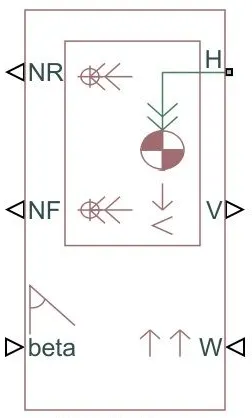
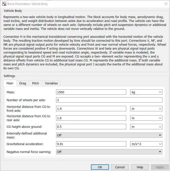
This block represents a two-axle vehicle body in longitudinal motion. The block accounts for Body mass, Aerodynamic drag. Road incline, and Weight distribution between axles due to acceleration and Road profile. The vehicle can have the same or a different number of wheels on each axle. Optionally pitch includes and suspension dynamics or additional variable massand inertia.
The vehicle does not move vertically relative to the ground.
- Connection H is the mechanical translational conserving port associated with the horizontal motion of the vehicle body.The resulting traction motion developed by tires should be connected to this port.
- Connections V are physical signal output ports for vehicle velocity
- Connections NF and NR are physical signal output ports for front and rear normal wheel forces, respectively.
- Connections W and beta are physical signal input ports corresponding to headwind speed and road inclination angle, respectively.
Wheel forces are considered positive if acting downwards.
If the variable mass is modeled, the physical signal input ports CG and M are exposed. CG accepts a two-element vector representing the x and y distance offsets from vehicle CG to additional load mass CG. M represents the additional mass.
If both variable mass and pitch dynamics are included, the physical signal port J accepts the inertia of the additional mass about its own CG.
Model Design of Electric Vehicle
SIMULINK MODEL OF EV:
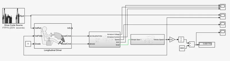
The Electric vehicle (EV) is constructed in a manner of FOUR step by step processes. So to design the EV model always starts
within the order
1. Construction Of Vehicle Body Design.
2. Construction Of Motor or Engine/ Selecting Of Motor or Engine.
3. Suitable Control Unit For Motor or Engine.
4. Source of Energy for Motor or Engine.
Let's start with step-1: Construction Of Vehicle Body Design.
- The construction of vehicle body design mainly depends upon The vehicle Body block, Tire block, Simple Gear block, DC Motor (Mechanical Rotar side) block and Longitudinal Driver block
Tire connection to vehicle body: Basically, a car has four wheels. It is constructed in a way of Two wheels at the Front side and Two wheels at the Rare side
- Each Tire consists of an H-port which is a wheel Hub, A-port which is a wheel Axle, and N-port which is a Normal force.
- The Tire 1& Tire 2 are Front Tire systems and The Tire 3 & Tire 4 are Rare Tire system
- The Front Tire system
- From Tire 1 block and Tire 2 block, the ports of Wheel Axle A1 are connected to Wheel Axle A2, and this intersection point is connected to the Follower(F) from Simple Gear
- From Tire 1 block and Tire 2 block, the part of Wheel Hub H1 is connected to Wheel Hub H2, and this intersection point is connected to the Hub (H) of the Vehicle Body
- From Tire 1 block and Tire 2 block. The port of Normal Force N1 is connected to Normal Force N2, and this intersection point is connected to Normal Front Force (NF) of the Vehicle Body.
- From Tire 1 block and Tire 2 block, The Slip of the Tire is Neglected.
- The Rare Tire system
- From Tire 3 block and Tire 4 block, the ports of Wheel Axle A3 are connected to Wheel Axle A4.
- From Tire 3 block and Tire 4 block, the port of Wheel Hub H3 is connected to Wheel Hub H4, and this intersection point is connected to the Hub (H) of the Vehicle Body.
- From Tire 3 block and Tire 4 block. The port of Normnal Force N3 is connected to Normal Force N4, and this intersection point is connected to Normal Rare Force (NR) of the Vehicle Body.
- From Tire 3 block and Tire 4 block. The Slip of the Tire is Neglected.
• Vehicle Body connection to Longitudinal Driver.
The Vehicle Body Velocity (V) is connected directly Feedback to The Longitudinal Vehicle Velocity (VelFdbk)
Step-2: Construction Of Motor/Selecting Of Motor.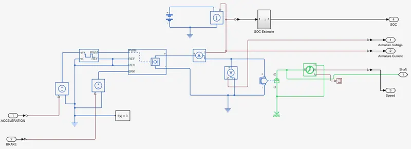
Selecting of Motor is taken as DC Motor:
The Motor system mainly depends upon DC Motor, Ideal Rotational Motion Sensor, H-Bridge controller, and CurrentSensor.
The DC MOTOR is connected to Ideal Rotational Motion Sensor to find the RPM of the vehicle's speed.
The DC Motor has Two systems
- Electrical system:
- The Electrical system has two ports, a Positive (+) port and a Negative (-) Port
- The DC Motor Positive(+) port is connected to the Current Sensor of Negative(-) port
- The DC Motor Negative(-) port is connected to H-Bridge Negative(-) port and these two signals ports are connected through the Electrical Reference
- Mechanical System:
- The Mechanical system has two ports, Motor Caseing (C) port and Motor Rotor (R) Port
- The DC Motor of Motor Caseing (C) port is connected to the Motor Caseing (C) port of Ideal Rotational Motion
- Sensor and these two signals ports are connected through Mechanical Rotational Reference
- The DC Motor of Motor Rotor (R) port is connected to the Motor Rotor (R) port of Ideal Rotational Motion Sensor and this intersection point is connected to the Base (8) port Of the Simple Gear.
step-3: Suitable Control Unit For Motor
The Suitable Control Unit For Motor mainly consists of an H-Bridge controller, Controlled PWM Voltage, Controlled Voltage Source. Longitudinal Driver, and Driving Cycle Source
- H-Bridge Controller To DC Motor
- The DC Motor Positive(-) port is connected to the Current Sensor of Negative(-) port and the Current Sensor of Positive (+) port is connected to the Positive(+) port of the H-Bridge
- The DC Motor Negative(-) port is connected to H-Bridge Negative(-) port and these two signals ports are connected through the Electrical Reference.
- H-bridge Motor drive To Controlled PWM Voltage:
- H-Bridge drive has PWM port, REF port which is ZERO VOLT REFERENCE. REV port which is REVERSE, and BRK port which is BREAKING.
- Controlled PWM Voltage has PWM port, REF port which is ZERO VOLT REFERENCE. (ref.) port is Positive Terminal, and (ref-) port is Negative Terminal.
- Connections OF H-Bridge and Controlled PWM Voltage
- The H-Bridge PWM port is connected directly to the PWM port of the Controlled PWM Voltage
- The H-Bridge REF port is connected directly to the REF port of the Controlled PWM Voltage and there is an interconnection between the REV port of the H-Bridge.
- The H-Bridge REV port is connected to Solver Configuration and Electrical Reference
- The H-Bridge BRK port is connected to the Positive (+) port of the controller voltage Source 1 and the controller voltage Source 1 of the Negative(-) port is connected to the Electrical Reference Junction point.
- The Controlled PWM Voltage ref+ port is connected to the Controlled Voltage Source Positive(+) and Negative (-) port of the Controlled PWM Voltage connected to the ref-port of the Controlled PWM Voltage and interconnection through the Electrical Reference Junction point.
- Longitudinal Driver Command Connected to Controlled Voltage sources:
Longitudinal Driver Consists of VelRef port which is Vehicle Reference, VelFbdk port which is Vehicle Feedback Reference, Grade port which is Gradiante percentage. AccelCmd port which is Acceleration Command, and DecelCmd port which is Deceleration Command
-
Acceleration Command:
The AccelCmd port of the Longitudinal drive of the Physical system is connected to the Physical system of the Controlled Voltage source for the Acceleration Motion or Forward Movement of the vehicle.
-
Deceleration Command:
The DecelCmd part of the Longitudinal drive of the Physical system is connected to the Physical system of Controlled Voltage source-1 for the Breaking the Vehicle or Deceleration of the vehicle
-
The Driving Cycle 5 ource output velocity is directly connected to the VelRef port of Longitudinal Driver, which is Vehicle Reference input source Velocity values
-
step-4: Source of Energy for Motor
- The Source of Energy for Motor is BATTERY Power supply of 300 volts. The power supply is directly connected to DC Motor through Controlled Current Source and Current Sensor of the DC Motor
- In Battery System, It consists of Battery, Controlled current Source, and State Of Charge Estimation Calculation the Battery system.
- In the Battery system, The current is controlled through a Controlled current Source at which how much the amps flow in the battery system.
SIMULINK MODEL OF VEHICLE BODY SUBSYSTEM: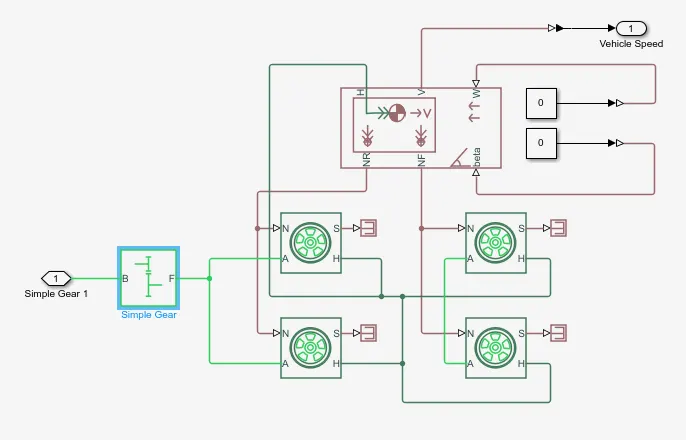
The construction of vehicle body design mainly depends upon The vehicle Body block, Tire block, Simple Gear block, DC Motor (Mechanical Rotar side) block, and Longitudinal Driver block.
Tire connection to vehicle body:
- Basically, a car has four wheels. It is constructed in a way of Two wheels at the Front side and Two wheels at the Rare side.
- Each Tire consists of an H-port which is a wheel Hub, A-port which is a wheel Axle, and N-port which is a Normal force.
- The Tire 1 & Tire 2 are Front Tire systems and The Tire 3 & Tire 4 are Rare Tire system.
- The Front Tire system
- From Tire 1 block and Tire 2 block, the ports of Wheel Axle A1 are connected to Wheel Axle A2, and this intersection point is connected to the Follower(F) from Simple Gear.
- From Tire 1 block and Tire 2 block, the port of Wheel Hub H1 is connected to Wheel Hub H2, and this intersection point is connected to the Hub (H) of the Vehicle Body.
- From Tire 1 block and Tire 2 block. The port of Normal Force N1 is connected to Normal Force N2, and this intersection point is connected to Normal Front Force (NF) of the Vehicle Body.
- From Tire 1 block and Tire 2 block, The Slip of the Tire is Neglected.
- The Rare Tire system
- From Tire 3 block and Tire 4 block, the ports of Wheel Axle A3 are connected to Wheel Axle A4.
- From Tire 3 block and Tire 4 block, the port of Wheel Hub H3 is connected to Wheel Hub H4, and this intersection point is connected to the Hub (H) of the Vehicle Body.
- From Tire 3 block and Tire 4 block. The port of Normal Force N3 is connected to Normal Force N4, and this intersection point is connected to Normal Rare Force (NR) of the Vehicle Body.
- From Tire 3 block and Tire 4 block. The Slip of the Tire is Neglected
Vehicle Body connection to Longitudinal Driver:
- The Vehicle Body Velocity (V) is connected directly Feedback to The Longitudinal Vehicle Velocity (VelFdbk)
- The Simple Gear Port B (base) is connected to the DC Motor port of Mechanical Rotor (R)
SIMULINK MODEL of State of Charge Estimation Subsystem: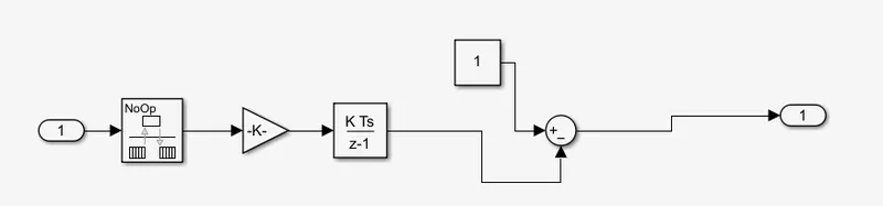
In Battery System, It consists of Battery, Controlled current Source, and State Of Charge Estimation Calculation
In the Battery system. The current is controlled through a Controlled current Source at which how much the amps flow in the Battery system.
The Value of Current Sensor (I) is Integrated to the value of Gain of 1/(80*3600) is subtracted from 1, where 80 is amps, 3600 is time (t)
The SOC Calculated by `SOC-[(int(1/(amp*t)))-1]`
Distance Calculation:
MODEL PARAMETERS for Components
- Driving Cycle:
- Longitudional driver block
- Controlled PWM Voltage
- H-Bridge Converter
- Battery
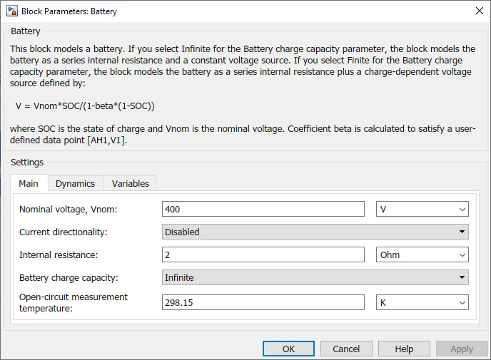
- DC Motor:
- Vehicle Body:
- Gear:
- Tire:
Model Working:
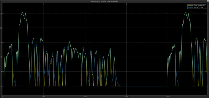
- Initially the velocity data with respect to time from drive cycle FTP75 given as referance to longitudinal drive "velref" input.
- The driver feedback velocity input is given as speed from vehicle body output. It compare both the velocities.give output pulses as acceleration and deceleration commands.
- In the model let as assume no slope is present on ground surface, vehicle moves in flat surface as grade given as 0. The main condition in this block is the drive sycle referance speed and feedback speed should be in same unit for comparing using Pl controller.
- The acceleration and deceleration commands are in simulink signals.So we have to convert to physical signals using Simulink-PS converters.
- The converted physical signals are given as input variable signals to controlled voltage sources for inputs to controlled PWM signal block and break input to H-bridge.
- The acceleration Voltage source values are given to controlled voltaage source and given to PWM port of H-bridge.
- The deceleration voltage source is directly conected to break port of H-bridge.
- All referance ports are grounded with electrical referance.Here in the drive cycle we are not reversing the vehicle.so rev port also connected to electrical referance.
- In H-bridge circuit the input power supply source from battery is given as internal power supply mode as voltage assigned as rated voltage output of H-bridge. The output of H-bridge connected to a DC brush type motor terminals through current sensor block for measuring armature current of motor. A voitage sensor is connected across two terminals of motor for measuring armature voltage of motor.
- Here the motor is rated as 400V and rated load capacity as 45KW. No-load rpm as 9000rpm and rated rpm at rated load as 5000rpm. The motortype is selected as permanent magnet.
- The mechanical output through the shaft is coupled with the axle of vehicle body through a simple gear A ideal rotational motion sensor is connectes across R and C ports of Shaft to find the angular speed of motor shaft
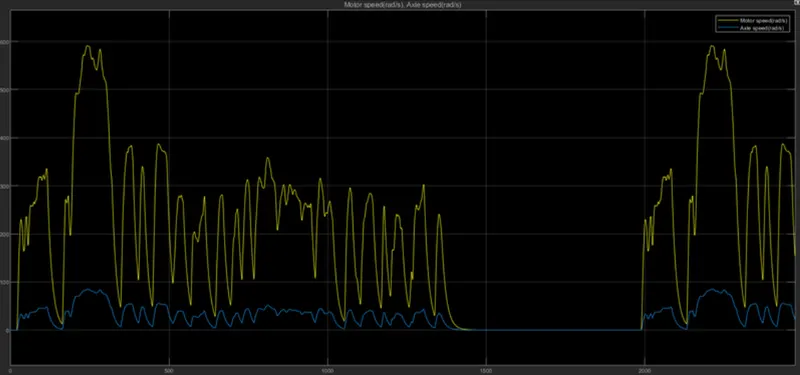
- In vehicle body, the simple gear ratio is given as 7 for our model. Which means & times the base speed equals the follower speed. Here base speed as motor shaft speed and follower speed as Axle speed.
- Tire parameters are configured for front and rear wheels. The forces for both front and rear wheels are connected through NR.NF ports All H ports of wheels are connected to hub of vehicle body.
- All S (slip) ports of wheels are connected to ps-terminator blocks as no slips are considered in our model. The grade angle and wind drag values. are given through W,beta ports
- The output velocity of vehicle can be viewed by V port.
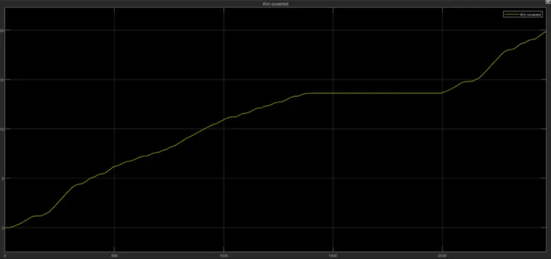
- For finding the distance travelled by the vehicle the speed value multiplied by 3.6 for Kmph and then integrated. The integrated values are divided by 3600 for converting to distance travelled in per second.
- The vehicle velocity output given as feedback to longitudinal driver for comparison with referance drive cycle speed. . For every second the vehicle velocity is compared with referance drive cycle velocity, based on that vehicle speed is controlled.
PLOTS:
Drive Cycle vs Vehicle Speed.
Distance covered.
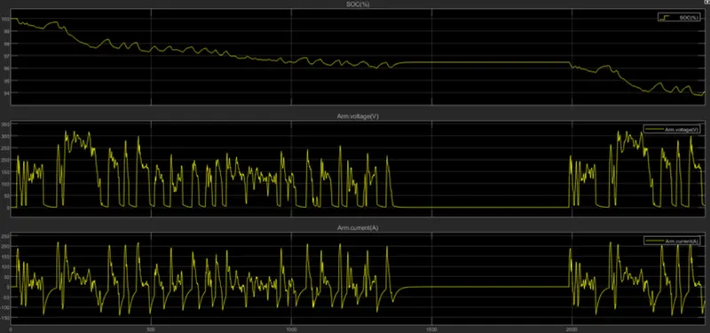
Battery SOC, Armature Voltage and Current
Motor Speed vs Axle Speed
CONCLUSION:
From the above results we justified that,
- The vehicle velocities is controlled with drive cycle velocities.
- The Soc of battery charged during deceleration periods and discharges during acceleration period.
- For this drive cycle the the charge reduced to 94% from 100% for the distance covered of 19.84 Kms.
- The motor shaft rpm is 7 times of axle side rpm.
- The armature current are in +positive direction when accelerating and in-negative direction during deceleration as it charging the battery.
- The armature voltages varies accordingly to switching pulses from H-bridge.
- We can also change the motor ratings accordingly with gear ratios to increase the vehicle ranges.