Project
AIM:
To prepare a detailed technical report on BAJA All-Terrain Vehicle (ATV) simulation under varying conditions.
OBJECTIVES:
Conduct a system level simulation under varying parameters and inputs and prepare a technical report as well as observe and study the various outputs.
THEORY:
- All Terrain Vehicle (ATV):
ATV's are vehicles that travels on low-pressure tires which also has a seat designed to be straddled by the operator and handlebars for steering control. They are mainly used for off-highways.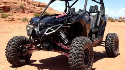
- Continously Variable Trasnmission Drive (CVT):
These are a type of transmission where mostly have a pair of variable-diameter, cone-shaped pulleys connected by a steel or composite belt. The one half of each pulley is fixed and the other side is movable which is actuated by a hydraulic cylinder. This cylinder can increase or decrease the amount of space between them. This helps to make a gear-like setup. The process is illustrated in the given image below.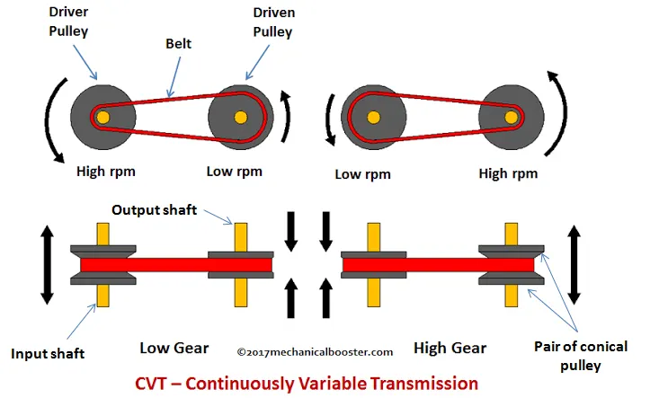
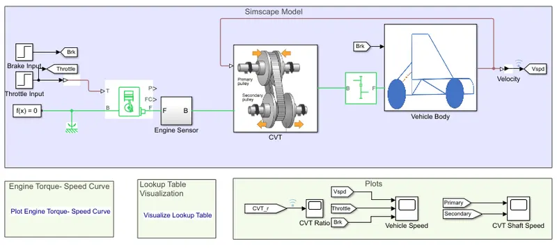
1. SIMULATION MODEL 1 -Using BAJA ATV with a pre-defined CVT Ratio as input.
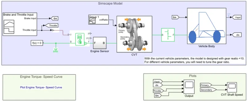
Important blocks in the above model:
- Continously Variable Transmission (CVT) Block
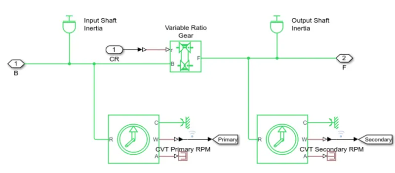
- Variable Gear Ratio: Represents a variable ratio gearbox such as implemented by mechanical belt CVT, electric, or hydraulic transmissions. The physical signal input r defines the ratio of input to output angular shaft velocities. Connections B (base) and F (follower) are mechanical rotational conserving ports. Specify the relation between base and follower rotation directions with the Output shaft rotates parameter.
- Ideal Rotational Motion Sensor: This block measures angular velocity or angle in a mechanical rotational network. The sensor is ideal since it does not account for inertia, friction, delays, energy consumption, and so on.
- Variable Gear Ratio: Represents a variable ratio gearbox such as implemented by mechanical belt CVT, electric, or hydraulic transmissions. The physical signal input r defines the ratio of input to output angular shaft velocities. Connections B (base) and F (follower) are mechanical rotational conserving ports. Specify the relation between base and follower rotation directions with the Output shaft rotates parameter.
- Engine Block:
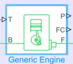
Represents a system-level model of spark-ignition and diesel engines suitable for use at initial stages of modeling when only the basic parameters are available. Optional idle speed and red line controllers are included.The throttle input signal T lies between zero and one and specifies the torque demanded from the engine as a fraction of the maximum possible torque. Connections F and B are mechanical rotational conserving ports associated with the engine crankshaft and engine block, respectively. Connections P and FC are physical signal output ports through which engine power and fuel consumption rate are reported.
- Brake and Throttle Input:
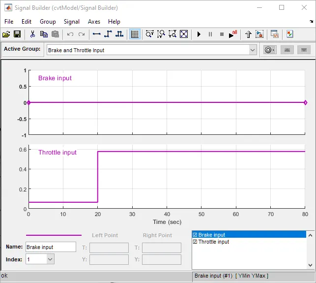
We here use a signal builder to create a customer throttle and brake input. - CVT Gear Ration Input:
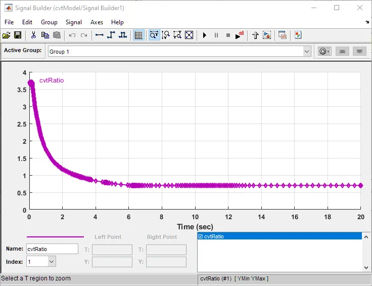
- Engine Torque-Speed Input:
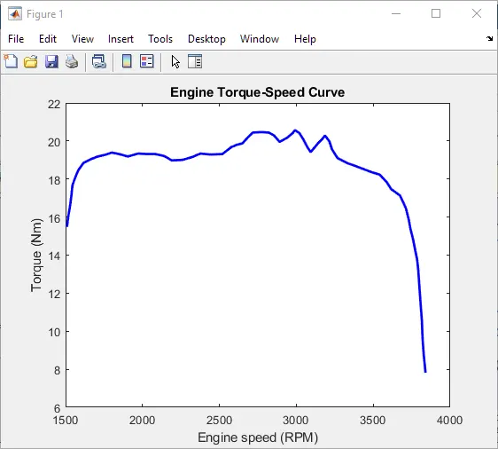
- Vehicle Body:
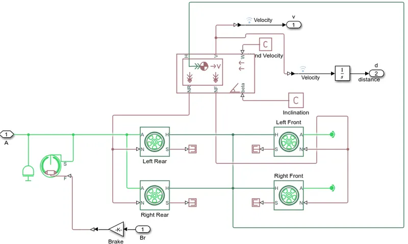
This Block contains,
- Vehicle Body block: Represents a two-axle vehicle body in longitudinal motion. The block accounts for body mass, aerodynamic drag, road incline, and weight distribution between axles due to acceleration and road profile.
- Tire: Represents the longitudinal behavior of a highway tire characterized by the tire Magic Formula. The block is built from Tire-Road Interaction (Magic Formula) and Simscape Foundation Library Wheel and Axle blocks.
- Double Shoe Brake: Represents a brake arranged as two pivoted rigid shoes symmetrically installed inside or outside a drum and operated by one actuator. The actuator force causes the shoes to exert a friction torque on a shaft connected to the drum.
- Vehicle Body block: Represents a two-axle vehicle body in longitudinal motion. The block accounts for body mass, aerodynamic drag, road incline, and weight distribution between axles due to acceleration and road profile.
- Simple Gear:

Represents a fixed-ratio gear or gear box. No inertia or compliance is modeled in this block. You can optionally include gear meshing and viscous bearing losses.Connections B (base) and F (follower) are mechanical rotational conserving ports. Specify the relation between base and follower rotation directions with the Output shaft rotates parameter.
OBSERVATION AND RESULT FOR SIMULATION 1 -Using BAJA ATV with a pre-defined CVT Ratio as input.
- Vehicle Speed and Throttle Brake Inputs
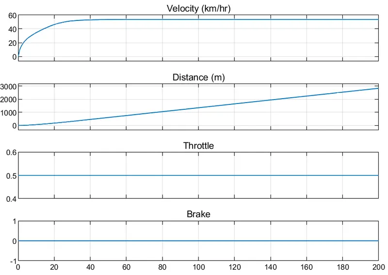
Here, we can see, the vehicle reaches it's maximum speed - 53.5 Km/h after 90 secs. The distance travelled by then is around 1,200m. We haven't applied any brakes in this scenario. From this, we can understad the top speed and the acceleration of the vehicle for the given input throttle levels. - CVT Shaft Speed:
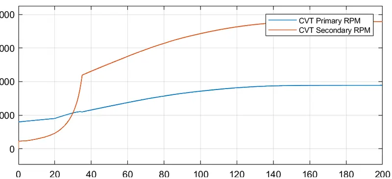
We can see the RPMs of both the Primary and Secondary shafts here. The trend is similar to the vehicle velocity graph. The given levels are for the fixed gear ratio in the Gear ratio block.
2. SIMULATION MODEL 2 -Using BAJA ATV with CVT using Dashboard.
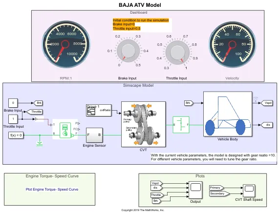
In this model, all the items are similar from model 1 apart from the introduction of the Dashboard. The Dashboard contains knobs to control the input values like "throttle" and "brake". This is useful such in cases where the user wants to change values during the simulation run time.
OBSERVATION AND RESULT FOR SIMULATION 2-Using BAJA ATV with CVT using Dashboard.
- Vehicle Speed and Throttle Brake Inputs
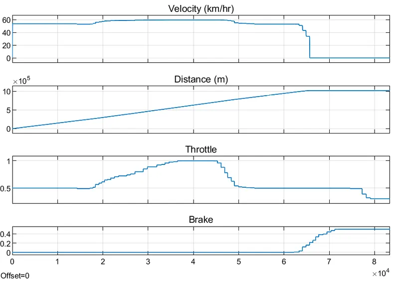
Here with the starting condition of Throttle at 0.5 and Brake at 0. The car accelerates towards 50 km/h and then when we increase the throttle, the speed increases again close to 60 km/h untill the throttle is reduced brakes are applied, which brings back the car to an halt. - CVT Shaft Speed:
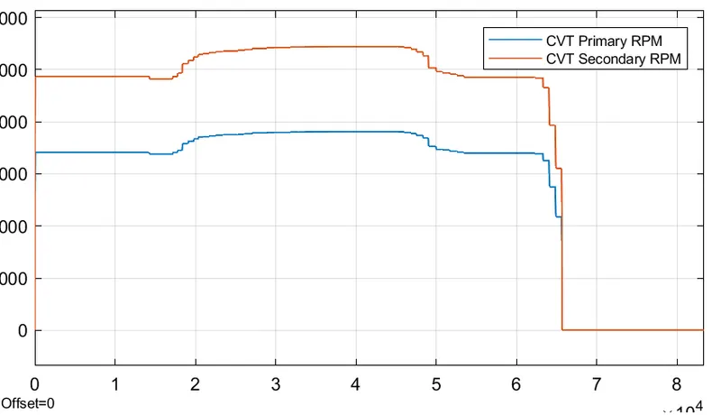
3. SIMULATION MODEL 3 -Using BAJA ATV with CVT using Lookup Table
CVT Block: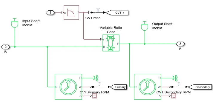
In this model, the only difference from previous is that we are giving the 'Gear Ration' input is given to the CVT through a lookup table. Rest of the parameters like vehicle velocity and shaft rpm outputs remain the same.
LookUp Table: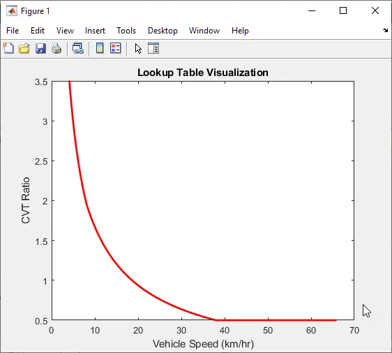
CVT Ratio Input from LUT: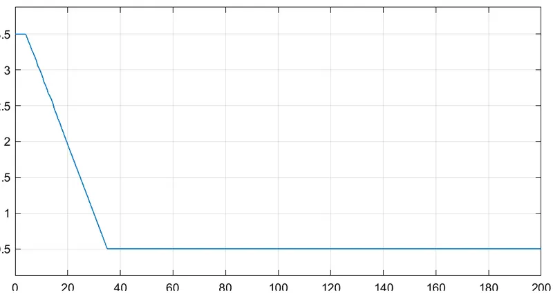
OBSERVATION AND RESULT FOR SIMULATION 3 - Using BAJA ATV with CVT using Lookup Table
- Vehicle Speed with Throttle, Brake:
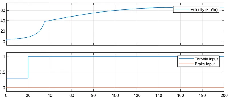
- CVT Shaft Speed:
Here, we will have similar results as in Case 1, as we are keeping same input parameters.
4. SIMULATION MODEL 4: Using BAJA ATV with CVT using Lookup Table and Dashboard
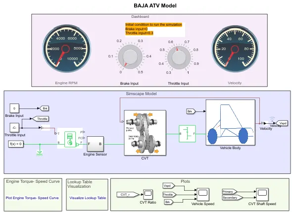
OBSERVATION AND RESULT FOR SIMULATION 4 - Using BAJA ATV with CVT using Lookup Table and Dashboard
- Vehicle Speed with Throttle, Brake:
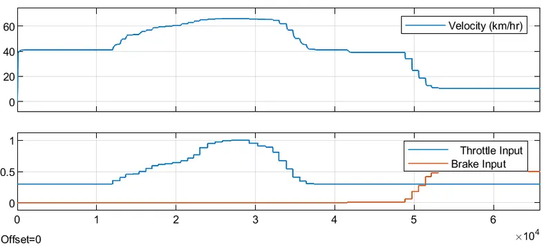
Same results as in Case 2. However we have chosen random throttle and brake application. But the relations betereen the velocity and brake, Throttle remains the same for different data points. - CVT Shaft Speed:
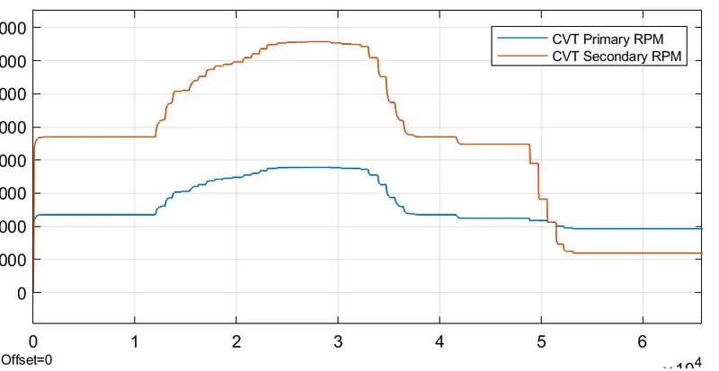
Same as Case 2.
RESULT: The simulation model of the "BAJA ATV Vehicle with CVT" was carried out for 4 different models that different on input types (Brake, Throttle & CVT Ratio). For all 4 cases the respective outputs "Vehicle Velocity and CVT Shaft RPM" were observed and studied.