Project-1: Powertrain for aircraft in runways
PART A:
1. Search and list out the total weight of various types of aircrafts.
1. Aircraft Total Weight:
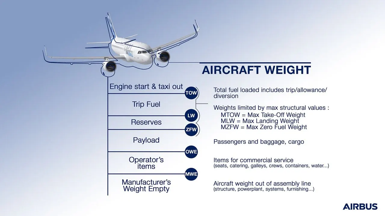
- The aircraft gross weight is also known as the All-up weight and abbreviated AUW is the total weight at any moment during the flight or ground operation. An aircraft's gross weight will decrease during a flight due to fuel and oil consumption. An aircraft's gross weight may also vary during flight due to payload dropping or In-flight refueling.
- At the moment of releasing its brakes, the gross weight of an aircraft is equal to its takeoff weight. during flight, an aircraft,s gross weight is referred to as the en-route weight or in-flight weight.
2. Structural Design Weights
- An aircraft's gross weight is limited by several weight restrictions to avoid overloading its structure or to avoid unacceptable performance or handling qualities while in operation.
- The absolute maximum weight capabilities of a given aircraft are referred to as the structural weight limits. The structural weight limits are based on aircraft maximum structural capability and define the envelope for the CG charts.
- An aircraft's structural weight capability is typically a function of when the aircraft was manufactured, and in some cases, old aircraft can have their structural weight capability increased by structural modifications.
- Maximum Design Taxi Weight
- The maximum design taxi weight is also known as the maximum design ramp weight (MDRW) is the maximum weight certificated for aircraft maneuvering on the ground (taxiing or towing) as limited by aircraft strength and airworthiness requirements.
- The maximum design taxi weight is also known as the maximum design ramp weight (MDRW) is the maximum weight certificated for aircraft maneuvering on the ground (taxiing or towing) as limited by aircraft strength and airworthiness requirements.
- Maximum Design Takeoff Weight
- The maximum design takeoff weight is the maximum certificated design weight when the brakes are released for takeoff and they are the greatest weight for which compliance with the relevant structural and engineering requirements has been demonstrated by the manufacturer.
-
Maximum Design Landing Weight
-
The maximum certificated design weight at which the aircraft meets the appropriate landing certification requirements. It generally depends on the landing gear strength or the landing impact loads on certain parts of the wing structure.
-
The maximum landing weight is typically designed for 10 feet per second (600 feet per minute) sink rate at touch down with no structural damage.
-
The maximum design landing weight (MDLW) must not exceed the maximum design takeoff weight (MDTOW).
-
- Maximum Design Zero Fuel Weight
- The maximum certificated design weight of the aircraft less all usable fuel and other specified usable agents (engine injection fluid, and other consumable propulsion agents). It is the maximum weight permitted before usable fuel and other specified usable fluids are loaded in specified sections of the airplane.
- The maximum design zero fueling weight (MDZFW) is limited by strength and airworthiness requirements. The subsequent addition of fuel will not result in the aircraft design strength being exceeded at this weight.
- The weight difference between the maximum design takeoff weight (MDTOW) and the maximum design zero fueling weight (MDZFW) may be utilized only for the addition of fuel.
- Maximum Flight Weight
- Minimum certificated weight for flight as limited by aircraft strength and airworthiness requirements.
Weights of commonly known Aircrafts:
|
Type |
MTOW [kg] |
MLW [tonnes] |
|
Airbus A380-800 |
575,000 |
394 |
|
Boeing 747-8F |
447,700 |
346.091 |
|
Boeing 747-8 |
443,613 |
306.175 |
|
Boeing 747-400ER |
412,770 |
295.742 |
|
Boeing 747-400 |
396,900 |
295.742 |
|
Boeing 747-200 |
377,840 |
285.700 |
|
Boeing 747-300 |
377,840 |
260.320 |
|
Airbus A340-500 |
371,950 |
240 |
|
Airbus A340-600 |
367,400 |
256 |
|
Boeing 777F |
347,800 |
260.816 |
|
Airbus A330-900 |
352,000 |
251.5 |
|
Boeing 777-300ER |
351,800 |
251.29 |
|
Boeing 777-200LR |
347,450 |
223.168 |
|
Boeing 747-100 |
340,200 |
265.300 |
|
Airbus A350-1000 |
308,000 |
233.5 |
|
Boeing 777-300 |
299,370 |
237.683 |
|
Boeing 777-200ER |
297,550 |
213.00 |
|
Airbus A340-300 |
276,700 |
190 |
|
McDonnell Douglas MD-11 |
273,300 |
185 |
|
Airbus A350-900 |
270,000 |
175 |
|
Ilyushin Il-96M |
270,000 |
195.04 |
|
McDonnell Douglas DC-10 |
256,280 |
183 |
|
Boeing 787-9 |
254,000 |
192.777 |
|
Boeing 787-10 |
254,000 |
201.849 |
|
Airbus A340-200 |
253,500 |
181 |
|
Ilyushin IL-96-300 |
250,000 |
175 |
|
Airbus A330-300 |
242,000 |
185 |
|
Airbus A330-200 |
242,000 |
180 |
|
Boeing 767-400ER |
204,000 |
158.758 |
|
Airbus A300-600R |
192,000 |
140 |
|
Boeing 767-300ER |
187,000 |
136.08 |
|
Airbus A300-600 |
163,000 |
138 |
|
Boeing 767-300 |
159,000 |
136.078 |
|
Airbus A310-300 |
157,000 |
124 |
|
Boeing 707-320B |
151,000 |
97.5 |
|
Boeing 707-320C |
151,000 |
112.1 |
|
Airbus A310-200 |
142,000 |
123 |
|
Airbus A400M |
141,000 |
122 |
|
Boeing 757-300 |
124,000 |
101.6 |
|
Boeing 707-120B |
117,000 |
86.3 |
|
Boeing 757-200 |
116,000 |
89.9 |
|
Boeing 720B |
106,000 |
79.5 |
|
Boeing 720 |
104,000 |
79.5 |
|
Boeing 737-900 |
85,000 |
66.36 |
|
Boeing 737-900ER |
85,000 |
71.35 |
|
Boeing 727-200 Advanced |
84,000 |
70.1 |
|
Airbus A321-100 |
83,000 |
77.8 |
|
Boeing 737-800 |
79,000 |
65.32 |
|
Boeing 727-200 |
78,000 |
68.1 |
|
Boeing 727-100 |
72,500 |
62.4 |
|
Boeing 727-100C |
72,500 |
62.4 |
|
Boeing 737-700 |
70,000 |
58.06 |
|
Airbus A320-100 |
68,000 |
66 |
|
Boeing 737-400 |
68,000 |
54.9 |
|
Boeing 377 |
67,000 |
|
|
Boeing 737-600 |
66,000 |
54.66 |
|
Airbus A220-300 |
65,000 |
57.61 |
|
Airbus A319 |
64,000 |
62.5 |
|
Boeing 737-300 |
63,000 |
51.7 |
|
Boeing 737-500 |
60,000 |
49.9 |
|
Airbus A220-100 |
59,000 |
50.80 |
|
Airbus A318 |
59,000 |
57.5 |
|
Boeing 717-200HGW |
55,000 |
47.174 |
|
Boeing 717-200BGW |
50,000 |
46.265 |
|
Bombardier CRJ900 |
36,500 |
33.345 |
|
Bombardier CRJ700 |
33,000 |
30.39 |
|
Bombardier Q400 |
28,000 |
28.01 |
|
Bombardier CRJ200 |
23,000 |
21.319 |
2)Difference between ground speed and airspeed:
On the aspect of speed related on aircraft motion there are two types of speed considerations.
They are,
- Groung speed
- Air speed.
Air speed can be classified as three types as pilot point of view.
They are.
- Indicated air speed.
- Calibrated air speed.
- True air speed
Ground speed:
Ground speed refers to the speed of aircraft with respect to ground.For passengers in aircaft consider this speed only for their travel time for destinations.
Air speed:
Air speed refers to the speed of aircraft with respect to air otherwise speed of airflow over the aircraft wings. This can be also termed as true air speed. Generally pilots consider both ground speed and true air speed as top most importance for a quick and extream safe condition of flight.Ground speed of aircraft changes with respect to true air speed.
For better understanding we can see with an example
A flight flies at an airspeed 500 mph to reach a destination of 2000miles. If there is no wind at all means both the airspeed and ground speed becomes equal and aircraft reaches destination in 4 hours. If there is wind flow 100mph against the travel direction and aircraft still maintaining at airspeed 500mph, the ground speed reduces to 400mph Thus time taken for destination makes 5 hours
If the wind flow of 100mph towards the direction of aircraft travel and aircraft still maintaining airspeed at 500mph,the ground speed increased to 600mph Thus time taken for destination makes only 3 hours.
This makes us more understandable. Finally we comes to know about the relation between true air speed and groung air speed as Ground
speed-True air speed+ Wind flow speed
3. Why is it not recommended to use aircraft engine power to move it on the ground at Airport?
Aircrafts are actually designed with power ratings to withstand the takeoff energies, they are not having reverse gears for moving reverse Aircraft using back thurst mechanism for moving reverse. However it is recommanded in ramp areas as it will damages the near by aircraft structures And even it is very hazardious to human resources.
A sudden increase in reverse thrust is not aware by any working persons near aircraft will lead to loss of life.Some accidents due to these lake of awareness caused many loss to airport and even to lifes. Damages are occured to aircraft itself, for airport properties,near by aircrafts.ground working personnel who may be relatively near to aircraft engines.
Thus to reduce these operation risks towing and taxing vehicles are get into these operation. These vehicles push the aircraft or taxing the aircraft even upto runway positions.
Apart from these risk of using engine power on ground usages,lot of fuel are wasted for moving aircraft from one place to another on towing and taxiing. So to overcome these low speed high torque producing electric vehicles are encouraged for these operations by many airport authorities.
The damages created by these are.
- Jet blast damage.
- Injuries,fatalities.
- Structural damages.
- Turbulance damages.
Some aircraft accidents due to usage of engine power shown below,
- After pushback from the gate at the start of taxi, jet blast from an airplane overturned several loaded baggage carts, and one cart fell on a baggage handler. Several coworkers lifted the cart to free the trapped worker. The individual was hospitalized with injuries that included a dislocation and multiple fractures
- After arrival and while taxiing into the gate, an airplane blew a nearby helicopter into a parked airplane.
- An airplane sustained heavy structural damage to the 46 section and empennage sections during a high-power engine run.
4. How an aircraft is pushed to runway when its ready to take off?
At the beginning of passenger Transport, the aircraft tended to come in after landing into the apron and it will just park close to the terminal building but not so close that it couldn't make it.
This type is still happening on some smaller airports, but as the airline business started to grow and it started getting bigger hubs near the major cities the airports there started having problems with fitting aircraft onto the parking, enabling slots basically.So it started looking into what if get the aircraft to just taxi straight into the gate park, fill up the passengers, and get some kind of vehicle tohelp the aircraft to push out and get them Taxing again.
Since aircraft couldn't do the power back themselves, they needed some kind of vehicle to help the aircraft push out and get them Taxing again.
5. Learn about take off power, tyre design, rolling resistance, tyre pressure, brake forces when landing.
- Take off power:
Take-off is the phase of flight in which an aerospace vehicle leaves the ground and becomes airbome Aircraft can have different ways to take off and land: Conventional airplanes accelerate along the ground until sufficient lift is generated for take-off, and reverse the process to land.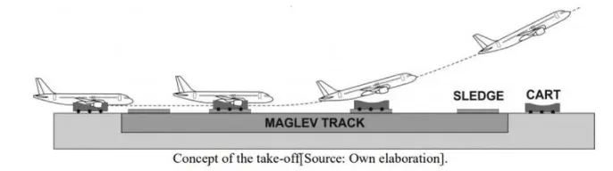
- Types of TAKE-OFF's
There are Two Types of Take-offs,- Vertical Take-Off: The aircraft traveling vertically, this is known as liftoff.
- Horizontal Take-Off: The aircraft that take off horizontally, usually inwolves starting with a transition from moving along the ground on a runway. For example; balloons, helicopters, and some specialized fixed-wing aircraft (VTOL aircraft such as the Harrier). no runway is needed.
- Performance of Take-off: The takeoff distance consists of two parts, the ground run, and the distance from where the vehicle leaves the ground until it reaches 50 ft (or 15 m). The sum of these two distances is considered the takeoff distance. The takeoff distance is generally calculated for maximum weight in a standard atmosphere, usually the worst-case scenario is also calculated which is maximum weight, high altitude, and a standard "hot" day.
- Tyre Design
-
Aircraft tyres and tubes:Aircraft tires may be tube-type or tubeless. They support the weight of the aircraft while it is on the ground and provide the necessary traction for braking and stopping. The tires also help absorb the shock of landing and cushion the roughness of take-off, rollout, and taxi operations. Aircraft tires must be carefully maintained to perform as required. They accept a variety of static and dynamic stresses and must do so dependably in a wide range of operating conditions.
-
Tyre Classification: Aircraft tires are classified in various ways including by Type, ply rating, tube-type or tubeless, and bias-ply tires or radials. Identifying a tire by its dimensions is also used. Each of these classifications is discussed as follows.
-
Types: The common classification of aircraft tires is by type as classified by the United States Tire and Rim Association. While there are nine types of tires, only Types I, III, VII, and VIII, also known as Three-Part Nomenclature tires, are still in production.
-
Type I tires are manufactured, but their design is no longer active. They are used on fixed gear aircraft and are designated only by their nominal overall diameter in inches. These are smooth profile tires that are obsolete for use in the modern aviation fleet. They may be found on older aircraft.
-
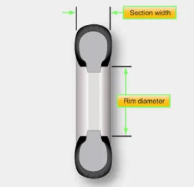
Type III tires are common general aviation tires. They are typically used on light aircraft with landing speeds of 160 miles per hour (mph) or less. Type III tires are relatively low-pressure tires that have small rim diameters when compared to the overall width of the tire. They are designed to cushion and provide flotation from a relatively large footprint. Type III tires are designated with a two-number system. The first number is the nominal section width of the tire, and the second number is the diameter of the rim the tire is designed to mount upon.
-
Ply Rating:
-
Tire plies are reinforcing layers of fabric encased in rubber that are laid into the tire to provide strength. In early tires, the
number of plies used was directly related to the load the tire could carry. Nowadays, refinements to tire construction
techniques and the use of modern materials to build up aircraft tires make the exact number of plies somewhat
irrelevant.when determining the strength of a tire. However, a ply rating is used to convey the relative strength of an aircraft tire. A tire with a high ply rating is a tire with high strength able to carry heavy loads regardless of the actual number of pliesused in its construction.
-
- Tube or Tubeless:
- As stated, aircraft tires can be tube-type or tubeless. This is often used as a means of tire classification. Tires that are made to be used without a tube inserted inside have an inner liner specifically designed to hold air. Tube-type tires do not contain this inner liner since the tube holds the air from leaking out of the tire. Tires that are meant to be used without a tube have the word tubeless on the sidewall. If this designation is absent, the tire requires a tube. Consult the aircraft manufacturer's maintenance information for any allowable tire damage and the use of a tube in a tubeless tire.
- As stated, aircraft tires can be tube-type or tubeless. This is often used as a means of tire classification. Tires that are made to be used without a tube inserted inside have an inner liner specifically designed to hold air. Tube-type tires do not contain this inner liner since the tube holds the air from leaking out of the tire. Tires that are meant to be used without a tube have the word tubeless on the sidewall. If this designation is absent, the tire requires a tube. Consult the aircraft manufacturer's maintenance information for any allowable tire damage and the use of a tube in a tubeless tire.
- Bias ply or Radial
- The classifying of an aircraft tire is by the direction of the plies used in the construction of the tire, either bias or radial. Traditional aircraft tires are bias-ply tires. The plies are wrapped to form the tire and give it strength. The angle of the plies about direction of rotation of the tire varies between 30° and 60°. In this manner, the plies have the bias of the fabric from which they are constructed facing the direction of rotation and across the tire. Hence, they are called bias tires. The result is flexibility as the sidewall can flex with the fabric plies laid on the bias.
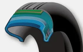
- The classifying of an aircraft tire is by the direction of the plies used in the construction of the tire, either bias or radial. Traditional aircraft tires are bias-ply tires. The plies are wrapped to form the tire and give it strength. The angle of the plies about direction of rotation of the tire varies between 30° and 60°. In this manner, the plies have the bias of the fabric from which they are constructed facing the direction of rotation and across the tire. Hence, they are called bias tires. The result is flexibility as the sidewall can flex with the fabric plies laid on the bias.
-
- Tyre Construction:
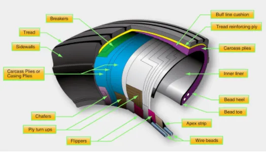
An aircraft tire is constructed for the purpose it serves. Unlike an automobile or truck tire, it does not have to carry a load for a long period of continuous operation. However, an aircraft tire must absorb the high impact loads of landing and be able to operate at high speeds even if only for a short time. The deflection built into an aircraft tire is more than twice that of an automobile tire. This enables it to handle the forces during landings without being damaged. Only tires designed for an aircraft as specified by the manufacturer should be used.
It is useful to the understanding of tire construction to identify the various components of a tire and the functions that contributed to the overall characteristics of a tire. Refer to Figure 6 for tire nomenclature used in this discussion.
- Rolling Resistance:
Rolling resistance sometimes called rolling friction or rolling drag is the force resisting the motion when a body (such as a ball, tire, or wheel) rolls on a surface. It is mainly caused by non-elastic effects that are, not all the energy needed for deformation (or movement) of the wheel, roadbed, etc., is recovered when the pressure is removed.
Two forms of this are:
1. Hysteresis losses
A characteristic of a deformable material such that the energy of deformation is greater than the energy of recovery. The
rubber compound in a tire exhibits hysteresis. As the tire rotates under the weight of the vehicle, it experiences repeated cycles
of deformation and recovery, and it dissipates the hysteresis energy loss as heat. Hysteresis is the main cause of energy loss
associated with rolling resistance and is attributed to the viscoelastic characteristics of the rubber.2. Permanent (plastic)
Deformation of the object or the surface (e.g. soil).
-
Tyre Pressure:
To perform as designed, an aircraft tire must be properly inflated. The aircraft manufacturer's maintenance data must be used to ascertain the correct inflation pressure for a tire on a particular aircraft. Do not inflate to a pressure displayed on the sidewall of the tire or by how the tire looks.
Tire pressure is checked while under load and is measured with the weight of the aircraft on the wheels Loaded versus unloaded pressure readings can vary as much as 4 percent. Tire pressure measured with the aircraft an jacks or when the tire is not installed is lower due to the larger volume of the inflation gas space inside of the tire. On a tire designed to be inflated to 160 psi, this can result in a 6.4 psi error.
A calibrated pressure gauge should always be used to measure inflation pressure. Digital and dial-type pressure gauges are more
consistently accurate and preferred.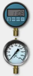
Aircraft tires disperse the energy from landing, rollout, taxi, and takeoff in the form of heat. As the tire flexes, heat builds and is transferred to the atmosphere, as well as to the wheel rim through the tire bead. The heat from braking also heats the tire externally. A limited amount of heat can be handled by any tire beyond which structural damage occurs.
In addition to overheating, underinflated aircraft tires wear unevenly, which leads to premature tire replacement. They may also creep or slip on the wheel rim when under stress or when the brakes are applied. Severely underinflated tires can pinch the sidewall between the rim and the runway causing sidewall and rim damage. Damage to the bead and lower sidewall area is also likely. This type of abuse like any over flexing damages the integrity of the tire and it must be replaced. In dual-wheel setups, a severely underinflated tire affects both tines and both should be replaced.
Overinflation of aircraft tires is another undesirable condition. While carcass damage due to overheating does not result, adherence to the landing surface is reduced. Over a long period of time, overinflation leads to premature tread wear. Therefore, ovennflation reduces the number of cycles in service before the tire must be replaced. It makes the tire more susceptible to bruises, cutting, shock damage, and blowout.
- Brake Forces
- Aircraft Brakes:
Very early aircraft have no brake system to slow and stop the aircraft while it is on the ground. Instead, they rely on slow speeds.
soft airfield surfaces, and the friction developed by the tail skid to reduce speed during ground operation. All modern aircraft are equipped with brakes. Their proper functioning is relied upon for the safe operation of the aircraft on the ground. The brakes slow the aircraft and stop it in a reasonable amount of time. They hold the aircraft stationary during engine run up and, in many cases, steer the aircraft during taxi.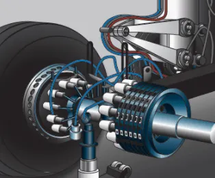
-
Working of Aircraft Brakes:in the typical brake system, mechanical or hydraulic linkages to the rudder pedals allow the pilot to control the brakes. Pushing on the top of the right rudder pedal activates the brake on the right main wheel(s) and pushing on the top of the left rudder pedal operates the brake on the left main wheel(s).
-
Operation of Aircraft Brakes:The basic operation of brakes involves converting the kinetic energy of motion into heat energy through the creation offriction. A great amount of heat is developed and forces on the brake system components are demanding. Proper adjustment, inspection, and maintenance of the brakes are essential for effective operation.
- Aircraft Brakes:
-
-
PART-B:
6)A. With necessary assumptions, calculate the force and power required to push / pull an aircraft by a towing vehicle.
B. Develop the model for the calculated force and power using Simulink.
SOLUTION:
CALCULATION:
Let assume an Aircraft of Airbus A380-800 plane:
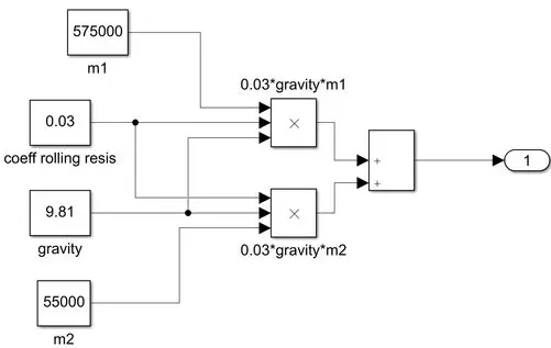
- Mass of the Aircraft `m_1`=575000 Kg
- Mass of the Towing Vehicle `m_2` = 55000 Kg
- Coefficient of Rolling Ground friction for Dry Concrete or Asphalt road `mu_(rr)`=0.03
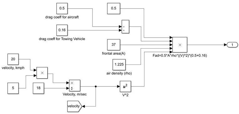
- Frontal Area of the Vehicle A=37`m^2`
- Drag Coefficient of an aircraft `C_(dA)` (aircraft) 0.5.
- Drag Coefficient of a Trowing Vehicle `C_(dT)` (Towing) 0.16.
- Density of Air=1.225 kgm³
- Universel Gravity value g=9.81`ms^2`
- Speed of an Aircraft V=20 kmph =5.556 `ms^2`
- Rolling Resistance Force:
- For the Aircraft:
- Fr(aircraft) = `mu_(rr)*m*g`=1,69,225.5 N
- For the towing vehicle:
- Towing vehicle Frr (Vehic) = `U_(rr)*m_2*g=16,186 N`
- we need to added the mass of the aircraft & an Towing Vehicle for pushing and pulling the aircraft so TOTAL ROLLING
- For the Aircraft:
- Resistance Force Fr(AKT)
- Frr(A&T)=F(aircraft) + Frr(vehic)
- Frr(A&T)=185,409. N
- Aerodynamic Drag Force:
- Fad= `(1/2)*rho*A*V^2*(C_(dA)+C_dT)`
- Fad=461.71N
- Here HILL CLIMBING FORCE is neglected due to the surface of the runway area is a flat surface and gradient percentage is ZERO.
- Total Traction Force:
- F= fRR(A&T)+Fad
- F=1,85,870.71 N
- Total Power:
- P=F.V = 1032.69kw
Excel Calculation:
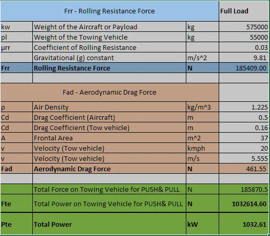
SIMULINK MODEL:
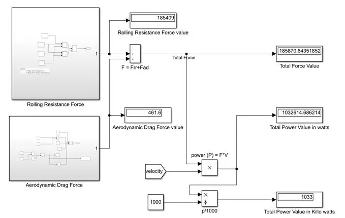
Rolling Resistance Calculation - Subsystem:
Aerodynamic Drag Caculation - Subsystem:
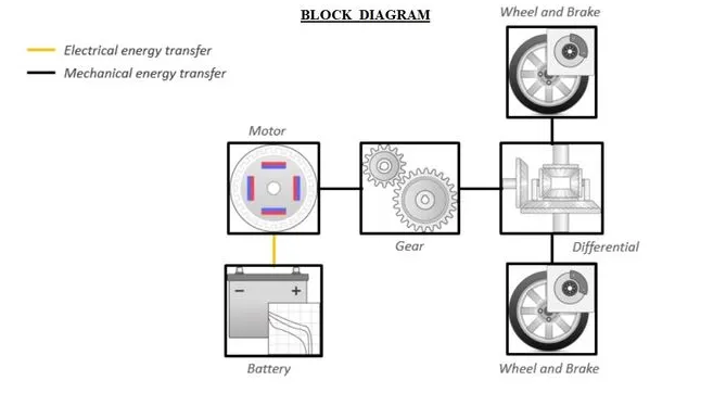
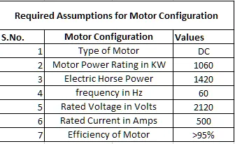
7) A. Design an electric powertrain with type of motor, it’s power rating, and energy requirement to fulfill aircraft towing application in Simulink. Estimate the duty cycle range to control the aircraft speed from zero to highest. Make all required assumptions. Prepare a table of assumed parameters. Draw a block diagram of powertrain. (Hint :DC7 Block)
B. Also, Design the parameters in excel sheet.
SOLUTION:
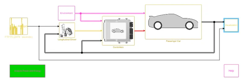
WORKING:
- The above Simulation model explains the work of a Towing Vehicle Which consisted of Longitudinal driver Block, Controllers,
Duty cycle, Vehicle structure and Performance. - Longitudinal Diver Block Acts As The control of Acceclaration and Breaking System That is controlled by Driver
- Duty cycle is the Time duration of the vehicle accelerated and stop in the present time.
- Controller Block deals to control all the components of the vehicle system.
BLOCK DIAGRAM:
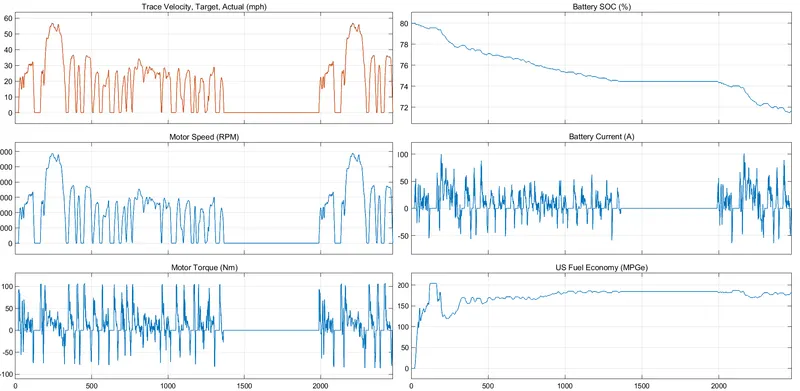
SIMULATION RESULTS:
REQUIRED ASSUMPTIONS IN EXCEL SHEET:
Calculating The Efficiency Of Motor by input energy and output energy:
Lets calculate the values of output energy for 120 min
- Output Energy Eout Pout t
- Where, Pout = Output Power, t= Time Period =120 min
- So Here Pout 1033, kw& t=120min=120*(1/3600),hr
- Eput= Pout t= 1033
- Eout 34.433, kwh
- Lets calculate the values of input energy for 120 min
- Input power Pils Taken From Above Moter Power Rating Configuration As 1060,kw
- The Input Power is calculated from rated voltage and rated current
- `P_(In)=V_r*I_r`
- `P_(In)=1060 kw`
- Input Energy `E_(In)=P(In)*t`
- Where, `P_(In)= Input Power, t= Time Period=120 min`
- `E_(In)=35.33 kwh`
- Input power Pils Taken From Above Moter Power Rating Configuration As 1060,kw
- The Efficiency Of Motor by input energy and output energy calculated as: From eq (3) & (4) = 97.4%
• ESTIMATE THE DUTY CYCLE RANGE TO CONTROL THE AIRCRAFT SPEED FROM ZERO TO HIGHEST.
The Duty cycle is calculated by Output power and Input Power Values, Now the Values are Mentioned Above:
Output Power Pout = 1033, kw and Input Power Pin 1060, kw
The Duty cycle is denoted by D = `P_(out)/P_(In)*100`= 97.4 %
The DUTY CYCLE (D)=97.4%
So THE DUTY CYCLE RANGE TO CONTROL THE AIRCRAFT SPEED FROM O to 97.4%