Week-7 Challenge: DC Motor Control
-
- Explain a MATLAB demo model named ‘Speed control of a DC motor using BJT H-bridge’.
- Comment on the armature current shoot-up from the scope results.
- Refer to the help section of ‘The Four-Quadrant Chopper DC Drive (DC7) block’. Compare it with the H-bridge model.
Solution:
A) Model:
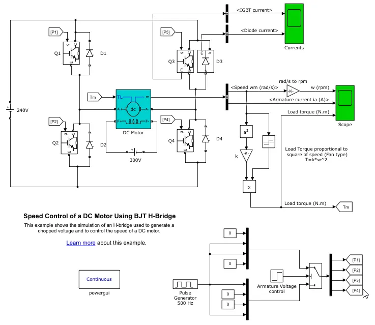
This example shows the simulation of an H-bridge used to generate a chopped voltage and to control the speed of a DC motor.
It consists of,
- IGBT acting as BJT in power switching devices
- We have a standard DC Motor with (5 HP 24V 1750 rpm). It simulates a fan type load (where Load torque is proportional to square of speed). The armature mean voltage can be varied from 0 to 240 V
- We have Pulse Genarators which is used to controll the 4 BJTs.
- We have 4 diodes which will act as free- wheeling diodes at ceratin stages of operation.
- A field current source of 300V.
Operation:
- Here four switches are used Q1,Q2,Q3,Q4. Pulses P1, P2, P3, P4 are conected with corresponding switches from the Pulse Genrator block below.
- During first half of the operation, Q1 and Q4 are closed by giving 1V to IGBT'S. Then here, current from battery passes through Q1 and Q4. At this time, Diode D2,D3 are used as free wheeling diode in this state. In this case Forward motoring and forward breaking are held.
- In Second half of the operation cycle, Q2 and Q3 are closed by giving 1V to IGBT's, current from battery passes through Q2 and Q3. Diode D1,D4 are used as free wheeling diode in this stateln this case reverse motoring and reverse breaking are held. The current direction change its direction in this state.
- Both the states are occuring in 0.5 seconds in their sample time. Thus DC supply converted and feeded to the armature of the motor.
- Here free wheeling diodes are used as a safety purpose of this inverter circuit as when the flow of current on low values protects the circuit and machine by feed backing the current or in high voltage fluctuvations voltage get splited as protection to the motor and circuit components.
- In motor operation, armature terminals are connected with a 240V along the inverter circuit and field windings are connected with 300 V DC suppy to act as a electro magnet for the motor.
- The load torque is given as mechanical input to the motor for its reference.
- Thus through this magnetic fields generated, variable current carring conductors in rotor armature produces forces according to fleming left hand rule principle. Thus the motor starts to rotate.
Result:
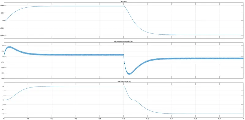
Speed of motor:
• Initially increases to O to nearly 900 rpm upto 0.5 secs (Forward motoring action takes place).
• Then speed reduces to 0 rpm (Forward dynamic breaking action takes place).
• Then speed increases from 0 to -900 rpm at upto 1 sec( Reverse motoring action takes place).
• Then reverse dynasmic breaking occurs.
Load torque of motor:
• Initially torque increase from 0 to 0.5 secs in forward motoring action.
• Then torque reduces to 0 Nm in forward dynamic breaking mode.
• Then torque increases in reverse direction in reverse motoring action upto 1 sec.
• Again torque reduce to zero.
B) The armature current shoot-up is due to the sudden increase in voltage during the starting period. We have set of duty cycle to 75%. This means 75% of the 240V input (180V) will be across the armature windings.
This can be easily changed by regulating the duty cycle.
Below are the results for 50% and 35%,
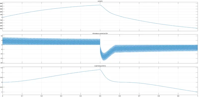
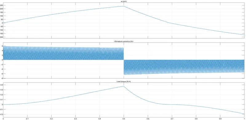
Conclusion: To reduce the shootup, we need to control the duty cycle gradually fro 0-100%. This will in-effect gradually build the current flowing accross the armature.
C)
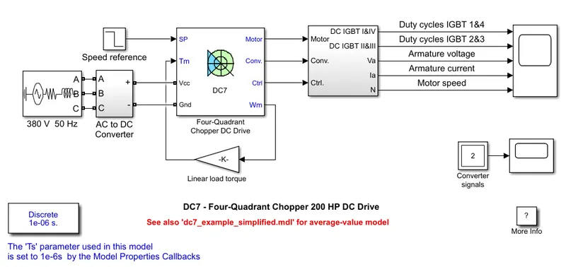
DC7 Connections:
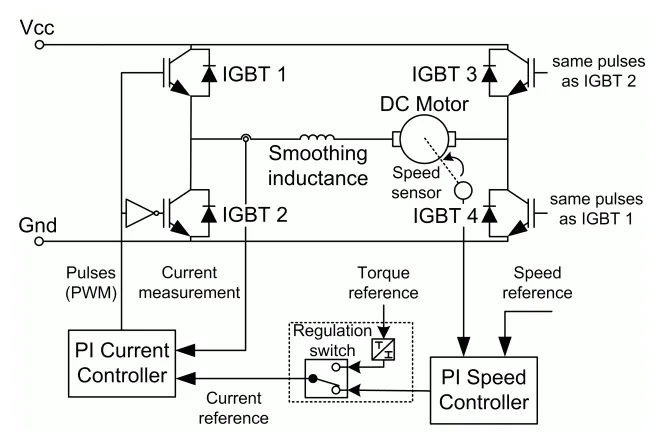
The Four-Quadrant Chopper DC Drive (DC7) block represents a four-quadrant, DC-supplied, chopper (or DC-DC PWM converter) drive for DC motors. This drive features closed-loop speed control with four-quadrant operation. The speed control loop outputs the reference armature current of the machine. Using a PI current controller, the chopper duty cycle corresponding to the commanded armature current is derived. This duty cycle is then compared with a sawtooth carrier signal to obtain the required PWM signals for the chopper.
The main advantage of this drive, compared with other DC drives, is that it can operate in all four quadrants (forward motoring, reverse regeneration, reverse motoring, and forward regeneration). In addition, due to the use of high switching frequency DC-DC converters, a lower armature current ripple (compared with thyristor-based DC drives) is obtained. However, four switching devices are required, which increases the complexity of the drive system.
Working:
• Here Four Igbt switches are used. Here pulses are given from Pl current controller, that controles the pulses by comparing armature current measurement and current referance.
• Current referance can be generated by using regulation switch in that torque referance and PI speed controller pulses,that internally compared by speed of motor and refrance speed Mainly speed controlled by current controller.
• In this case Four quadrant operations are performed.
• Forward motoring mode,forward regenerative breaking mode: Q1,Q4 are on and Q2,Q3 are in off.
• Reverse motoring mode,reverse regenerative breaking mode: Q2,Q3 are on and Q1,Q4 are in off.
Comparisons:
• In DC7 chopper model speed controlled by varying current pulses from Pl current controller and in H-brige model speed controlled by varying duty cycles voltages.
• Here regenerative breaking in occring while in H-bridge model breaking is occured by changing polarity of current flow.dynamic breaking occurs in it.
• In four quadrant DC chopper model smoothing inductance is used for smooth increase and decrease in current flow which inturns controlling the motor speed smoothly.while inH-bridge it is not present. Here the operation is discreat and in H-bridge model it is continuous.
• Hence 4 quadrant DC choppers are used mostly in electric vehicles.
2. Develop a 2-quadrant chopper using simulink & explain the working of the same with the relevant results.
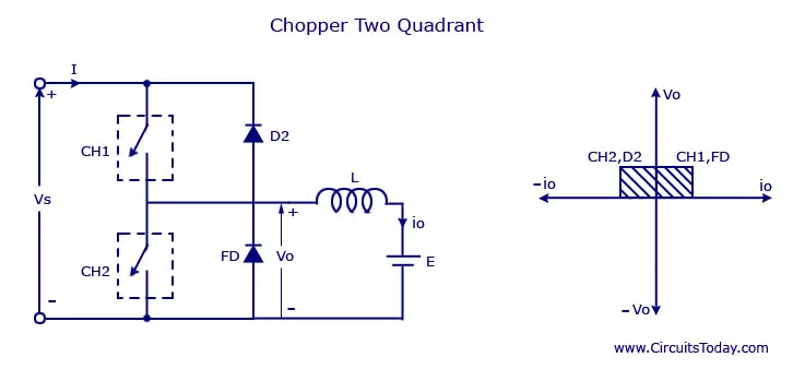
DIAGRAM:
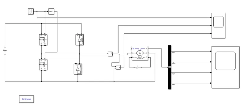
SIMULINK DIAGRAM:
OPERATION:
FIRST QUADRANT OPERATION :
For first quadrant operation, IGBT 1 is kept ON, IGBT 2 is kept OFF and is operated. The load gets directly connected to the source and hence the output voltage becomes equal to the source voltage.
When IGBT 1 is switched OFF, the load current freewheels through D1. During this period, the load voltage and current remain positive. Thus,
both the output voltage and load current are positive and hence, the operation of the chopper is in the first quadrant.
SECOND QUADRANT OPERATION :
To obtain second quadrant operation, IGBT 2 is operated while keeping the IGBT 1 off. When IGBT 2 is ON, the DC source in the Inductor L stores energy during the on period of IGBT2.
When IGBT 2 is turned OFF, the current is fed back to the source through D2. It should be noted at this point that (E+Ldi/dt) is more than the
source voltage . As load voltage is positive and is negative, it is the second quadrant operation of the chopper. Since the current is fed back
to the source, this simply means that load is transferring power to the source.
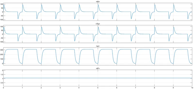
OUTPUT:
3.Explain in a brief about operation of BLDC motor.
BLDC motor named as brushless dc motor having high effenciency than other types of motors. This motor is also known to be synchronous motor
Construction:
Most of the motors are having brushes in their rotor as it transfers current into the rotor circuit. But here differently rotor is placed with permanent magnet. The stator coil is wounded with coils, they are stationary but producing variable DC voltages for rotating the permanent magnet as changing the magnetic field of stator poles continuously.The controlling of motor is by changing the magnitude and direction of current flowing through the stator windings.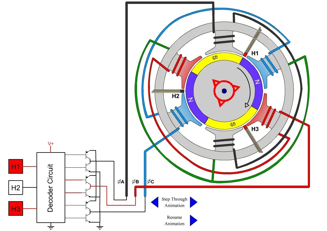
A BLDC motor with three colls on the stator will have six electrical wires (two to each coil) extending from these coils in most implementations three of these wires will be connected internally, with the three remaining wires extending from the motor body. Wining in the BLDC motor case is more complicated than simply connecting the power cell's positive and negative terminals we will look more closely at how these motors work in the second session of this series.
OPERATION: There are 3 windings as you can see in the above image. Each of these phases are electrically 120 degrees apart from each other. The winding around the stator are wound such that current enters from the source and leaves back to complete the circuit.
The decoder circuit works such that the three phases are active 120 degrees apart, as you can see in the below diagram,
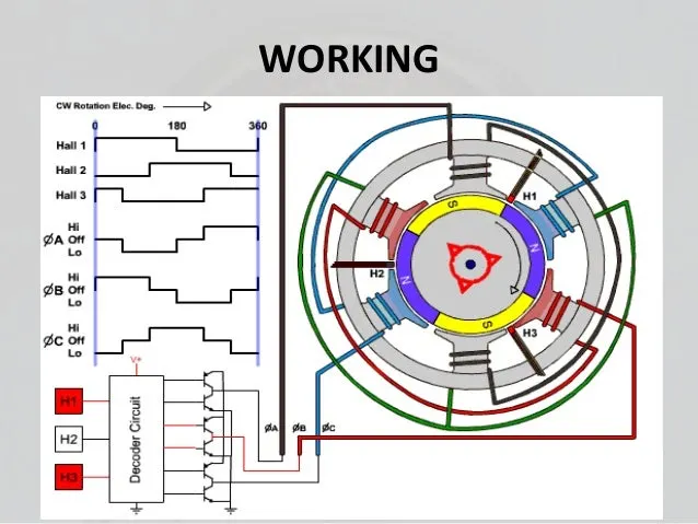
The semi-conductor switch has a duty cycle which creates a rough sinusoidal wave as output, which is then fed to the motor - stator windings and is spread in time in such a way that we create a RMF - Rotating Magnetic Field.
Now, the rotor tries to follow this moving stator current and thus creating a motion.
END.