Week-6 Calculate the Stretch Ratio by comparing the ELFORM (-2,-1,1,2) with Ogden_Material Model.
STRETCH RATIO BY COMPARING VARIOUS ELFORM (-2,-1,1,2)
AIM:
To simulate tensile behavior for the solid cube model by using appropriate boundary conditions and finally compare the results from the simulation to the plot stretch ratio 5.
PROCEDURE:
- Initially a Cube model is created with solid elements with a size of 10mmx10mmx10mm with the help of Hypermesh.
- It is then exported to Lsprepost.
- Material is defined with Ogden_Material
- Section is defined with Solid and ELFORM as -1,-2,1,2 for different simulations.
- Material and section is assigned to the Part.
- Boundary prescribed motion is set by defining the curve for the displacement so that tensile stretch will happen to the part. Since the simulation requried 50%+ strain, 55mm displacement is defined.
- Boundary SPC is defined in such as way that it behaves like a real-time boundary condition.
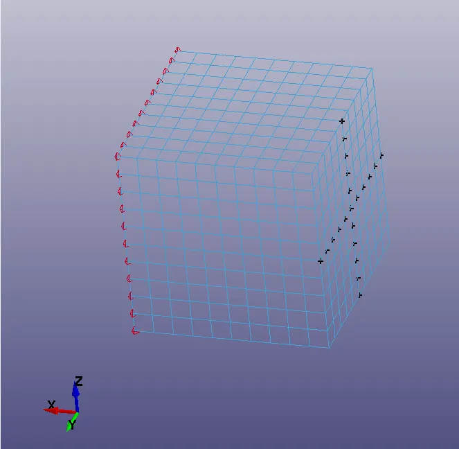
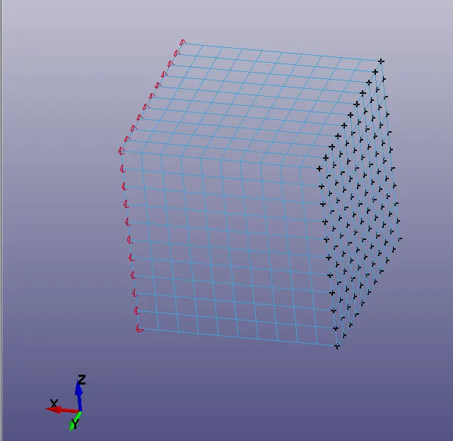
Here the costraints are defined in such a way that Z direction is arrested in the horizontal direction of the middle row and Y direction is arrested in the vetical diecrion of the midlle row so that compression is free to happen. Also the entire constrain face is arrested in X direction. so that one middle node will be constrained in all direction which will make the model stable while tensile force act on the part.
- Control termination is defiend with 1 as termination time and 0.1 as DT in Database D3plot.
- Database Extent Binary is aslo defined to get the strain output.
Here for this simulation, IMPLICIT METHOD is followed. The reasons are given below.
1. The simulation carrying out is a static simulation.
2. Explicit menthod is mainly used for robust simulations like car crash having high velocity impact but here the simulation is not robust.
3. This is a dynamic problem (but static in manner). here the problem is changing wrt to time.
- Control Implicit General is defined with DT0 as 0.1 and IMFLAG as 1 so that analysis will gets switched to implicit method.
- Control Implicit Solution is defined with NSOLVER as 12.
- Control Implicit Solver is defined with LSOLVER as 4 which includes a SMP parallel multi-frontal sparse solver.
- The model is defined with all the necesaary parameters and checked in model checking and is saved.
- The model is ran in Manager and the the results are saved.
RESULTS & GRAPHS:
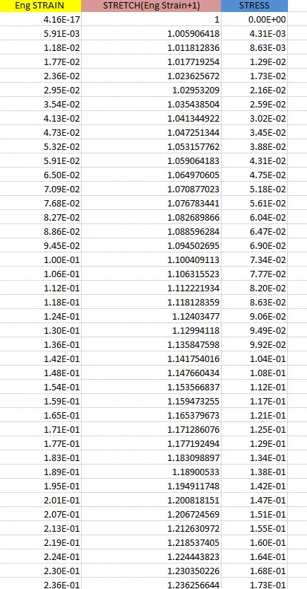
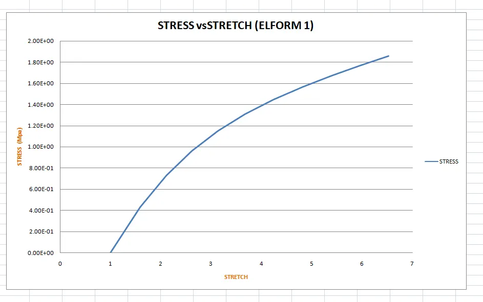
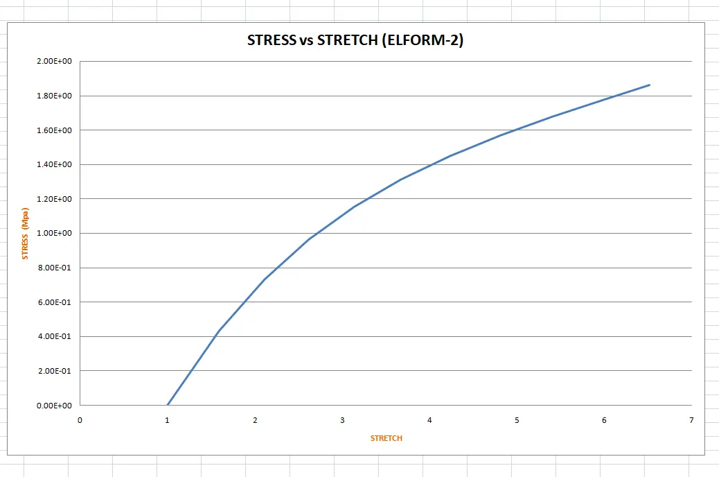
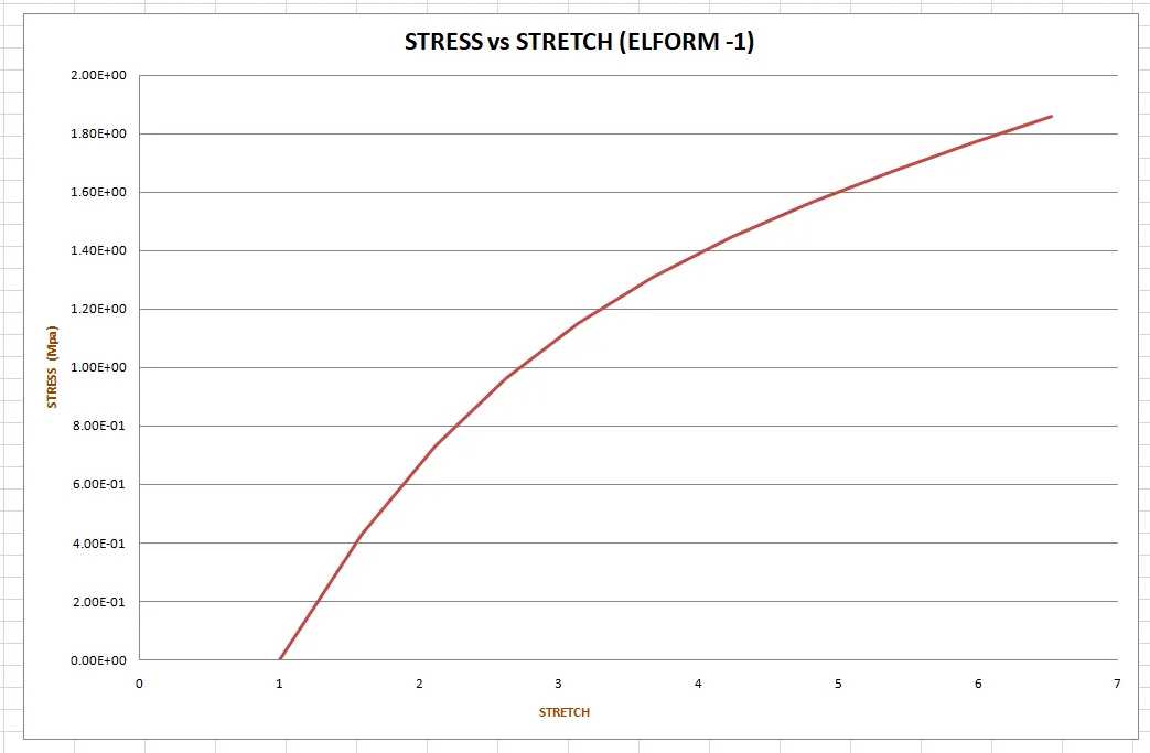
- The output of stress and strains from Post FringeComp Stress/Strain is given as true stress and strains. since the output needed as stress vs stretch plot, stretch ratio needed to be calculated.
- Stretch ratio l is defined as the ratio between the final length L and the initial length L0 of a component i.e. it is equal to (1 + engineering strain)
- An element is choosen for calculating the result and stress strain curve is plotted.
- The data is taken to an excel sheet for various elforms. The below table is an example of elform-1
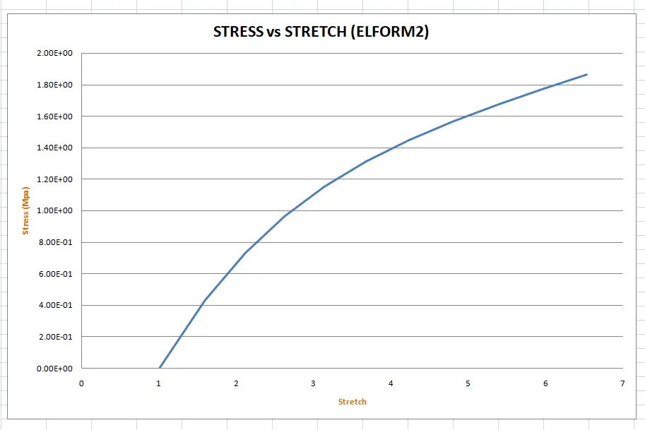
The plots of varios elforms are given below:
ELFORM 2:
ELFORM 1
ELFORM -2
ELFORM -1
CONCLUSION:
The simulation is ran for vaious elforms and the results are plotted in an excel sheet. Stretch ratio is found by adding 1 to engg strain and the graph is plotted for stress and stretch.
From the comparison of all the plots of ELFORMs with the Uniaxial plot given in the question. It is found that almost every ELFORM is behaving in an simlilar manner but ELFORM -1 and ELFORM -2 are showing more resemblance with the graph and hence it is proved that ELFORM -1 and -2 are the suggested ELFORM for solid elements for implicit analysis.
Note: All the necessary files are attched with this report :)
Thanks,
Rakesh