Week 5 - Turbulence modelling challenge
Turbulence :
- Introduction:
- Turbulence is an irregular motion which in general makes its appearwnce in fluids, gases or liquids, when they flow past solid surfaces or even when neighbouring streams of same flow past or over one another.
- Turbulent fluid motion is an irregular condition of flow in which various quantities show a random variation with time and space co ordinates , so that statistical distinct average values can be discerned.
- Turbulence is characterized by random fluctuations that almost mandates the use of statistical method for analysis. Unfortunately, statistical methods prevent us from performing certain operations.
- Turbulence is a contimuos phenomenon . The navier stokes equations govern all the physics within the turbulent flow.
- Even the smallest scales occuring in a turbulent flow are ordinally for lomger than any molecular length scale.
- Vortex stretching: Vortex lines in a turbulent flow are non parallel and there are strong vorticity within the turbulent flows. the majority of vorticity within the turbulent flow resides inside the smallest eddies.
- Turbulence consists of spectrum of scakes ranging from the largest to smallest . The eddies withion this spectyrum overlap and form the cascade process. turbulent flows are always dissipative and most dissipation occurs at the smallest scales.
- Large eddies migrate through the flow and carry smaller eddies with them. Most of the energy within the flow is at large eddies and are most persistent.
- Enhanced diffusivity: Diffusion is greatkly enhanced with turbulence.
- Turbulence is dominated by large energy bearing eddies. They are responsible for enhanced diffusivity and carry the most energy. Small eddies dissipate most energy through viscous action and turbulent dissipation is proportional to that recieved from large eddies.
2. Kolmogrov scale of turbulence:
Smallest scales of turbulence can be estimated through advanced theoretical fluid dynamics. Cascade process of turbulence represnets transfer of turbulent kinetic energy from larger eddies to smaller eddies.
Universal equilibrium theory states that smaller eddies should recieve energy from larger eddies and dissipate that energy at nearly an equal rate into heat and accoustic radiation. The motion of small scales depends mainly on which larger eddies supply energy and kinematic viscosity is equal to `-(dK)/(dT)`
`eta=((nu^3)/(epsilon))^(1/4)`
`tau=((nu/(epsilon))^(1/2))`
`nu=(nu*epsilon)^(1/4)`
The first equation represnts the smallest length scale. The second equation represnts the time scale and the third equation represents theb velocity scale.
Most simple example is fourier decomposition of energy into wave numbers .
The turbulent kinetic energy is the amount of energy within the K and K+dK
`k=integrationE(k)dK`
`E(k)`depends on `nu and epsilon`.
The nergy flow is contained within large eddies,`l`
`epsilon = (k^(3/2)/l)`
`l>>eta`
`l/eta=(l/(nu^3/epsilon)^(1/4))=Re^T=k^(1/2)*l/(nu)`
`Re^t`is the turbulent reynolds number.
- The range of scales is dependent upon turbulent reynolds number
- An energy cascade transfers energy from large scale eddises to small scale eddies
- An intermediate range exists, where there is equilibrium within the cascade that is called inertial range
`E(k)=c*epsilon^(2/3)*k^(-5/3)`
`(1/l)<
3.Boundary layer and law of wall:
- It is an emperical theory
- The streamwise velocity component near the wall varies logarthimcally with the distance from the surface .
- the energy cascade of Kolmogorov also exists in the boundary layer flows.
`u_tau=(tau_w/rho)^(0.5)`
- Friction velocity: Velocity scale close to the solid boundary
- The mean velocity gradient can be corelated as : `(delu)/(dely)=(u_tau/y)*F((u_tau*y/nu))`
Where F is a universal funmction.
If F varies with (`(u_tau/y))`it will depend on the kinematic viscosity.
`u/u_tau=(1/K)ln(u_tau*y)/nu+C`
Where C is the constant. The value of C is 5;
- Typical turbulent boundary layer profile is given as
`u+=(u/u_tau)`
y+=(u_tau*y)/nu
- Velocity profile matches with the law of wall for values of y plus greater than 30.
- There are three main regions of boundary layer ; Viscous sublayer,Log layer,Defect layer.
- The log layer separates the viscous sub layer from the defect layer.
4. Turbulence modelling:
In general, flows can be classified as
- Laminar : Low reynolds nu,ber flow
- Transition : Increasing Reynolds number flow
- Turbulent : High reynolds number flow.
Reynolds number : Dimension less number expressed as the ratio of inertial forces to viscous forces.
`Re=(rho*U*L)/mu`
Thje reynolds nu,ber is dependent on the length scale of the flow. that is hydrodynamic entrancxe length.
The transition of laminar flow to turbulent flow occurs at certain reynolds numbner. , for extrenal flows, the Reynolds number along whichg the flow changes to turbulemt is 500000. And along an obstacle, it is 20000.
- turbulent flows contains wide range ofg eddy sizes.
- Turbulent structures are unsteady, 3D , irregular , stochaistic that fluctuates with time and space. ANd it is unpredicatbel in nature.
- Energy is transferred from larger eddies to smaller eddies . In the smalles eddies , turbulent energy is converted to internal energy by viscous dissipation.
Mean and instantaneous velocities:
- The instantaneous velocity is the summation of time averaged velocity and the fluctuation component of the velocity.
- The time averaged and the fliuctuationg component of the velocity must be equal to zero.
- The RMS of the fluctuating is not nessecarily zero.
- the turbulent kinetic energy is the sum if three normal fluctuating velocity components
`K=0.5*(baru^2+barv^2+barw^2)`
Approaches to track the turbulence:
- Direct numerical simulation
- Large eddy simulation
- Reynolds averaged navier stokes simulation
Direct numerical simulatuon:
- Numerically solves full unsteady navuier stokes equation.
- Resolves whole s pectrum of scales
- No modelling is required
- Too costly for industrial use.
Large eddy simulation:
- Solves spatially averaged navier stokes equations
- large eddies are directly resolved. eddies smaller than the mesh is modelled
- Less costly than DNS. Still not used due to hif=gh computational requirements
Reynolds averaged navier stokes Simulation:
- The instantaneius navier stokes equations can be written as :
`rho*((delbaru_i)/(delt)+baru_k*(del(baru_i))/(delx_k))=(delbarp)/(del(x_i))+(del/(delx_j)(mu*(delbar(u_i))/(delx_j)))+(delK_ij)/(del(x_j))`
Here `R_ij`is the Reynolds stress tensor. this stress tensor is solved.
- It can be solved in two ways:
reynolds stress models and eddy viscosity models
turbulence models available in fluent are as folows :
- One equation model- Spallart Allamras model
- Two equation kodels: Standard K-epsilon, RNG K -epsilon, Realiozable K -epsilon, Standard K-omega SST models
- Reynolds stress models
- k-kl-omega transition model
- detached eddy simulation and large eddy simulation
Two equation model:
Two transport equations are solved, giving two independent scales for calculating dynamic eddy viscosity.
Virtually all use the transport equations for turbulent kinetic energy:
`rho*(Dk)/(Dt)=del/(del(x_j))([(mu+mu_t/(sigma_k)*(delK/(delx_j))]+P+rho*epsilon`
Here , P is the production rate and rho times epsilon is the dissipation rate
- Standard K-epsilon model:
This is the most widely used model. It is roibust and to some extent accurate. It contains submodels for compressiblity, buoyancy and combustion.
The disadvantages are : It is poor for large pressure gradient. It is inaccurate for spreadfing rate of jets.
- Realizable K-epsilon:
Thius is superior for flows involving rotation and circulation.
- Spallart -Alllamras model:
This is a one equation model. this was developed for cost efficient, aerospace applixations.
Simulation :
- The geometry is loaded inside the design modeller.
- It is then tranferred to the tio the Ansys mesher for mesh generation.
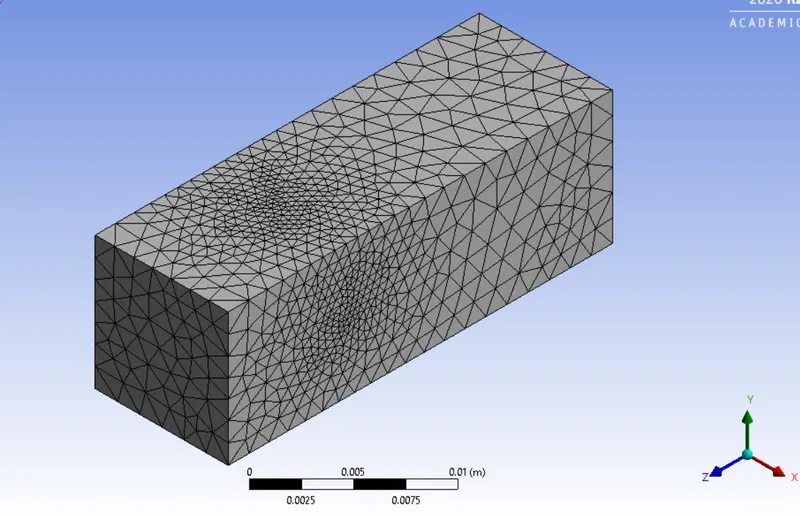
Automatic meshing is performed.
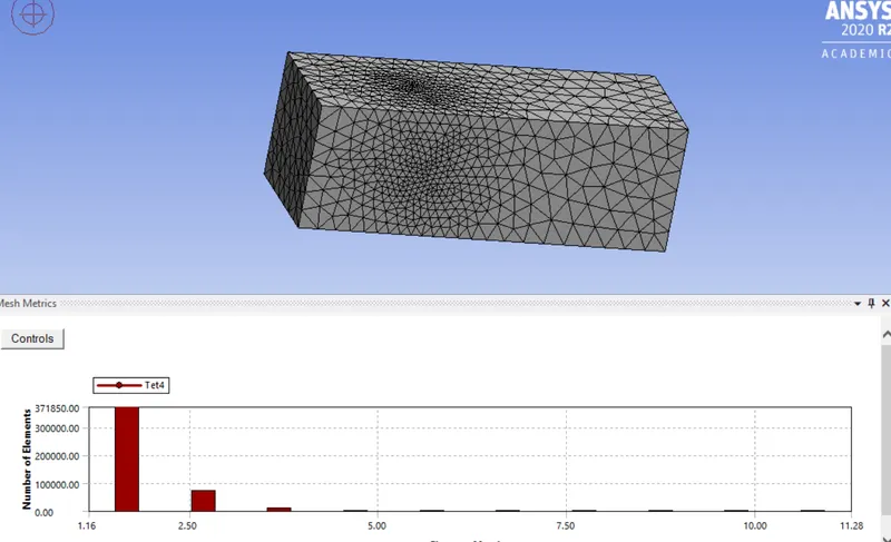
Aspect ratio:
Orthogonal quality:
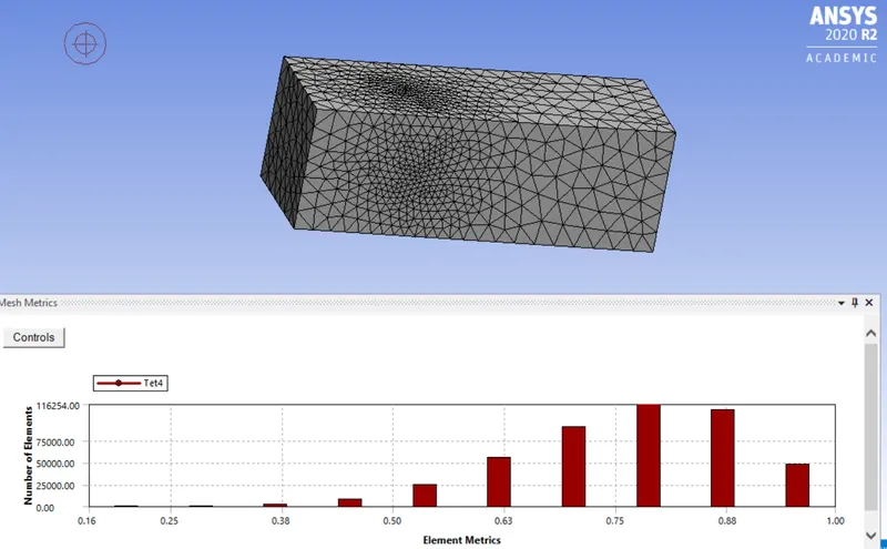
Number of elements : 452491
- creating named selection:
To provide the boundary condituions, named selection is done: the named selections are thge inlet, outlet, the golf balls, the symmetry surafaces.
- The meshed file is then imported to set up :
Solver type : Pressure based . Since the mach number is very less.
Steady state simulation and the velocity formulation is absolute.
Under the physics tab; Operating conditions are kept default.
Turbulence model selected is realizable k -epsilon model. Materuial selected as the fluid medium is air.
- Boundary conditions:
1) Inlet: Velocity inlet, the flow velocity at the inlet is 60 m/s.
The spersonic gaugfe pressure is zero.
2) Outlet : It is the pressure outlet. the gauge pressure at the oiutlet is set to zero.
3) The other boundarieds are specifically wall . Wall boundary conditions are applied at them.
- Convergence criterion is set to 1e-03
- hybrid initialization is applied . And the solution is run for 500 iterations.
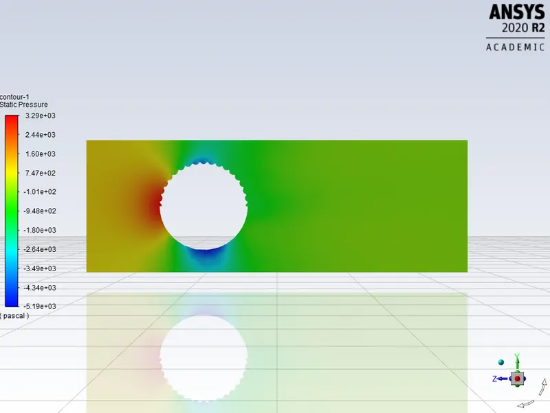
- Contours of pressure and velocity is crewated along a plane .
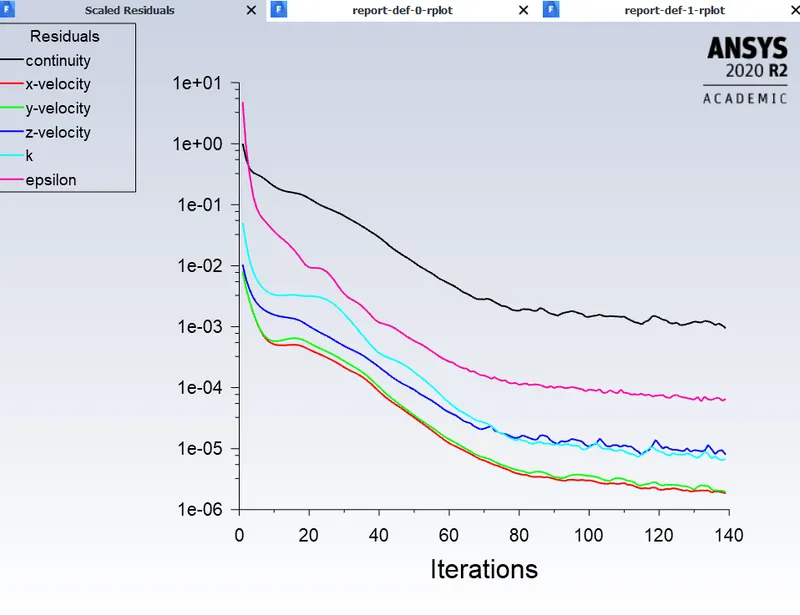
The residuals plot indicates the soliution has converged.
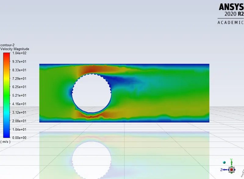
Velocity contour:
Pressure contour:
Post processing:
Along the plane, velocity is plotted alonfg with the vectors:
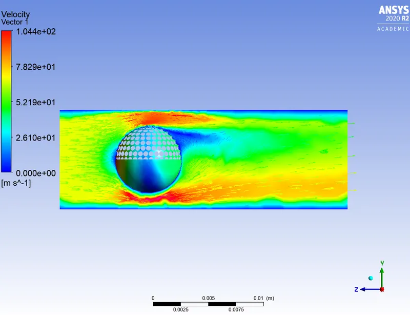
There is a region of flow separation near the ball. this is the region where the velocity comes to zero.
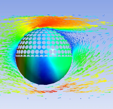
Zooming in the region of circulation or vortices generation:
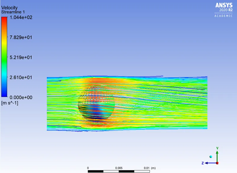
If velocity straemlines are visulaized from the inlet and through out all domains :
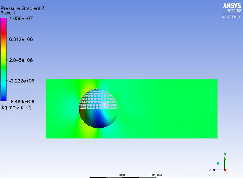
Pressure gradient along the z axis:
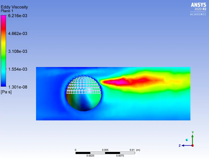
Eddy viscosity:
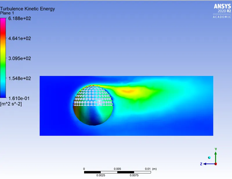
Turbulent kinetic energy:
- Reason for boundary layer separation:
Boundary layer separation attributes to presnce of large adverse pressure gradient in the direction of the flow. Boundary layers tyend to separate from fluid bosies, when there are increasing pressure in the direction of the flow. Increasing fluid pressure incrteases potential energy of the fluid and decreases the kinetic energy of the fluid. so the fluid decelarates.
- In the simulation above, the separation occurs in the front of the ball. the ball decelarates in moving forward. since the flow sepoaration occurs in the direction of the fluid flow, the ball moves fiorward.
- DNS is not used in this case because of the requirement of high compuatational time .
The effect of dimples on the golf balls:
The dimples act as artificial turbulators, creating turbulence next to the ball surface and creating two layers of air going around the ball. The top layer is going faster than the bottom layer, i.e., air clings to the ball’s surface, which creates turbulence. This reduces the drag and helps the ball to travel farther than a smooth one. This is another new term: drag. Drag is a force component which arises as a result of a difference in velocity of a solid and fluid body, and it opposes the solid motion through the air—in this case, the golf ball. A dimpled golf ball probably only has about half the drag of a smooth one.
Similar to drag, there is another component called “lift”. Lift occurs when the fluid is turned by the solid, which creates an opposing force. If the ball spins in a way that pushes the air downward, then an upward lift force is experienced by the ball. One important thing to note is that this factor comes into play only when the ball is spinning. Why? The spinning action makes the air pressure on the bottom of the ball higher than the air pressure on the top, and this imbalance creates an upward force on the ball. Ball spin contributes to half of a golf ball’s lift. The other half of lift is provided by the golf ball dimples, which allows for optimization of the lift force.