Week - 4
1. To implement control logic of washing machine, with given sequence:
- If the power suplly is available system gets activated.
- If the water supply is not available, stope the process and indicate through LED.
- Soaking time should be 200 secs, followed by washing time of 100 secs.
- Then rinsing happens for next 20 secs and dryer runs for 50 secs.
After all the process has completed, turn ON the finished LED.
Answer:
Control Logic : Control logic is considered as the key part of a software program, which controls the program. The commands will be given by the user to which the control logic responds and acts by itself based on the automated tasks structured into the program. Control logic can be modelled using a state diagram, which is a form of hierarchial state machine.
Stateflow: Stateflow is the graphical represerntation of the state transition diagrams, flow charts, state transition tables and truth tables. It is used to describe how MATLAB algorithms and Simulink models react to inputs, events and time-based conditions. It enables to design and develop supervisory controls, task, scheduling, fault management, communication protocols, user interface and hybrid systems. With Stateflow we can model combinatorial and sequential decision logic that can be simulated as a block within Simulink or executed as an object in MATLAB. It will help to analyse and debug the logic while executing.
Washing Machine : Washing machine is a home appliance that is used to wash laundry, where we use water for cleaning and the user adds the detergent in solid, liquid or powder form to wash the clothes in water.
Washing Machine are of mainly 2 types :
1. Semi-Automatic : It is the type, where the machine need manual assistance to get the job done, where we will have to pour the water manually, or set the timer, etc.
2. Fully-Automatic: It is the type, where there is no need of manual assistance. It is more budget- friendly, has great range of functionality and we will get fullyautomated functions. Futher, Fully - automatic wahsing machine can be of 2 types:
- Front Load washing machine : In front load type, we will load the washing machine from the front. The drum washes, rinses and spins the laundry. Here, the drum itself moves and tosses the clothes from one diretion to the other, it mostly uses agitator washing style for washing clothes and rinse.
- Top Load washing machie : In top load type, we will load the washing machine from the top, and the drum doesn't move here, instead the base alone rotates and moves the clothes. The base will move in both clock-wise and anti-clockwise direction to wash the laundry.
Procedure:
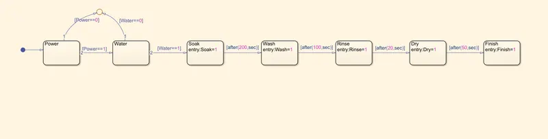
- Create a chart block defining stateflow according to the given conditions
- In the chart block, a junction is provided to terminate signal flow and return to null value, when there is no power or water supply.
- If the power supply is OFF, then the process will be terminated at junction, else 1 is carried out.
- If the water supply is OFF, then the process will be terminated at junctions, else 1 is carried out.
- When power and water is ON, the soak block gets activated and soaking function is done.
- After 200 secs, the soaking is completed and wash block gets activated, washing is carried out.
- After 100 secs, washing is completed and Rinse block gets activated, rinsing is carried out.
- After 20 secs, rinsing is completed and dry block is activated and drying action takes place.
- After 50 secs, drying is completed and Finish block is activated.
- Finish block is to stop the process and to exit the chart.
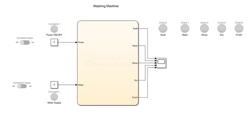
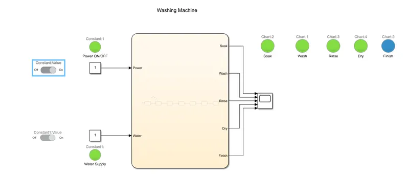
- Chart block is connected to constant inputs defined as power and water supply. Slider switch is provided for power and water supply seperately.
- Inputs are defined as Power and Water, where as the outputs are defined as Soak, Wash, Rinse, Dry and Finish.
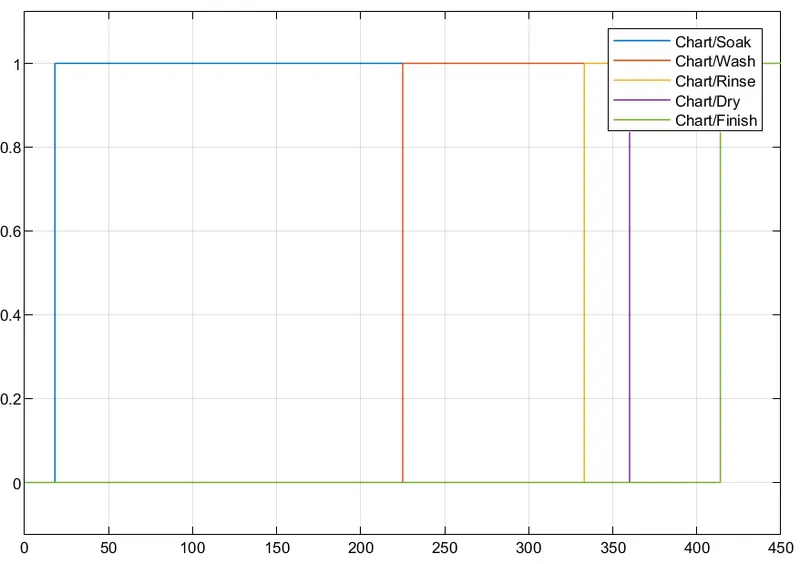
- Outputs are connected to a single scope to plot the output.
Simulink model for the Washing machine with given conditions:
Control logic diagram:
When the power and Water supply is ON at t=10 secs:
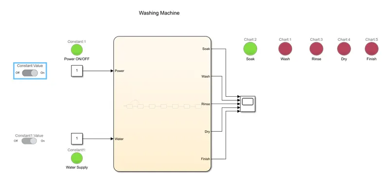
When power and water supply is ON at t=230 secs:
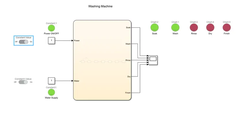
When the power and water supply is ON at t=330 secs:
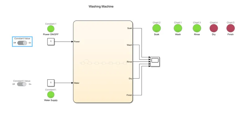
When the power and water supply is ON at t=350 secs:
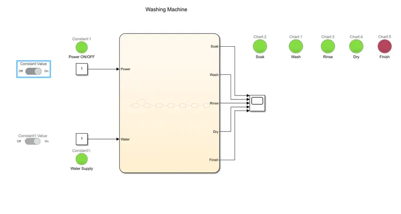
When the power and water supply is ON at t=450 secs:
Output plotted in Scope at t=450 secs:
2. Simulink chart for Gear shift according to given conditions:
| Speed Range (kmph) | Gear |
| 0 to 15 | 1 |
| 16 to 25 | 2 |
| 26 to 40 | 3 |
| 41 to 60 | 4 |
| 61 and above | 5 |
Answer:
The manual transmission or the gearbox is the second elemenet in the power train of automobile. It uses driver operated clutch, usually engaged or disengaged by a foot pedal or hand lever for regulating the torque transfer frm the engine to transmission and the gear selector can be operated by hand. The main function of a gearbox are, (1)to provide the torque needed to move the vehicle under different conditions - for this the gear ratio between the engine crankshaft and vehicle drive wheels will be changed. (2) To shift into reverse so that the vehicle can move backward. (3) To shift into neutral to start the engine.
Working:
In the gearbox, the tertiary counter shaft is mashed into clutch with use of couple of gears so the countershaft is always in the working condition. When the tertiary shaft is brought in contact with the main shaft by making use of meshing gears the main shaft starts to rotate according to the gear ratio. When the driver wants to change the gear he simply press the clutch pedal which disconnects the tertiary shaft with the engine and connects the main shaft with the tertiary shaft by another gear ratio by the use of gearshift lever.
Procedure:
- Create a chart block for the given conditions.
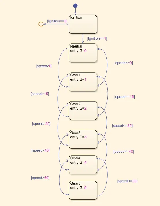
- In the chart block, a junction is provided to terminate signal flow and return to null value.
- If Ignition is OFF, the process is terminated at junction, else 1 is carried out.
- If speed is less than or equal to 0, process is terminated and gear 0 is activated, at the junction else 1 is carried forward.
- If speed is greater than 0 and less than or equal to 15, flow is terminated and gear 1 is activated.
- If speed is greater than 15 and less than or equal to 25, flow is terminated and gear 2 is activated.
- If speed is greater than 25 and less than or equal to 40, flow is terminated and gear 3 is activated.
- If speed is greater than 40 and less than or equal to 60, flow is terminated and gear 4 is activated.
- If speed is greater than 60, flow is terminated and gear 5 is activated.
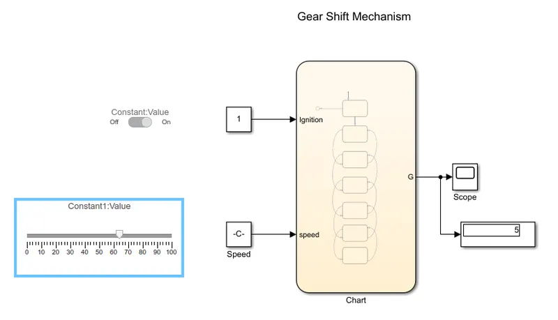
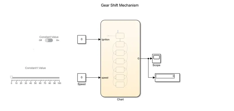
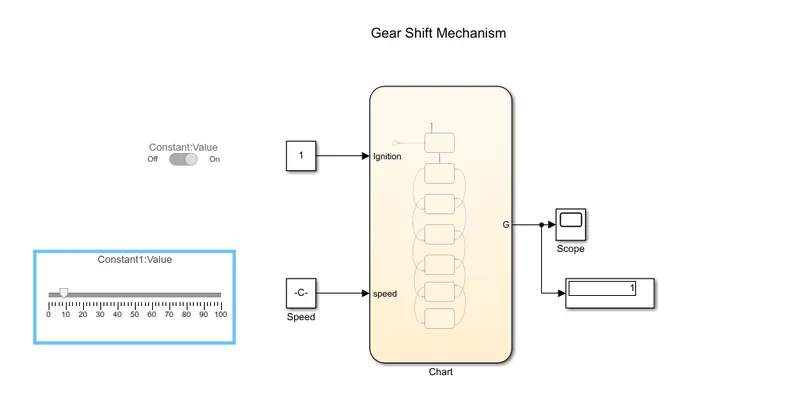
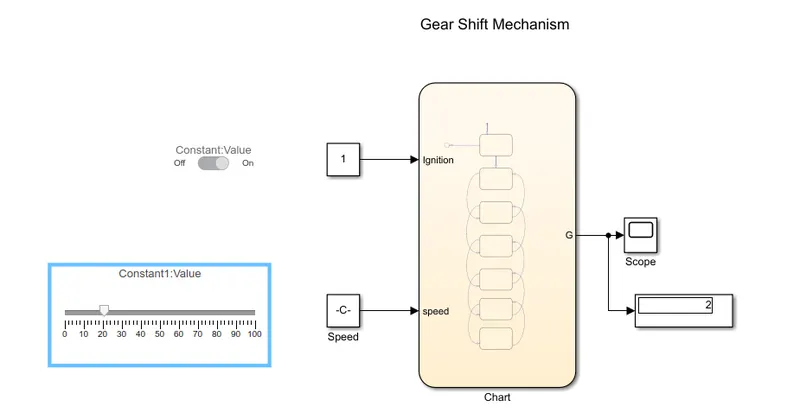
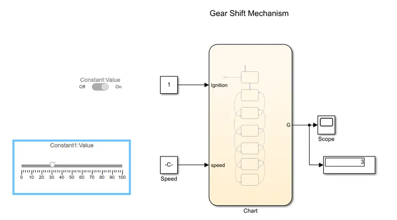
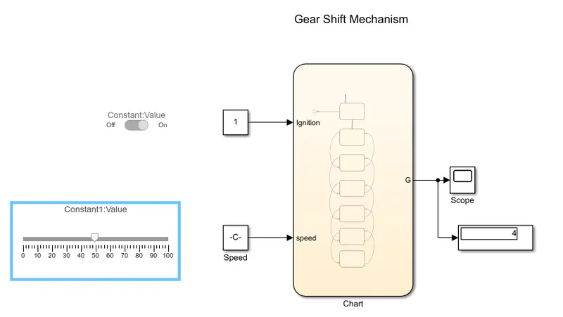
- A slider block is connected constant block to define speed to change the speed during simulation is running, hence it acts as input speed.
- A constant block connected with slider switch to provide define Ignition.
- A constant block is connected to slider gain to provide the initial input.
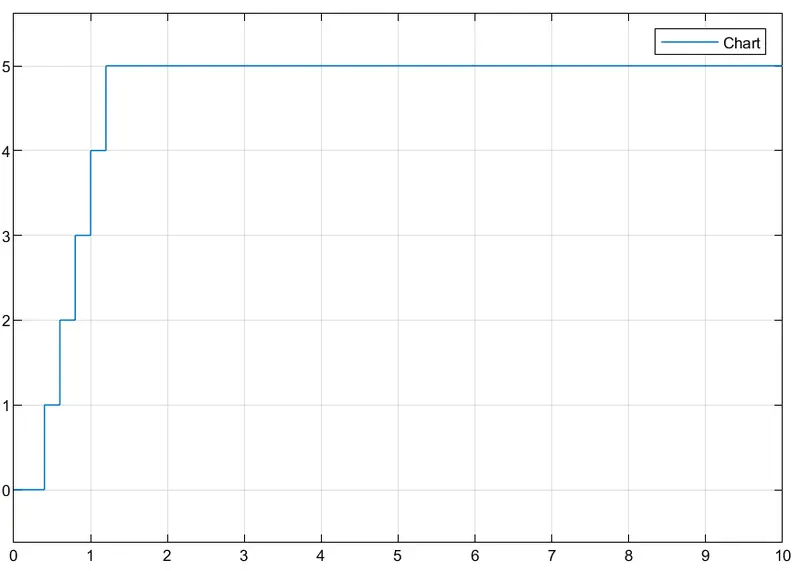
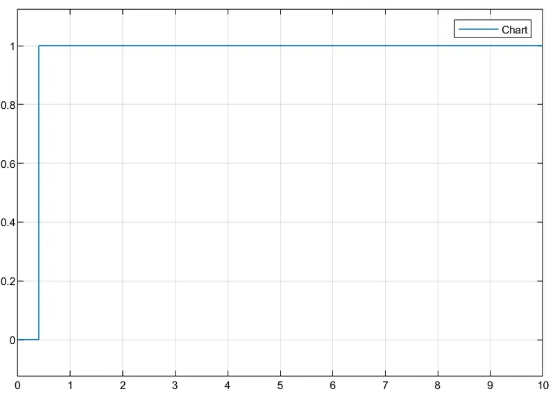
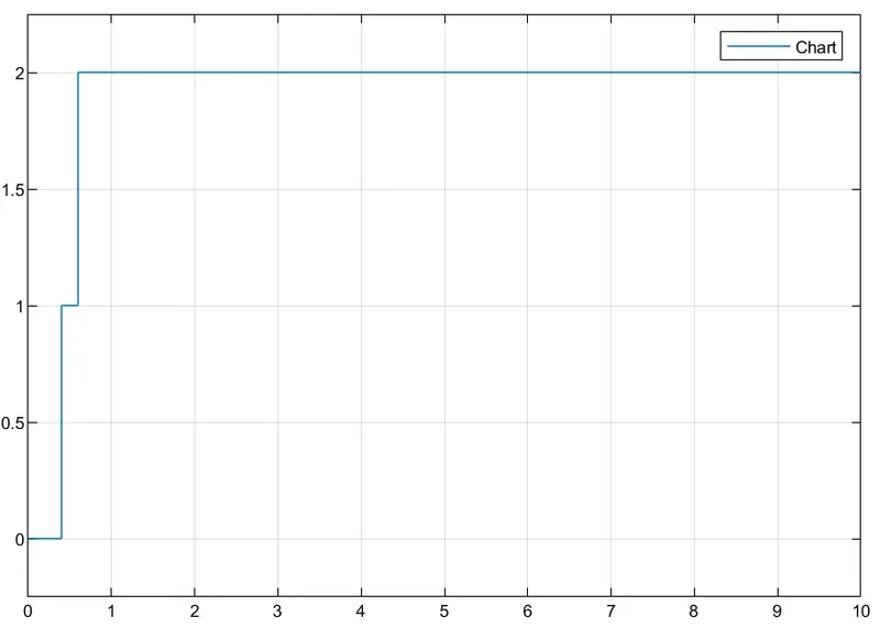
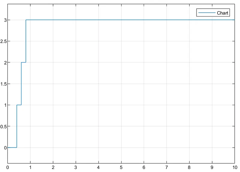
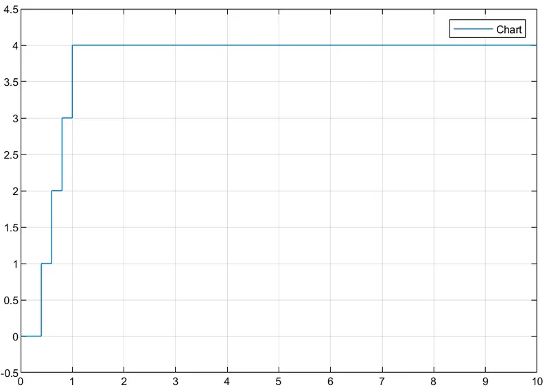
- A scope is connected to port G inorder to see the gear switching according to different speed conditions provided. When the speed is changed using slider, it will show the respective gear shift in scope.
- A Display block is connected to see the gear number at different speed range.
Simulink Model for Gear shift mechanism:
Control Logic Structure:
Speed: 0 to 15kmph, Gear, G=1:
Speed: 15 to 25 kmph, Gear, G=2:
Speed: 25 to 40kmph, Gear, G=3:
Speed: 40 to 60 kmph, Gear, G=4:
Speed: Greater than 60kmph, Gear, G=5: