Week - 4
Task 1 - Washing Machine
Aim:- To implement Control Logic of a Washing Machine that would function as follows:-
- If the power supply is available, the system gets activated
- If the Water supply is not available, stop the process & indicate through LED
- Soaking time should be 200s followed by Washing time of 100s.
- Then rinsing happens for next 20s & dryer runs for 50s
Modelling-
1. Chart Element for control logic
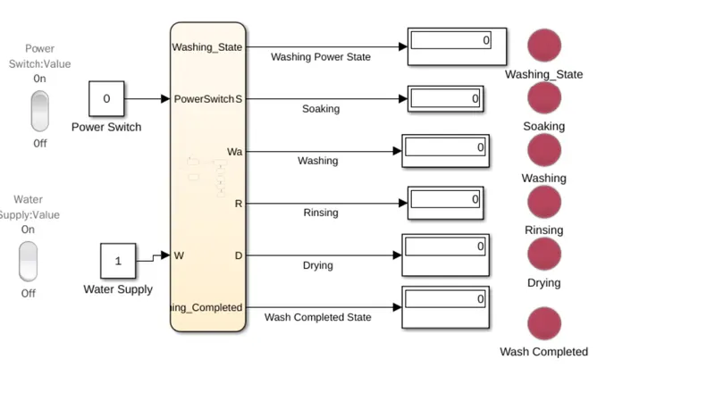
Components of the model
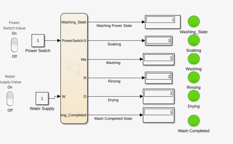
1. Rocker Switch- These are switches that determine Power ON/OFF and Water ON/OFF. A Value 0 indicates OFF condition and 1 indicates on condition.
2. Chart Element- The detailed control logic of the washing machine is implemented in the chart element.
3. Lamp. Lamps are used to indicates status. Green indicates "Completion" and Red indicates Incomplete status.
Results:-
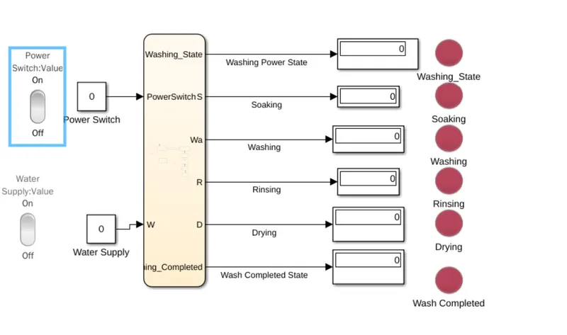
1. Power OFF Condition (State 0):-This state would result in washing machine remaining in OFF condition.
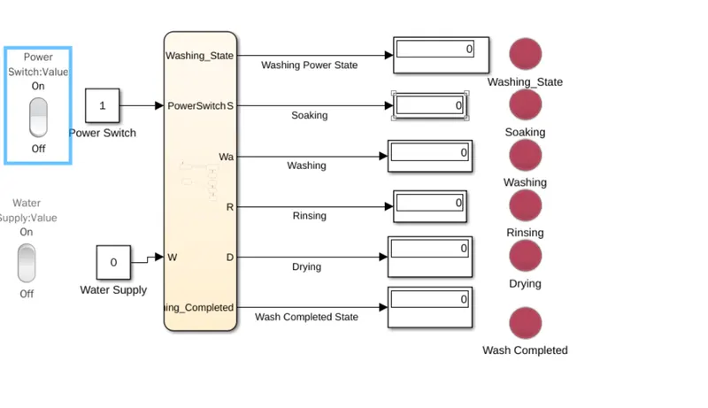
2. Power ON but Water OFF:- This again would result in processes being incomplete.
3. Power and Water both available:-
- Machine ON
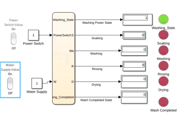
- Soaking Completed
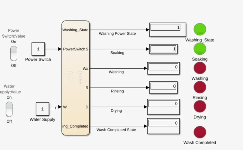
-Washing
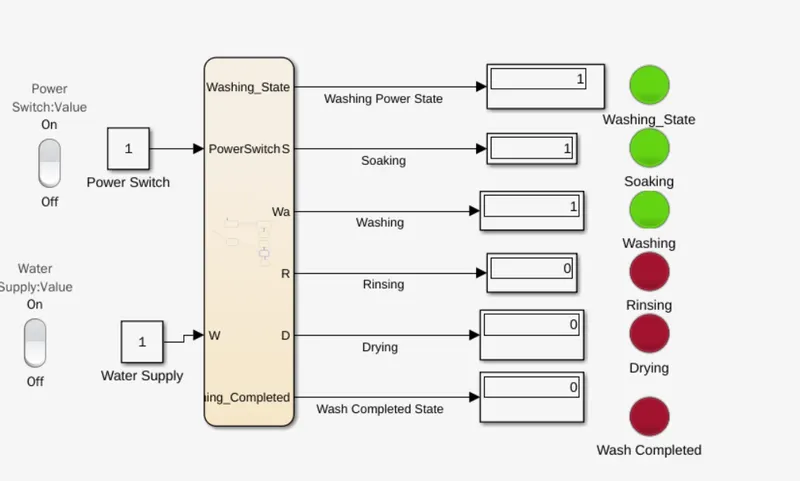
-Rinsing
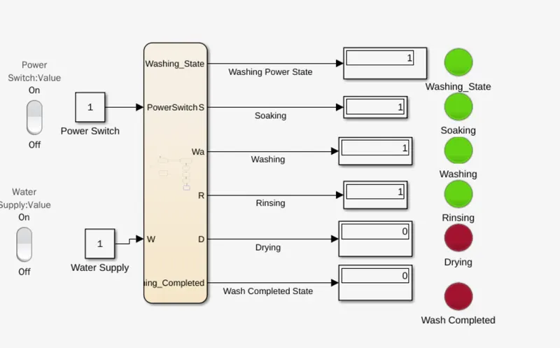
- Drying and Wash Complete
Task 2
Aim:- To create a Gear Shift logic as per the below criteria
Speed Range(kmph) Gear
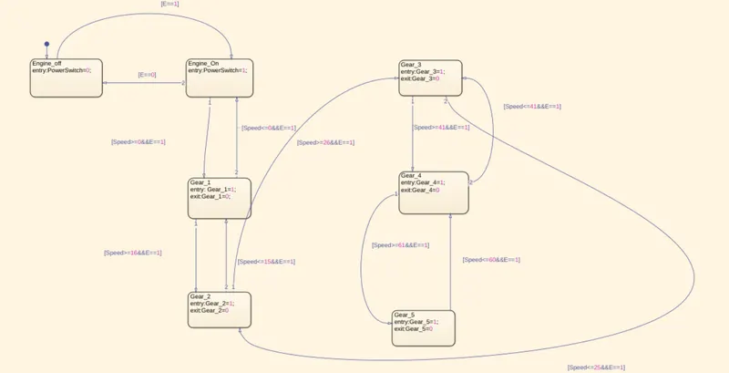
0 to 15 1
16 to 25 2
26 to 40 3
41 to 60 4
Above 61 5
Model
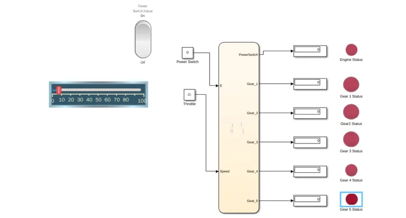
Components
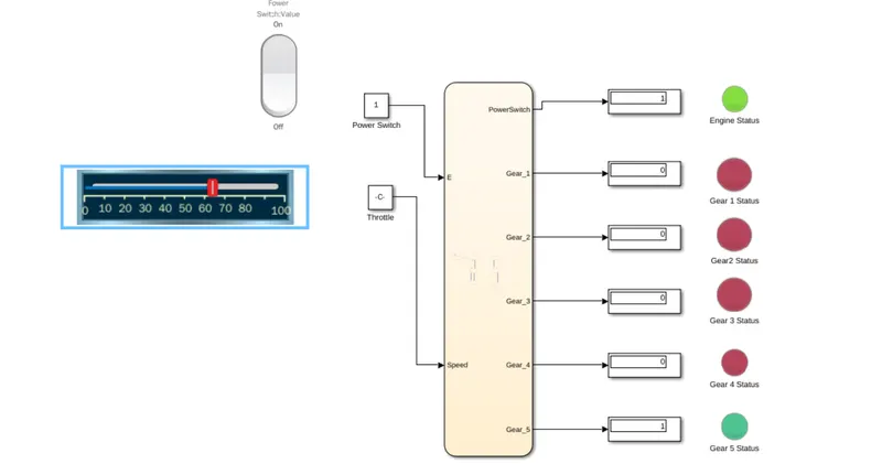
1. Rocker Switch- This block is used to indicate Engine on or OFF.
2. Horizontal Slider- This block is used to set the speed of the vehicle
3. Chart- Used to implement the control logic. In this example it is used to implement gear control logic.
4. Lamp- Used to indicate which gear is in use. Green indicates the concerned gear is in use. Red in dicates the concerned gear is disengaged. Also used to indicate Engine ON/OFF.
Results.
1. Engine OFF:- Vehicle Stationary
2. Engine On and Speed 0-15- Gear 1 engaged
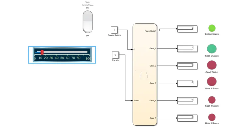
3. Engine On and Speed 16-25- Gear 2 engaged
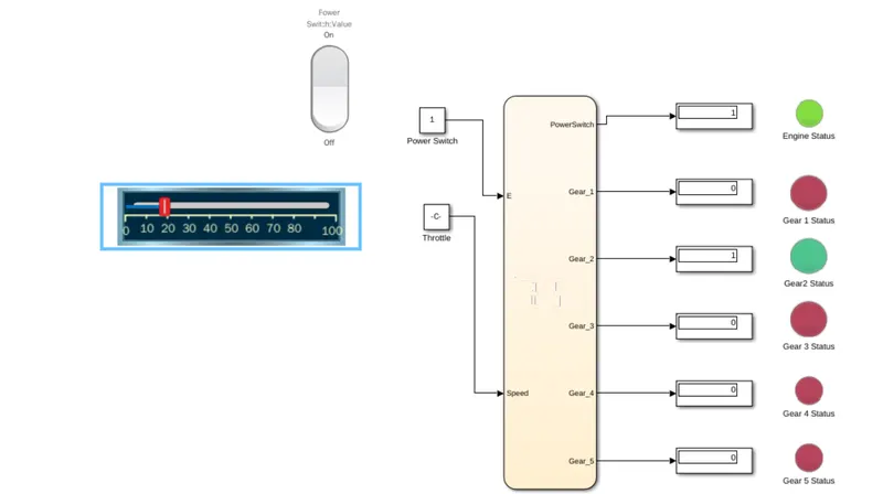
4. Engine On and Speed 26-40- Gear 3 engaged
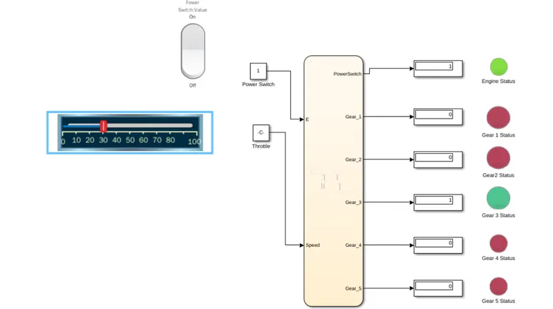
5. Engine On and Speed 41-60- Gear 4 engaged
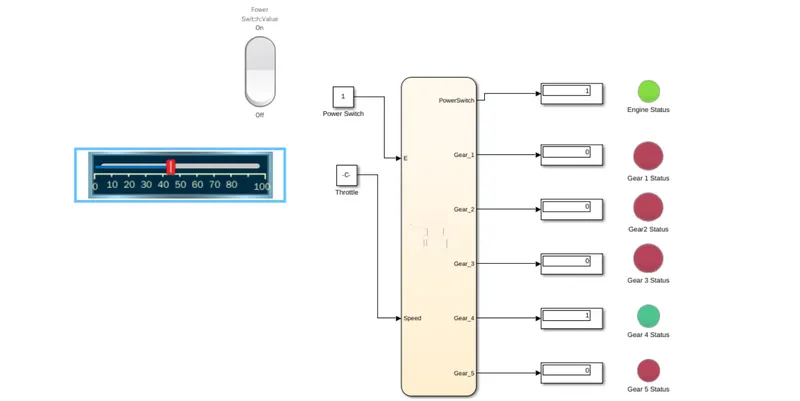
6. 5. Engine On and Speed above 61- Gear 5 engaged