Week-11 : Discretization of 3D intake manifold using GEM-3D
Part 1.
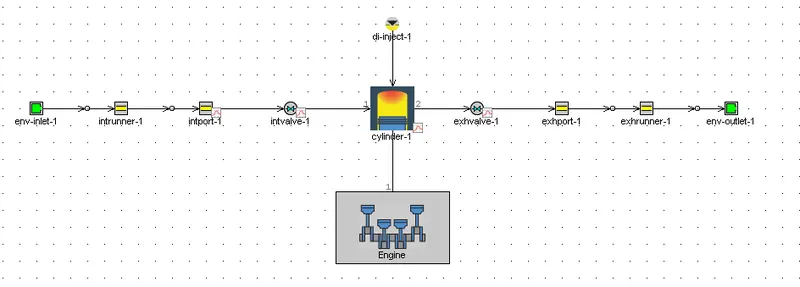
1) The study is done on a single cylinder diesel engine
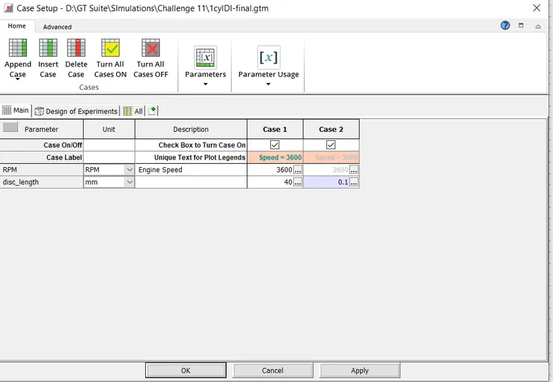
Discretization length :
Specifies the length of each sub volume where quantities are calculated (Pressure, temperature, mass fractions etc)
There are two case setup namely 40mm and 0.1mm
Comparison of results
We analyse the results from two cases
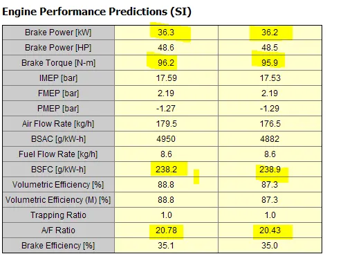
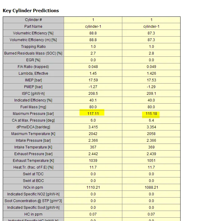
From the above highlighted values, it is noted that the difference in technical parameters such as Brake Poewer, torque, BSFC and Maximum Pressure is comparable, i.e difference is very small.
Comparison of SImulation Time
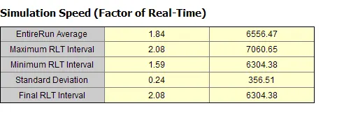
The time taken in case 2 where the discretization length is 0.1 mm is significantly larger, of the order of 6566. Discretization improves accuracy but increases simulation time.
Tutorial 2
1. Separating Section by curves
Need to remove caps so the ends are open and available for flow. Separate geometry based on changes in the surface of the object. ALso separates intake runners into two different sections near the area change at the top of the runners. Part selected, Separate by curves chosen from SHape operations group in the Convert Tab.
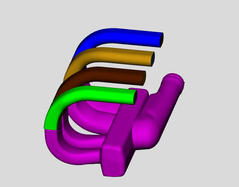
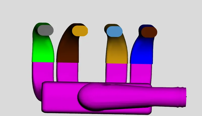
- End caps are removed to facilitate flow. 4 Cylinder endcaps and one intake end caps are removed
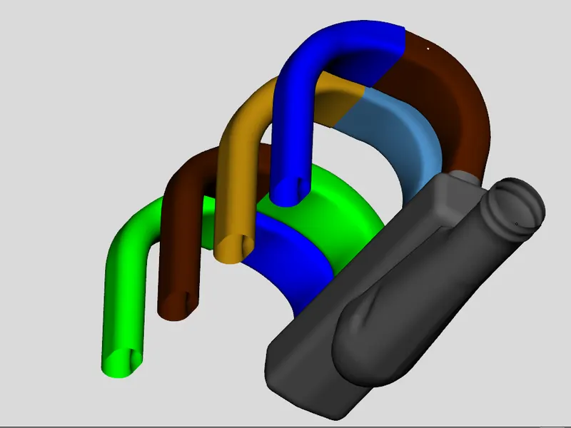
2. Use of Cutting Plane to separate 4 runners from the manifold.
3 point cutting plane is selceted. Three points on the underside of the manifold are chosen. After the third point is chosen the current position of the cutting plane is shown. We translate the cutting plane away from the manifold enough to cut just the runners.
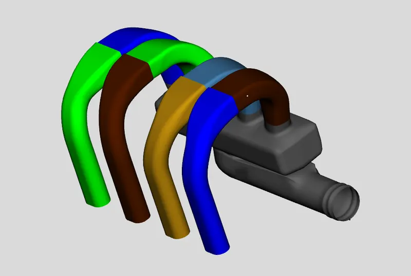
3.Selection of Mesh shape that is to be cut in the graphical windows.
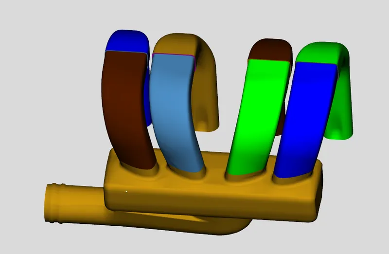
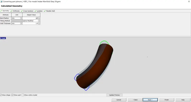
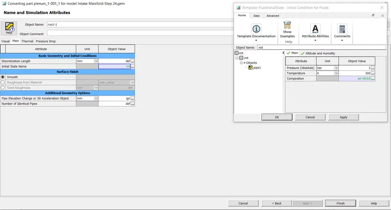
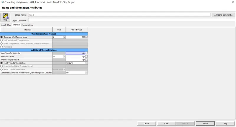
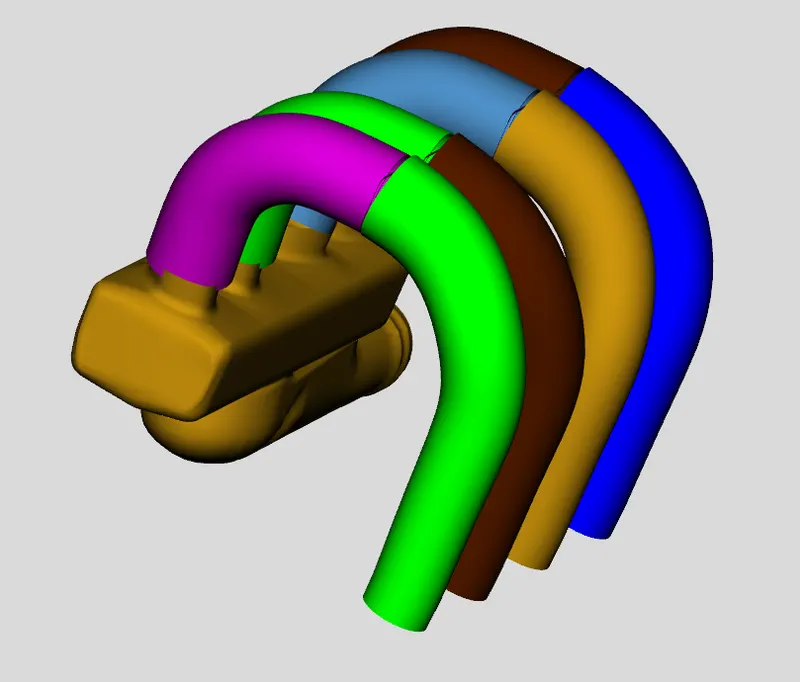
4.Converting Sections into Flow Components
- Intake runner
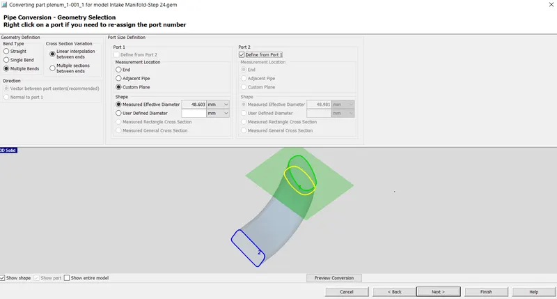
5.Adding a Custom connection
In the conversion process for the runners, information regarding the curved entry from the manifold was lost. Curved entry would represent a better flow transition than a default orific connection so need to manually add an orifice connection to represent this.
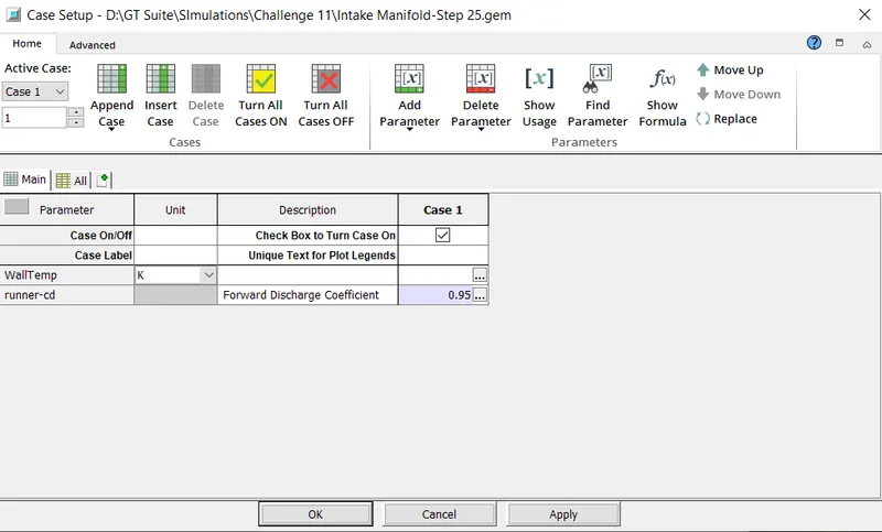
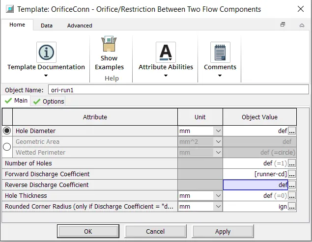
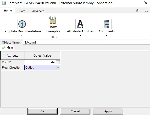
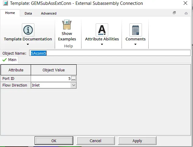
6.Adding a sub assembly connection to impose a connection direction
The next step is to specify the end boundary connections ie the connections which do not connect to anything. The ends of each runner need an end connection specified. Done with a sub assembly connections.
Port 2 is selected and the sub assembly connection "GEMSubASSEXTConn is selected.
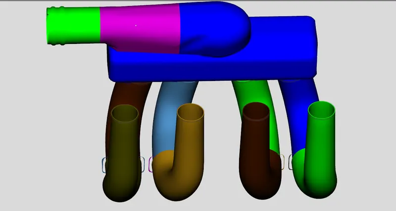
7.Dividing Pipe Sections with Area Changes
Using Pipe Normal Cutting Plane operation, cutting plane is placed to separate the circular outer region followed by subsequent inner region.
8.Conversion of part to flow component
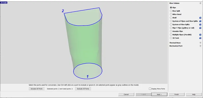
9.Separate the Manifold from the 90 degree flowsplit
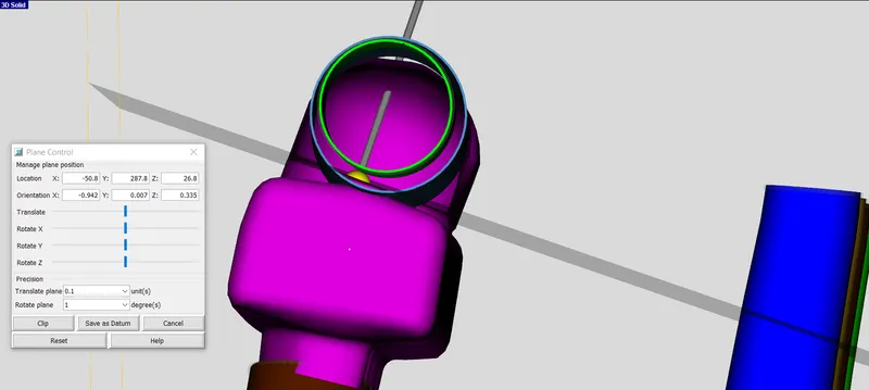
The aim of this operation is to cut off the top flowsplit section without cutting through the manifold itself. 3 Points Cutting plane from cutting plane group in Convert tab is used.
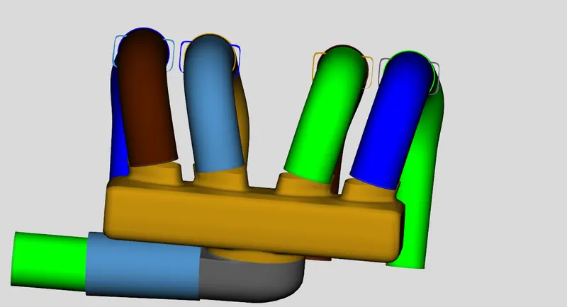
10.Converting Sections into general Flow splits
This procedure is done to convert the entrance to the manifold into flow component. Flowsplit is used for conversion process.
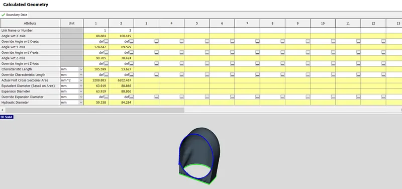
11.Dividing the Intake volume into smaller sections.
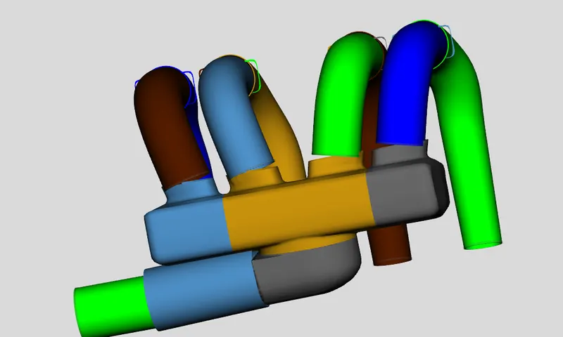
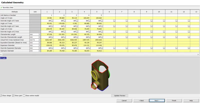
12.Conversion on manifold into flow components
-Edge Manifolds (Flow splits)
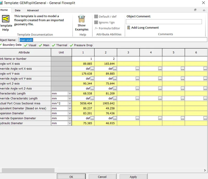
Center Manifold
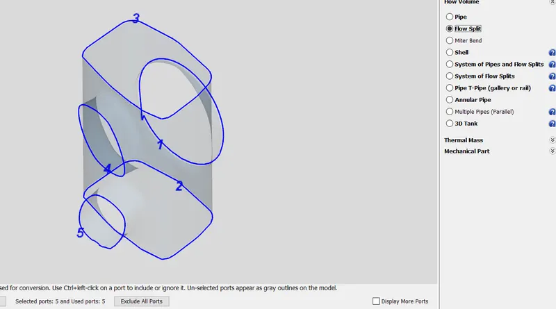
14.Adding Flow Connections
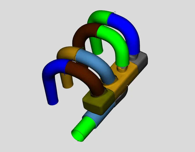
Using flow connection option the gaps in the geomtry are sealed. Between manifold and exhaust, "Extruded connection option was chosen.
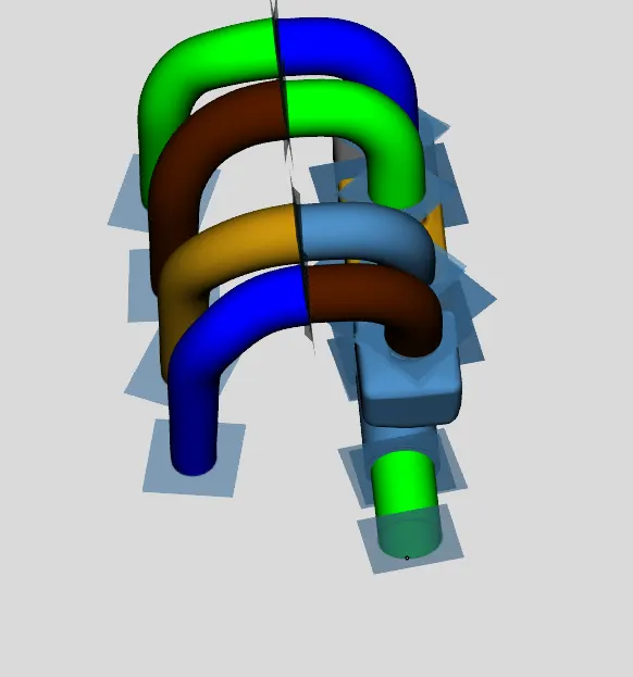
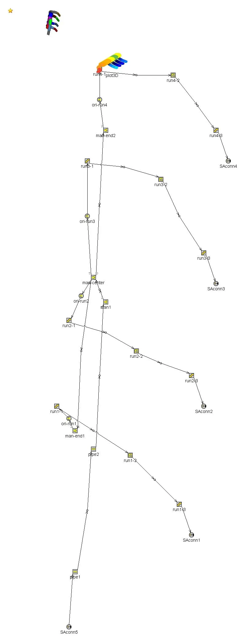
15. Final Discretized model