Week - 4
Objective
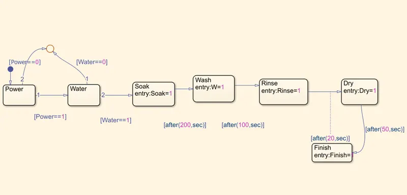
To Implement control logic of a “washing machine” using Stateflow as per given sequence:
-If the power supply is available, the system gets activated
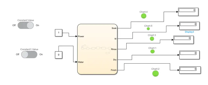
-If the Water supply is not available, stop the process & indicate through LED
-Soaking time should be 200s followed by Washing time of 100s.
-Then rinsing happens for next 20s & dryer runs for 50s
-After all the processes have completed turn on the finished LED.
Stateflow
Stateflow is a graphical language which includes state transition diagram, state transition table, truth tables and flowchart. It shows how matlab and simulink model responds to the input signal, events and time dependent factors. Stateflow alloes to design and develop the supervisory control, task scheduling, fault management , communication protocol, hybrid system and user interface. It also allows to debug and analyze the logic during execution.
Control Logic
It is the most important part of any software program which controls its operations. It respond to the command given by the user and also perform automated task that is structured into the program. control logic is modelled with the help of state diagram.
Theory
washing machine is a home appliances used to wash laundry. the term is mostly applied to machine that use water as oppose to dry cleaning and ultrasonic cleaner. the detergent can be in liquid or powdered fprm.
Procedure
1. Create a chart for defining the stateflow.
2. Circular juction is to terminate the signal flow and return to null value.
3. If power is off '0' then process is terminated at the junction or else '1' is considered.
4. If water is off'0' then process is terminated at the junction or else'1' is considered.
5. Now thw soak block is activated and soaking of clothes takes place.
6. After 200 seconds of soaking, wash block becomes active and washing takes place.
7. After 100 second of washing , Rinse block gets activated and Rinsing takes place.
8. After 20 second of rinsing, dry block gets activated and clothes are being dried in this step.
9. After 50 second of dry , Finish blocks gets activated. finish block terminate the signal flow in the chart.
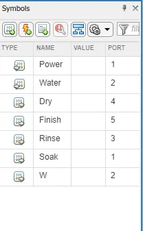
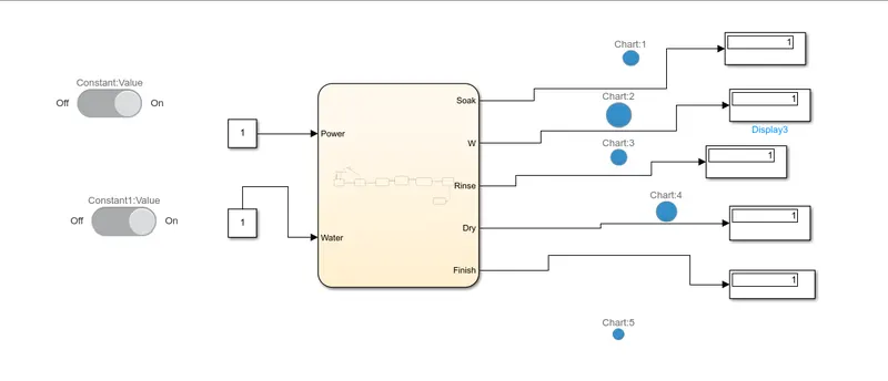
10. Now connect the power and water as input and wash, soak, rinse, dry as output.
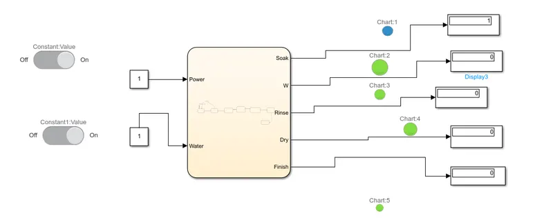
11. connect constant to power and water block. inputs are connected to slider and toggle . Lamp are connected to observe on/off position.
12. common scope is connected to entire washing and connected to all output ports.
Stateflow model
symbols
Power on, Water off
Power on , Water on , t= 10 sec
Power on, Water on, t = 500 sec
Conclusion
From the above stateflow diagram basic operation of washing machine is understood.
2. Objective
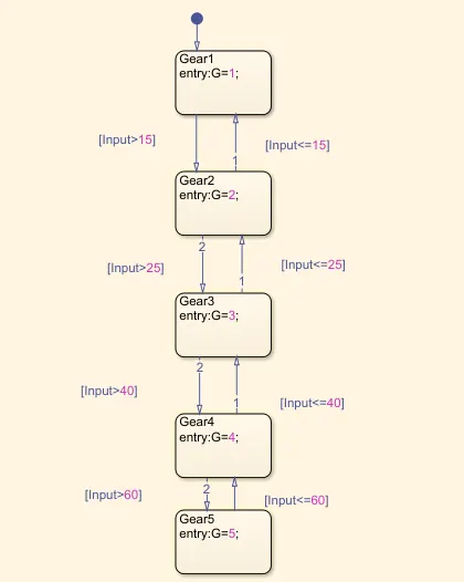
Make a Simulink chart for the “Gear shift” logic as per below conditions:
Speed Range(kmph) Gear
0 to 15 1
16 to 25 2
26 to 40 3
41 to 60 4
Above 61 5
Give speed input while the simulation is running & display the gear number.
Theory
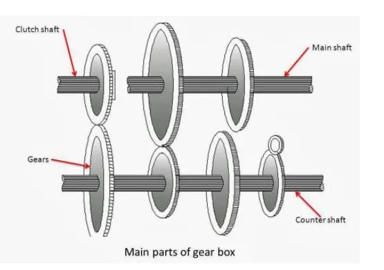
Gearbox and gearheads also called gear reducer or speed reducer are power transmission device that uses gear arrangement in an enclosed housing to transfer energy, increase torque and reduces the speed from one device to another. This transmission box changes the engine speed into torque while hill climbing. also called torque converter.
Basic function of geraboxIt provide the torque needed to move the vehicle under different road condition by changing the gear ratio between the engine crankshaft and driving wheel.
- it shifted to reverse direction so that vehicle can move forward.
- it shifted to neutral for engine starting
Working
Gearbox facilitates the control of slow and fast behaviour of vehicle.
It transmitt the torque and engine speed according to the demand.
It broadens the limited speed and torque behaviour of internal combustion engine to bigger scale.
It gives relative movement between engine and driving wheels due to flexing of road spring.
It also provide the leverage between the engine and the driving wheel to be varied.
Stateflow Procedure
1. create a chart for defining the stateflow
2. If ignition is off '0' , the process is terminated else 1 is carry forwarded.
3. If speed is less than equal to 0 the flow is terminated and gear 0 is activated, else 1 is carry forwarded.
4. If speed is greater than 0 and less than equal to 15, flow is terminated and gear 1 is activated.
5. If speed is greater than 15 and less than equal to 25, the flow is terminated and gear 2 is activated.
6. If speed is greater than 25 and less than or equal to40, the flow is terminated and gear 3 is activated.
7.if speed is greater than 40 and less than or equal to 60, the flow is terminated and gear 4 is activated.
8. If speed is greater than 60, the flow is terminated and gear 5 is activated.
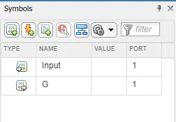
9. Define ignition and speed as input where as speedometer, scope as output.
10. A common scope is connected to observe the speed numerically.
Stateflow Model
Symbols
Simulink Model
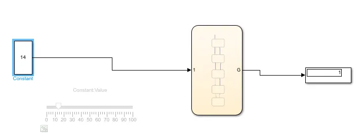
Input speed 14 kmph, Output Gear 1
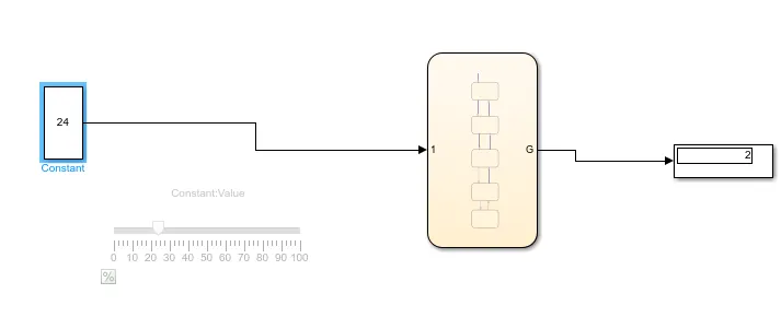
Input Speed 24kmph, Gear 2
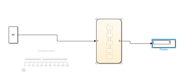
Input Speed 40kmph, Gear 3
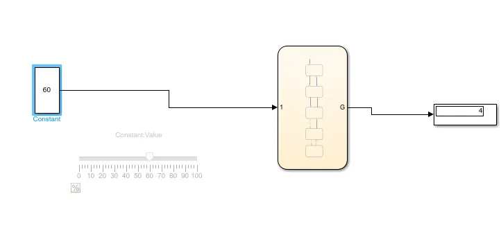
Input Speed 60kmph, Gear 4
Conclusion
From the above stateflow model Gearshift mechanism is understood.