Week-7 Challenge: DC Motor Control
1. A. Explain a MATLAB demo model named ‘Speed control of a DC motor using BJT H-bridge’.
BJT
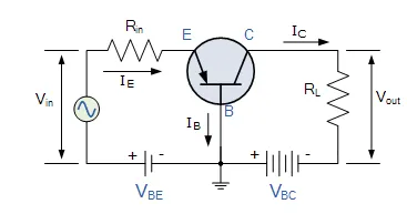
The Bipolar Junction Transistor is a semiconductor device which can be used for switching or amplification. The two diodes produces a three layer, two junction, three terminal device forming the basis of a Bipolar Junction Transistor, or BJT for short.
Transistors are three terminal active devices made from different semiconductor materials that can act as either an insulator or a conductor by the application of a small signal voltage. The transistor’s ability to change between these two states enables it to have two basic functions: “switching” (digital electronics) or “amplification” (analogue electronics). Then bipolar transistors have the ability to operate within three different regions:
- Active Region – the transistor operates as an amplifier and Ic = β*Ib
- Saturation – the transistor is “Fully-ON” operating as a switch and Ic = I(saturation)
- Cut-off – the transistor is “Fully-OFF” operating as a switch and Ic = 0
Bipolar Transistors are current regulating devices that control the amount of current flowing through them from the Emitter to the Collector terminals in proportion to the amount of biasing voltage applied to their base terminal, thus acting like a current-controlled switch. As a small current flowing into the base terminal controls a much larger collector current forming the basis of transistor action.
The principle of operation of the two transistor types PNP and NPN, is exactly the same the only difference being in their biasing and the polarity of the power supply for each type.
IGBT
Insulated Gate Bipolar transistor
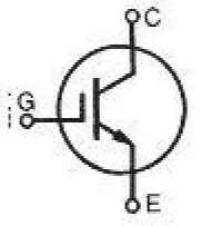
The insulated gate bipolar transistor IGBT">IGBTIGBT is a semiconductor device with three terminals and is used mainly as an electronic switch. It is characterized by fast switching and high efficiency, which makes it a necessary component in modern appliances such as lamp ballasts, electric cars and variable frequency drives VFDs">VFDsVFDs.
Its ability to turn on and off, rapidly, makes it applicable in amplifiers to process complex wave-patterns with pulse width modulation. IGBT combines the characteristics of MOSFETs and BJTs to attain high current and low saturation voltage capacity respectively. It integrates an isolated gate using FET (Fieldeffecttransistor">Fieldeffecttransistor). Fieldeffecttransistor to obtain a control input.
IGBT Symbol
Principle
IGBT requires only a small voltage to maintain conduction in the device unlike in BJT. The IGBT is a unidirectional device, that is, it can only switch ON in the forward direction. This means current flows from the collector to the emitter unlike in MOSFETs, which are bi-directional.
Applications of IGBT
The IGBT is used in medium to ultra-high power applications, for example traction motor. In large IGBT, it is possible to handle high current in the range of hundred amperes and blocking voltages of up to 6kv.
IGBTs are also used in power electronic devices such as converters, inverters and other appliances where the need for solid state switching is necessary. Bipolars are available with high current and voltage. However, their switching speeds are low. On the contrary, MOSFETs have high switching speeds although they are expensive.
Matlab model of BJT H bridge ckt
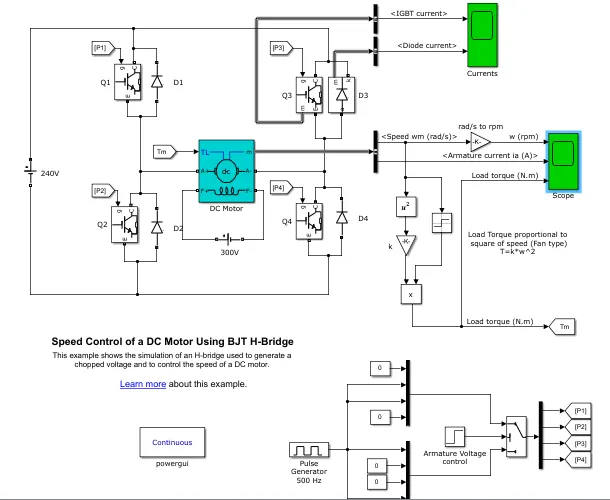
Fig Simulink model for BJT H bridge
Major Blocks
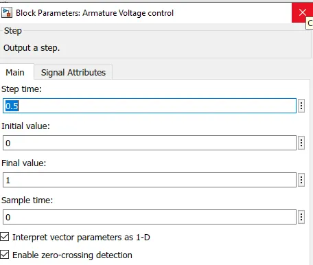
Pulse generator- It is used to generate the pulse which use to drive the gate pulse of transistor. Amplitude of pulse generator is 1 , time period is 0.002 sec, pulse width is 75 %'
Here we are using four IGBT with four diodes connected in pairs . these transistor is operated simultaneously like Q1 and Q4 are made on which gives positive voltage to motor and the motor drives in positive forward direction. If Q1 and Q2 are made on then network creates low resistance path and it becomes short circuited, so it is prefer to switch on Q1 and Q4. In the next operating mode Q2 and Q3 is made on which gives negative voltage to motor and motor drives in reverse direction in order to continously rotate the motor. Here D1 D2 D3 D4 act as free wheeling in their respective switching mode . As this IGBT arrangement is in H shape so it is called as H bridge circuit.
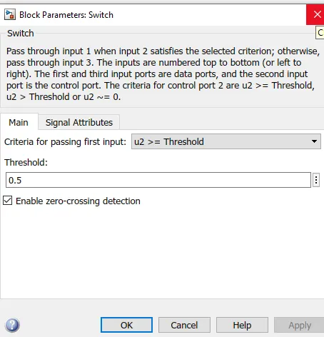
here we are using switch block for controlling the IGBT. The switch block is controlled by the pulse generator
Results
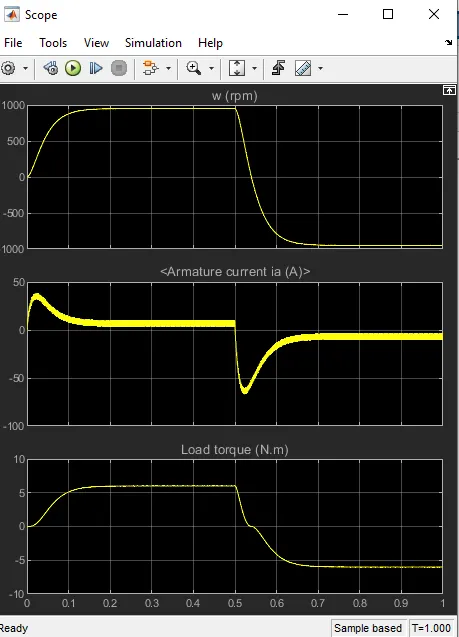
The sudden rise and fall of armature current is due to change is operating mode of motor forward to backward direction.
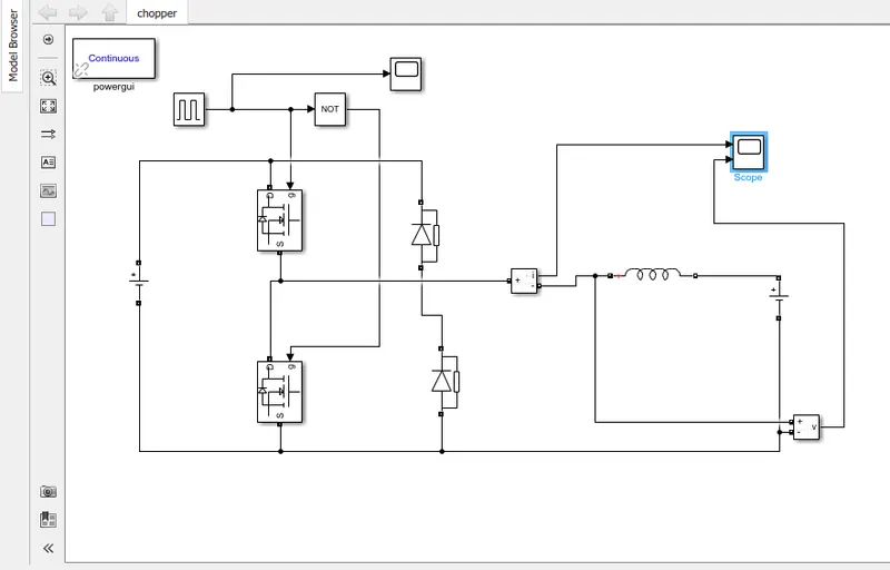
3.Develop a 2-quadrant chopper using simulink & explain the working of the same with the relevant results
Matlab model
pulse generator rating
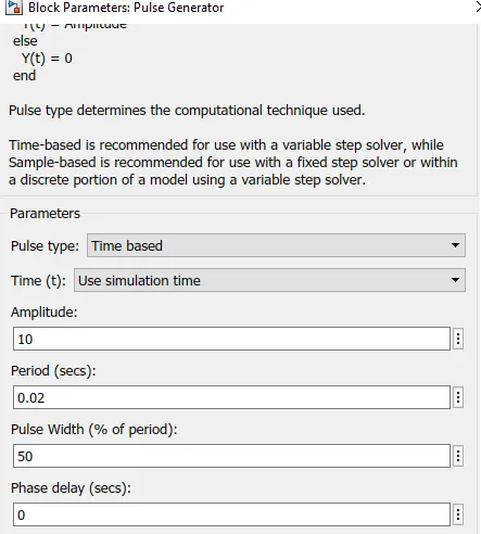
dc voltage 1 is set to 24 volta and dc voltage 2 is set to 12 volts.
All the connection are made as per the model. The simulation is run for 1 sec.
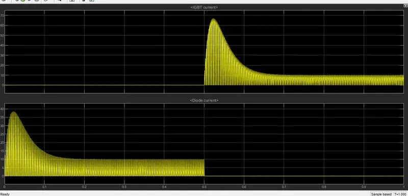
Results
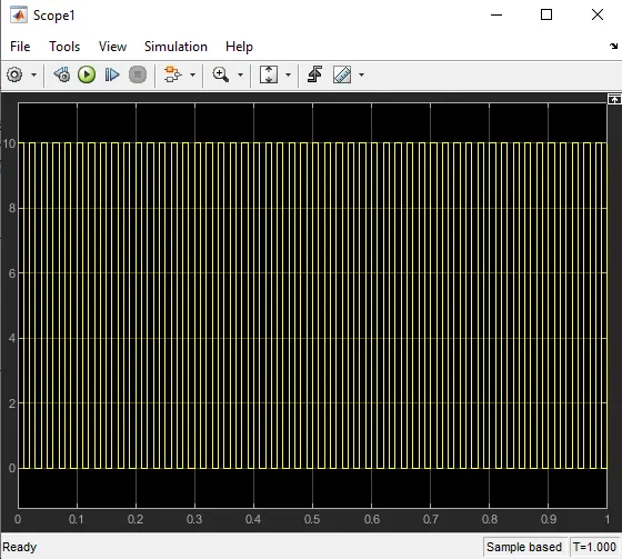
pulse generator output
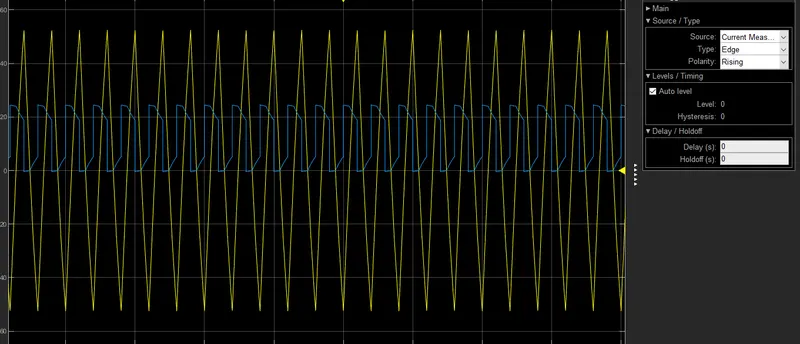
voltage and current waveform
3. Explain in a brief about operation of BLDC motor.
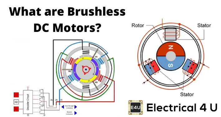
A brushless DC motor (also known as a BLDC motor or BL motor) is an electronically commuted DC motor which does not have brushes. The controller provides pulses of current to the motor windings which control the speed and torque of the synchronous motor.
These types of motors are highly efficient in producing a large amount of torque over a vast speed range. In brushless motors, permanent magnets rotate around a fixed armature and overcome the problem of connecting current to the armature. Commutation with electronics has a large scope of capabilities and flexibility. They are known for smooth operation and holding torque when stationary.
Brushless DC motor has only two basic parts: rotor and the stator. The rotor is the rotating part and has rotor magnets whereas stator is the stationary part and contains stator windings. In BLDC permanent magnets are attached in the rotor and move the electromagnets to the stator. The high power transistors are used to activate electromagnets for the shaft turns. The controller performs power distribution by using a solid-state circuit.