Week -2
Objective
To create simulink model of door bell using solenoid block-
a) Electrical phenomena of door bell for production of sound.
b) Observation of physical movement of plunger when switch is closed for two second and realeased.
c) Analysis of output reasult.
Given Diagram
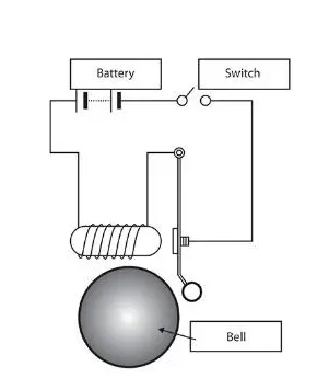
Solenoid
Solenoid is type of electromagnet whish is used to generate a controlled magnetic field through a coil wound into a tightly packd helix. Its length is large as compared to its radius and each turn is taken as closed circular loop. The magnetic field generated is equivalent to the field generated by circular loop.the total magnetic fild is given by the vector sum of force generated by each turn.
Blocks used in model
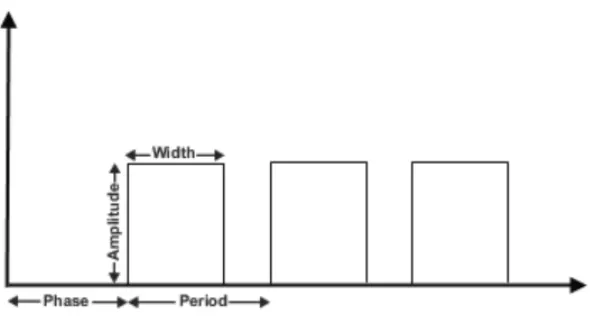
Pulse generator
This block generate square wave pulse at regular interval of time. Various factor affecting the waveform are like amplitude , pulse width, phase delay and period.
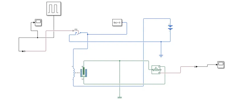
Simulink ps convertor- This convertor used to convert simulink signal to physical signal.
Battery- This gives electrical input voltage to the system.
Switch- This switch is modulated by external physical signal. If the physical signal is grater than the reference signal, then switch is in closed position otherwise open.
Solenoid- This blocks presents the position of plunger corresponding to the induced EMF. The spring constant always set to be zero.
Electrical and Mechanical references- This provides frame of reference to the respective blocks. Both must be connected directly to the ground.
Solver Configuration- Physical network connected by simscape block requires a solver information setting for simulation.
Ideal Translational Motion Sensor- This device measures the velocity and displacement in mechanical translational network. the signal V and P port are for velocity and position respectively.R port is relative to port C. The measured velocity is positive when velocity of R port is greater than the velicity of C port.
Scope- To view the input and output characteristics of the signal.
Simulink Model
Results
Situation when switch is closed for 2 second and then release.
Input Signal
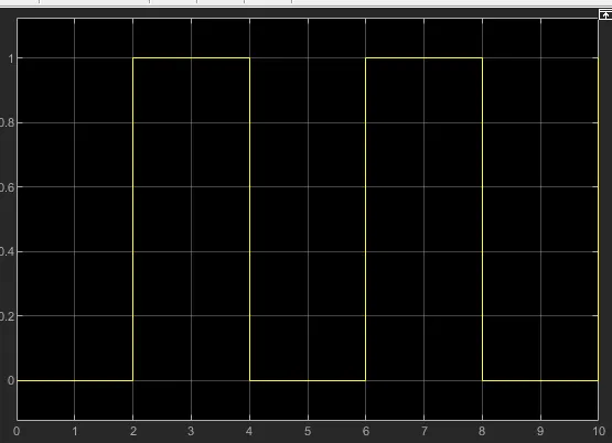
Output wavwform
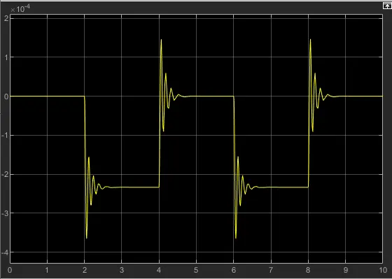
The above result is obtained with following parameters of pulse Generator.
Amplitude 1
Period - 4
Pulse width 50
Phase Delay 2
Damping is observed due to solenoids damping parameter. The wavwform is positive because the motion direction is set . port R away from Port C.
Conclusion-
The physical movement of plunger is observed when switch is closed for two second and understand the basic principle , construction and working of doorbell in simulink domain.
2) OBJECTIVE - Use of Thermistor to sense a temperature of a heater and turn on/ off fans as per condition
Conditions
a) 20 degree for 0 to 10 seconds
b) 27 degree for 10 to 30 seconds
c) 23 degree for 30 to 50 seconds
THERMISTOR
It is type of resistor whose resistance is strogly dependent on the temperature. It act as passive component to the circuit. They are accurate , cheap and robust in way of temperature measurement.
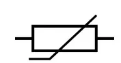
Symbol-

Uses
Thermistor is used in variety of appications.
1. Digital Thermometer
2. Automotive Application
3. Circuit Protection
4. Rechargable Batteries
5. To measure the thermal conductivity of material.
WORKING
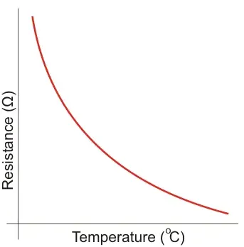
The basic principle is that its resistance is dependent on the temperature and one can measure its resistance with ohmmeter. The relationship between thermistor's resistance and temperature is nonlinear.
There are two types of Thermistor
1) Negative Temperature coefficient(NTC)
2) Positive Temperature Coefficient( PTC)
NTC Thermistor
In this type, the resistance decreases with increase in temperature and vice versa. They are most common type of Thermistor.
Mathematical Formula
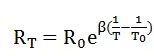
where
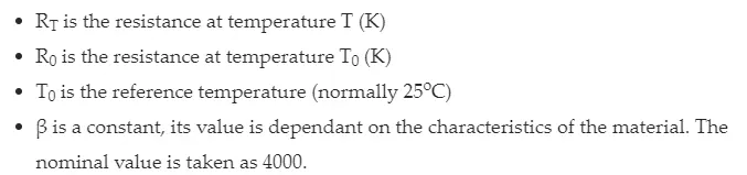
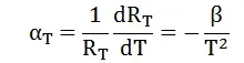
For good performance , β value should be high. For higher value of β means large variation in resistance for the same rise in temperature. Hence the resistance temperature coefficient is given by
PTC Thermistor
Here in this type of thermistor , resistance directly depends upon the temperature. As temperature increases resistance also increases. They are not common as NTC thermistor, but mainly used in the protection of circuit.
Simulink Model
Blocks Used
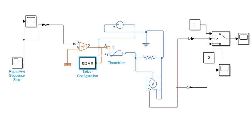
Repeating sequence stair,thermistor, simulink ps convertor, voltage Source, Switch, constant, scope, ps simulink convertor,solver configuration, controlled temperature source.
The above model is fed by repeating sequence stair as a input signal and temperature is to be maintained as following
20 degree for 0 to 10 sec
27 degree for 10 to 30 sec
23 degree for 30 to 50 sec
Fan is in on condition if temp is above 25 degree otherwise off.
Repeating Sequence Block
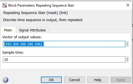
The repeating sequence is connected to the simulink ps converter which is followed by controlled temperature source. scope is also connected to the sequence stair.
The S port of controlled temperature source is connected to the simulink ps conveter and A port to thermal resistance. The thermistor block consist of variable window where the priority level is set to low.
The resistance is placed parallel to voltage sensor block is taken to be 1 ohm.The lectrical circuit is grounded with the electrical reference. The centre of the switch is connected to the PS simulink conveter and rest two are conected with constant 1 and constant 2.
The switch block operates on IF ELSE logic. If the value is above threshold level then output is given as 1 and if value is below the threshold point the value is given as 0. After modelling, the simulation is run for 50 sec and waveform is obtained.
Input Signal
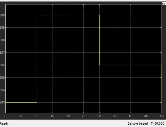
Output Signal
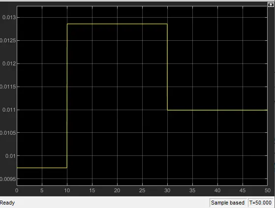
ON /OFF phenomena by IF ELSE logic
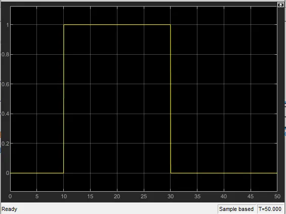
The above graph shows the fan is turned on for 10 to 30 second when temperature is above 296 kelvin otherwise off.
Conclusion
Simulink model of thermistor is created with fan on / off based condition which depends upon the temperature and time.