Project-1: Modelling an electric Car with Li-ion battery
Objective
Create a MATLAB model of electric car which uses lithium ion battery and suitable motor. Choose suitable blocks from Simscape or Powertrain block set. Implement the vehicle speed control using PI controller and generate brake and accelerator commands. Avoid using readymade driver block for speed control.
Theory of Lithium ion battery based Electric Vehicle

Main components of an Electric Vehicle (EV):
The main components of an electric vehicle system are as below:
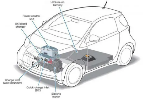
- Electric Battery: Battery stores the electricity required to run the vehicle. The battery supplies electric current to the motor. And thus, the vehicle runs. The higher the capacity of the battery the higher is the range of the electric vehicle. Most modern electric vehicles use Lithium-ion type batteries. These batteries have higher energy density. It means they are capable of storing more energy.
- Inverter: battery stores the electric current in the form of Direct Current (DC). But, the majority of the motors used in the electric vehicles run on Alternating Current (AC). So, the inverter performs the function of converting DC to AC.
- Electric Motor: An electric motor provides the power to rotate the wheels. Motors may be of DC/AC type. However, the AC motors are more common.
- Regenerative Braking Energy: The electric-vehicle has only limited energy available. Hence, you need to save every bit of it. This system recovers the energy lost in braking the vehicle and utilizes it to charge the batteries.
- Power Control Unit: The control unit performs the main task. It controls the activities of all the components of an electric vehicle. It monitors the output of the motor, charging of batteries. Also, it provides the necessary information to the driver.
Advantages of using an Electric vehicle:
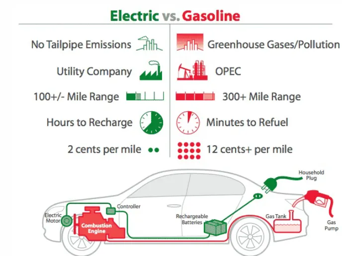
Electric vs Gasoline
- Less air pollution: There is an absence of any combustion process. Hence, these vehicles do not emit polluting gases into the atmosphere. So, they cause less harm to environment compared to traditional IC engine powered vehicles.
- Less noise pollution: The electric motor runs quietly. Hence, the noise level while operating these vehicles is much lower than that of the petrol or deisel engine powered cars. Thus, it results in very less noise pollution.
- Higher efficiency: The efficiency of operation of an electric vehicle is much higher. For e.g. the efficiency of an electric motor is nearly 90% compared to an Internal combustion engine. Hence, in all, an electric-vehicle is more efficient than petrol or Diesel vehicle.
- Low maintenance cost
- Low fuel and operating cost
Limitations of an Electric Vehicle:
- High price: The production of electric-vehicles is not yet done completely on a commercial basis. Hence, these vehicles are costly than conventional cars running on petrol or Diesel.
- Low range: Range of an electric-vehicle is the distance that it can cover on a single charge. There have been recent advances in the battery technology. However, the range of these vehicles is still not on par with that of the regular vehicles. Also, some of these vehicles are suitable only for low-speed applications.
Lithium-ion Batteries - An Overview
Lithium ion batteries have a wide range of applications. It has its advantages as well as a host of disadvantages which were experienced by multinational companies across the globe in various industries, a stark example would be the grounding of aircraft, recalling smartphones etc. This article gives brief inputs on Lithium-ion batteries and the latest developments.
- In the batteries, lithium ions move from the negative electrode through an electrolyte to the positive electrode during discharge, and back when charging. Lithium-ion batteries use an intercalated lithium compound as the material at the positive electrode and typically graphite at the negative electrode. The batteries have a high energy density, no memory effect (other than LFP cells) and low self-discharge.
- Pioneer work with the lithium battery began in 1912 under G.N. Lewis but it was not until the early 1970s when the first non-rechargeable lithium batteries became commercially available. lithium is the lightest of all metals, has the greatest electrochemical potential and provides the largest energy density for weight.
Lithium batteries were proposed by British chemist and co-recipient of the 2019 Nobel prize for chemistry M. Stanley Whittingham, now at Binghamton University, while working for Exxon in the 1970s.Lithium-Ion Batteries – Latest News from ISRO
- ISRO’s VSSC has successfully developed and qualified lithium-ion cells of capacities ranging from ‘1.5 Ah to 100 Ah’ for use in satellites and launch vehicles.
- According to ISRO, with the successful deployment of indigenous lithium ion batteries in various missions, VSSC is planning to transfer this technology to the industries to establish production facilities for producing lithium ion cells to cover the entire spectrum of the country’s power storage needs.
- The Indian Space Research Organisation(ISRO) had selected ten companies in 2019 for the transfer of its Lithium-ion cell technology.
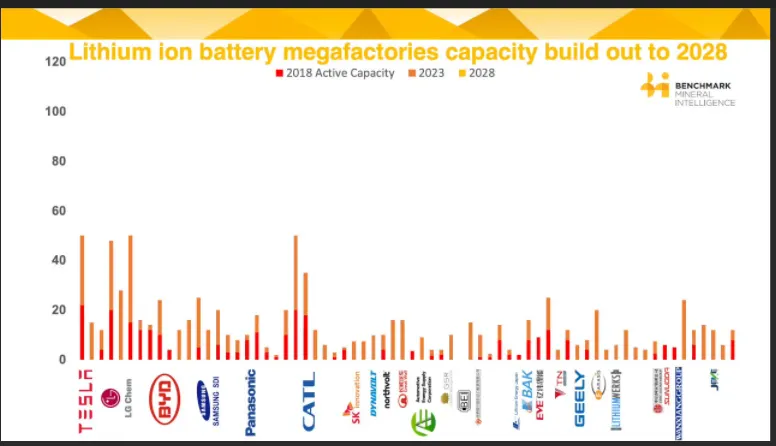
- China dominates the Li-ion battery market. Around three-quarters of battery cell manufacturing capacity is in China, and Chinese companies have unparalleled control of required domestic and foreign battery raw materials and processing facilities.
- India has been importing Li-ion batteries from China, Japan and South Korea.
Lithium-ion Battery – Applications
- Electronic gadgets
- Tele-communication
- Aerospace
- Industrial applications
- Lithium-ion battery technology has made it the favourite power source for electric and hybrid electric vehicles.
Lithium-ion Cell technology – Benefits
- Long life cycle
- High Voltage
- High Storage Characteristics
- High Energy Density
Lithium-ion Battery – Major Issues
- Lithium-Ion batteries can be a safety hazard since they contain flammable electrolytes, and if damaged or incorrectly charged can lead to explosions and fires.
- There have been several incidents involving batteries on Boeing 787s.
- Samsung was forced to recall Galaxy Note 7 handsets following lithium-ion fires
- Requires protection circuit to maintain voltage and current within safe limits.
- Expensive to manufacture – about 40 percent higher in cost than nickel-cadmium.
- Not fully mature – metals and chemicals are changing on a continuing basis.
Block Diagram of Electric Vehicle
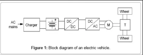
Lets Take the design specification of TATA Nexon Electric Vehicle Drivetrain
Electric Drivetrain
Motor Type- Permanent Magnet Synchronous Motor
Mechanical DC Motor Power-900 W
Drive Mode- Multi Drive modes (Drive & Sports)
Batterypack- 30.2 kWh High energy density Lithium ion battery pack
Thermal Management System - Liquid Cooled
Ingree Protection for Motor and Batterypack- IP 67
Acceleration (0-100km/h in s)- 9.9
Gradeability- 34%
Emission- Zero tailpipe emission
Dimension And Weight
Length xWidthxHeight- 3993x1811x1606
Wheelbase(mm)- 2498
Ground Clearance(mm)- Unladen - 205
Bootspace(l)- 350
Kerb Weight- 680kg
Payload - 70kg
Charging Standard- CCS 2
Estimated regular charging time(SOC 10 % to 90 % from any 15 A plug point- 8.5 hours
Estimated Fast Charging Time(SOC 0 %- 80 %) - 60 min
Vehicle Body System
- The Chassis. The chassis of an automobile incorporates all the major assemblies consisting of an engine, components...
- The Engine. The engine is the source of motive power to an automobile. Obviously, it is a very important part of the...
- The Transmission System. The transmission system transmits power developed by the engine to the road wheels. The...
- The Body. The use of a separate frame to which the body structure is attached is now almost obsolete except for some...
- The Auxiliaries.
- Simulink model of Vehicle body subsytem is as under
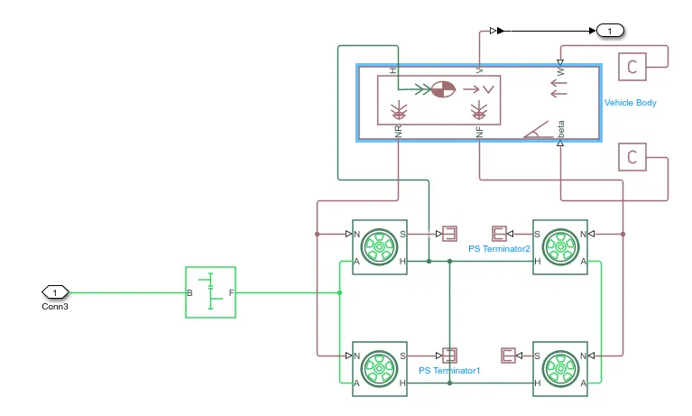
Explaination of VehicleSub system
The vehicle Subsystem Consist of
1. Tire
2. Vehicle body
3. Simple Gear
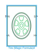
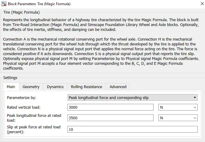
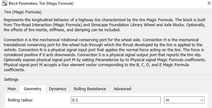
Represents the longitudinal behavior of a highway tire characterized by the tire Magic Formula. The block is built from Tire-Road Interaction (Magic Formula) and Simscape Foundation Library Wheel and Axle blocks. Optionally, the effects of tire inertia, stiffness, and damping can be included.
Connection A is the mechanical rotational conserving port for the wheel axle. Connection H is the mechanical translational conserving port for the wheel hub through which the thrust developed by the tire is applied to the vehicle. Connection N is a physical signal input port that applies the normal force acting on the tire. The force is considered positive if it acts downwards. Connection S is a physical signal output port that reports the tire slip. Optionally expose physical signal port M by setting Parameterize by to Physical signal Magic Formula coefficients. Physical signal port M accepts a four element vector corresponding to the B, C, D, and E Magic Formula coefficients.
Vehicle Body
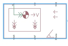
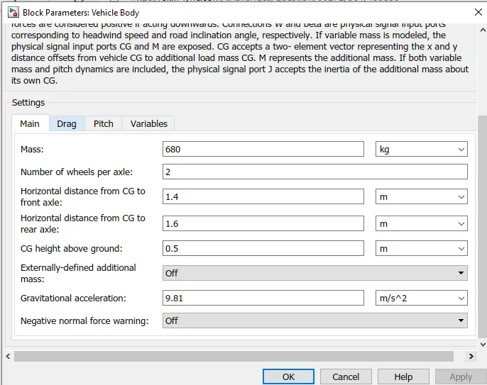
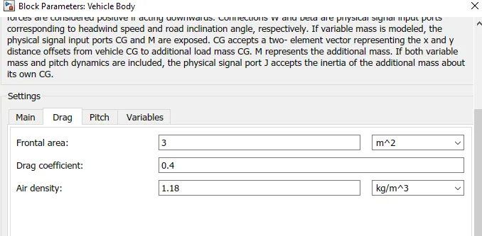
The block accounts for body mass, aerodynamic drag, road incline, and weight distribution between axles due to acceleration and road profile. The vehicle can have the same or a different number of wheels on each axle. Optionally include pitch and suspension dynamics or additional variable mass and inertia. The vehicle does not move vertically relative to the ground.
Connection H is the mechanical translational conserving port associated with the horizontal motion of the vehicle body. The resulting traction motion developed by tires should be connected to this port. Connections V, NF, and NR are physical signal output ports for vehicle velocity and front and rear normal wheel forces, respectively. Wheel forces are considered positive if acting downwards. Connections W and beta are physical signal input ports corresponding to headwind speed and road inclination angle, respectively. If variable mass is modeled, the physical signal input ports CG and M are exposed. CG accepts a two- element vector representing the x and y distance offsets from vehicle CG to additional load mass CG. M represents the additional mass. If both variable mass and pitch dynamics are included, the physical signal port J accepts the inertia of the additional mass about its own CG.
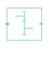
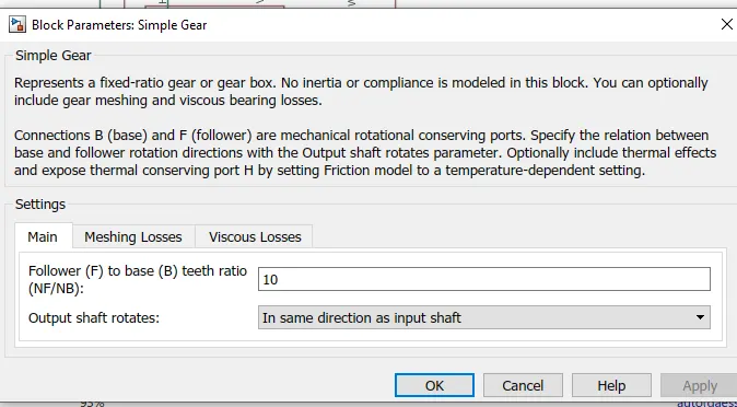
Simple Gear
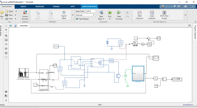
The complete Drivetrain
State of Charge Subsystem
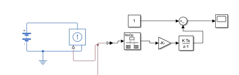
This Subsystem Consist of
1. Battery
2. Current Controlled Source
3.Rate Transition
4. Gain
5. Discrete Time Integrater
6. Subtract Block
7.Scope
8. Electrical reference
Battery
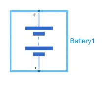
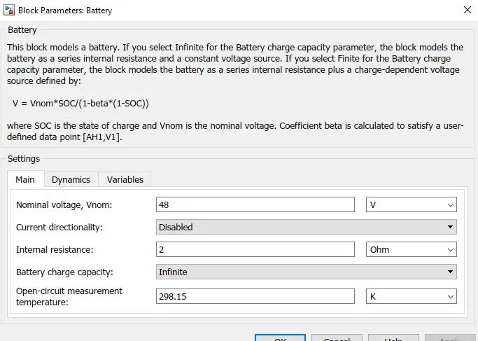
V = Vnom*SOC/(1-beta*(1-SOC))
where SOC is the state of charge and Vnom is the nominal voltage. Coefficient beta is calculated to satisfy a user-defined data point.
Current Controlled Source
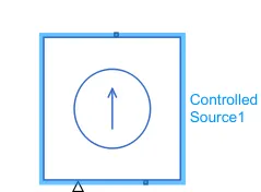
The block represents an ideal current source that is powerful enough to maintain the specified current through it regardless of the voltage across it. The output current is I = Is, where Is is the numerical value presented at the physical signal port.
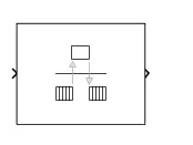
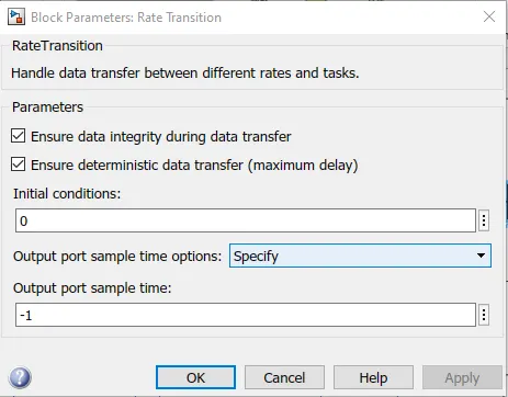
rate Transition
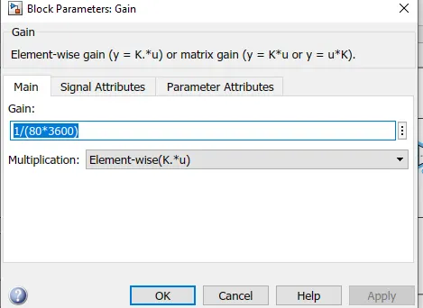
Gain
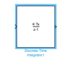
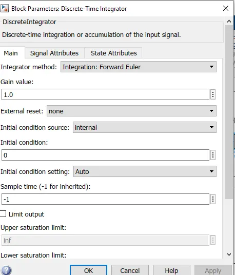
Discrete Time Integrater
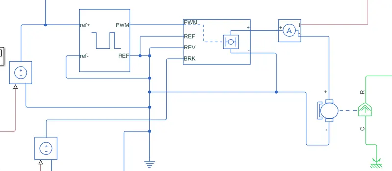
Simulink Model of Motor Controller
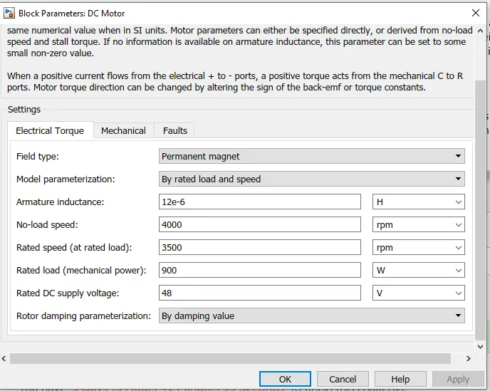
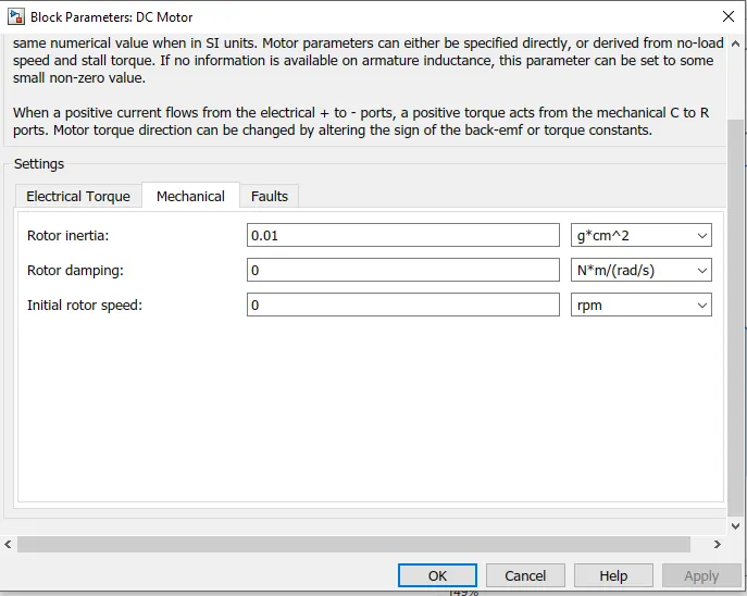
DC Motor
This block represents the electrical and torque characteristics of a DC motor.
The block assumes that no electromagnetic energy is lost, and hence the back-emf and torque constants have the same numerical value when in SI units. Motor parameters can either be specified directly, or derived from no-load speed and stall torque. If no information is available on armature inductance, this parameter can be set to some small non-zero value.
When a positive current flows from the electrical + to - ports, a positive torque acts from the mechanical C to R ports. Motor torque direction can be changed by altering the sign of the back-emf or torque constants.
H bridge
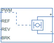
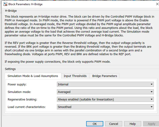
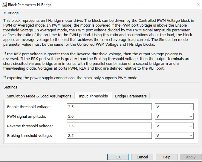
This block represents an H-bridge motor drive. The block can be driven by the Controlled PWM Voltage block in PWM or Averaged mode. In PWM mode, the motor is powered if the PWM port voltage is above the Enable threshold voltage. In Averaged mode, the PWM port voltage divided by the PWM signal amplitude parameter defines the ratio of the on-time to the PWM period. Using this ratio and assumptions about the load, the block applies an average voltage to the load that achieves the correct average load current. The Simulation mode parameter value must be the same for the Controlled PWM Voltage and H-Bridge blocks.
If the REV port voltage is greater than the Reverse threshold voltage, then the output voltage polarity is reversed. If the BRK port voltage is greater than the Braking threshold voltage, then the output terminals are short circuited via one bridge arm in series with the parallel combination of a second bridge arm and a freewheeling diode. Voltages at ports PWM, REV and BRK are defined relative to the REF port.
If exposing the power supply connections, the block only supports PWM mode
Controlled PWM Voltage
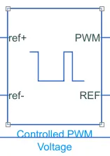
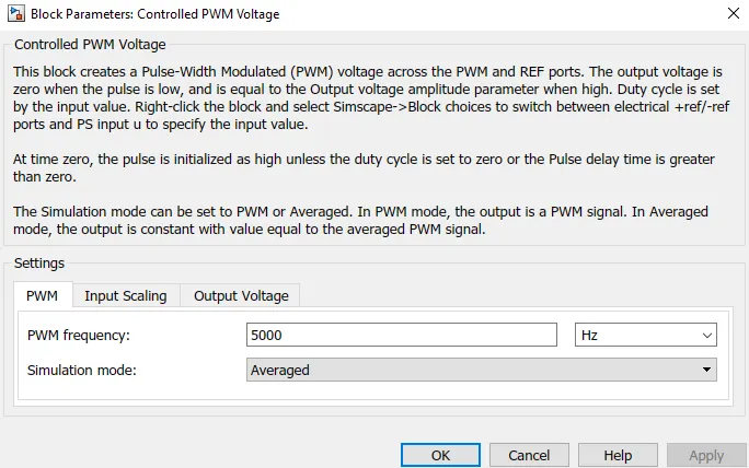
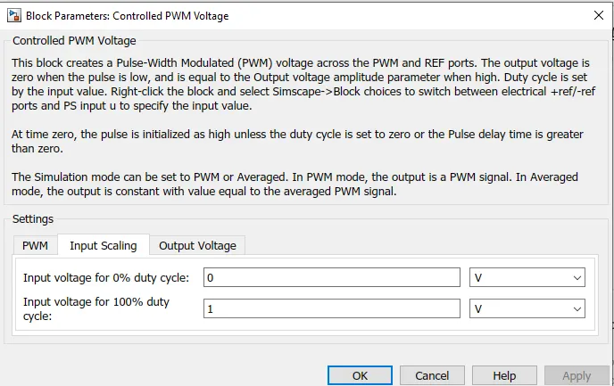
This block creates a Pulse-Width Modulated (PWM) voltage across the PWM and REF ports. The output voltage is zero when the pulse is low, and is equal to the Output voltage amplitude parameter when high. Duty cycle is set by the input value. Right-click the block and select Simscape->Block choices to switch between electrical +ref/-ref ports and PS input u to specify the input value.
At time zero, the pulse is initialized as high unless the duty cycle is set to zero or the Pulse delay time is greater than zero.
The Simulation mode can be set to PWM or Averaged. In PWM mode, the output is a PWM signal. In Averaged mode, the output is constant with value equal to the averaged PWM signal.
Solver Configuration
Exlanation of Motor Controller System
The motor Controller system mainly consist of PWM controlled voltage and H bridge.
H bridge use to control the supply of Battery power from Battery to DC motor. It have four Controlled switches namely PWM, REF, REV, BRK that give controlled DC voltage to DC motor.
Here average mode of Simulation is choosen for faster results compared to PWM mode.
The output Voltafe of DC motor is same as H bridge DC voltage
The Four ports of H bridge , PWM is connected to PWM of PWM controlled sorce. THe REV, REF is connected to the electrical reference. preventing from the reverse operation of DC motor.
THE Drive Cycle SYtem
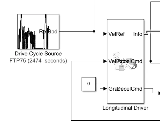
Drive Cycle
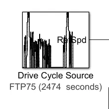
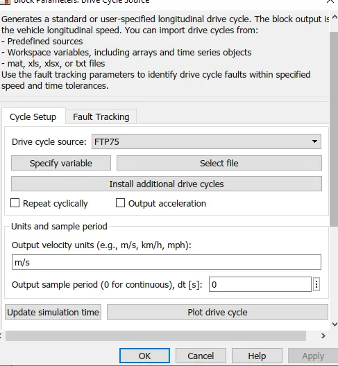
Generates a standard or user-specified longitudinal drive cycle. The block output is the vehicle longitudinal speed. You can import drive cycles from:
- Predefined sources
- Workspace variables, including arrays and time series objects
- mat, xls, xlsx, or txt files
Use the fault tracking parameters to identify drive cycle faults within specified speed and time tolerances.
Longitudnal Driver
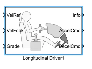
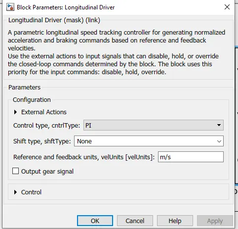
A parametric longitudinal speed tracking controller for generating normalized acceleration and braking commands based on reference and feedback velocities.
Use the external actions to input signals that can disable, hold, or override the closed-loop commands determined by the block. The block uses this priority for the input commands: disable, hold, override.
Results
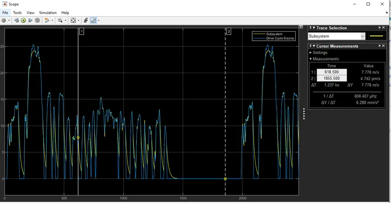
Explaination of the Model
The model was connected according to the above diagram.
The parameters of DC motor was changed to obtained the nearly same graph.
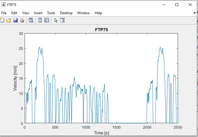
HEre in te results we noticed that drive cycle source and and vehicle speed have approximately same output.
The area under velocity time graph denotes the distance travelled by the vehicle.
The following results were obtained from the simulation with drive cycle FTP75
Drive Cycle FTP75
Distance 5.4 km
Top Speed - 25.2 m/s
Simulation Time 2474 seconds
Vehicle Weight - 680 kg
Frontal area- 3m^2
Drag Coefficient- 0.4
Battery nominal voltage - 48 v
DC motorload/ supply voltage- 900W/ 48 Volts