Final Project: Design of an Electric Vehicle
Create a MATLAB model of electric car which uses a battery and a DC motor. Choose suitable blocks from Powertrain block set. Prepare a report about your model including following:
Objectives:
1. System level configurations
2. Model parameters
3. Results
4. Conclusion
Introduction
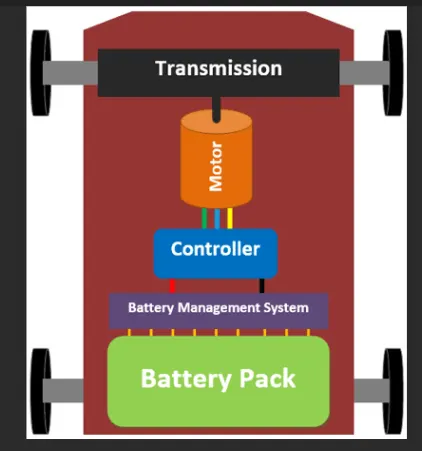
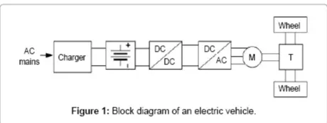
An electric vehicle (EV) is one that operates on an electric motor, instead of an internal-combustion engine that generates power by burning a mix of fuel and gases. Therefore, such as vehicle is seen as a possible replacement for current-generation automobile, in order to address the issue of rising pollution, global warming, depleting natural resources, etc. Though the concept of electric vehicles has been around for a long time, it has drawn a considerable amount of interest in the past decade amid a rising carbon footprint and other environmental impacts of fuel-based vehicles.
In India, the first concrete decision to incentivise electric vehicles was taken in 2010. According to a Rs 95-crore scheme approved by the Ministry of New and Renewable Energy (MNRE), the government announced a financial incentive for manufacturers for electric vehicles sold in India. The scheme, effective from November 2010, envisaged incentives of up to 20 per cent on ex-factory prices of vehicles, subject to a maximum limit. However, the subsidy scheme was later withdrawn by the MNRE in March 2012.
The simulink model is considered is shown below
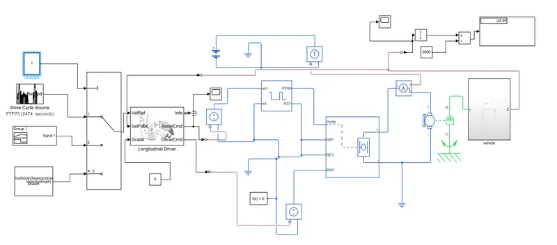
Discussion of eack block is detail.
Vehicle body block
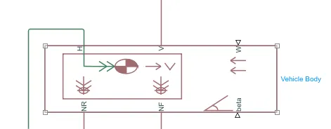
This block consist of 6 ports which can be used to model the electric vehicle
they are
1. H- This is called hub.It is used to connect with vehicle body
2. V - This is called velocity, which is used as physical signal as a output of vehicle body.
3. W- This is physical signal output port used to model headwind acting on the Vehicle.
4. NR- This is physical signal output port used to model rear weel normal forces.
5. NF- This is physical signal output port used to model front wheel output forces.
6. Beta- This is physical signal input port which is model the vehicle on th ebasis of inclination angle to calculate the hill climbing forces.
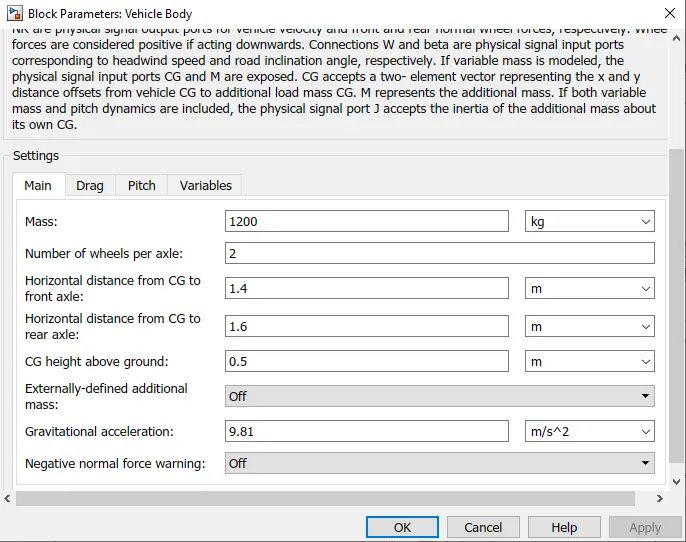
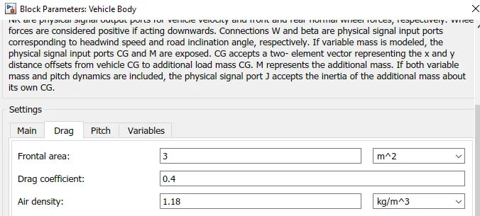
Drag tab
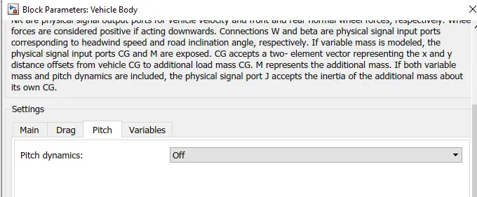
Pitch tab
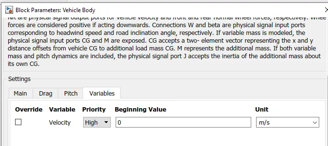
Variable tab
Tyres
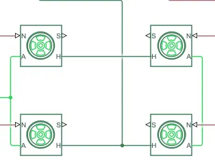
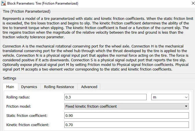
N- Normal
S- Slip
A- Axle
H- Hub
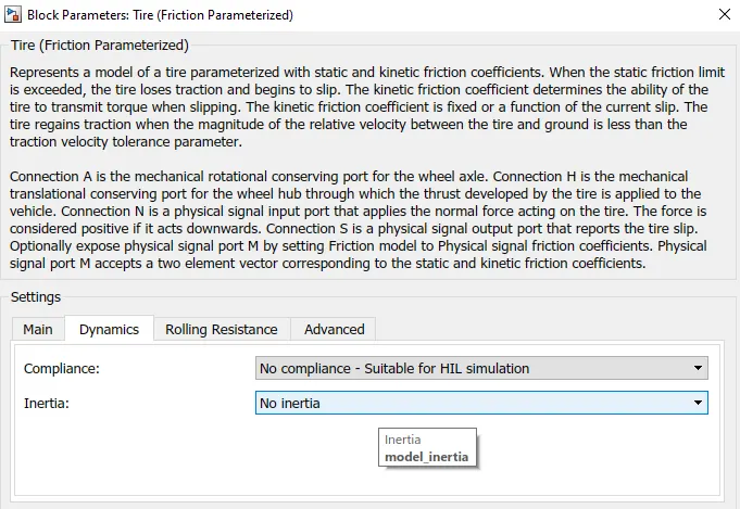
Dynamics tab
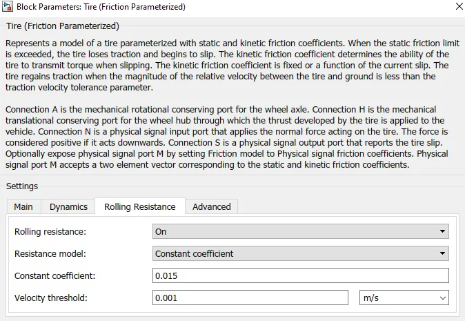
Rolling Resistance Tab
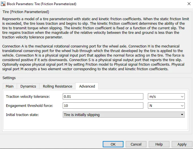
Advanced tab
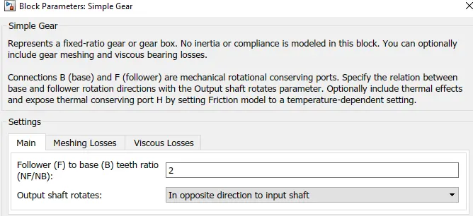
3. Gear

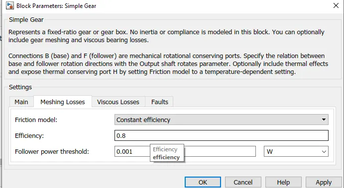
Meshing losses
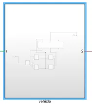
Vehicle subsystem
Connection are made as per diagram
DC Motor
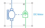
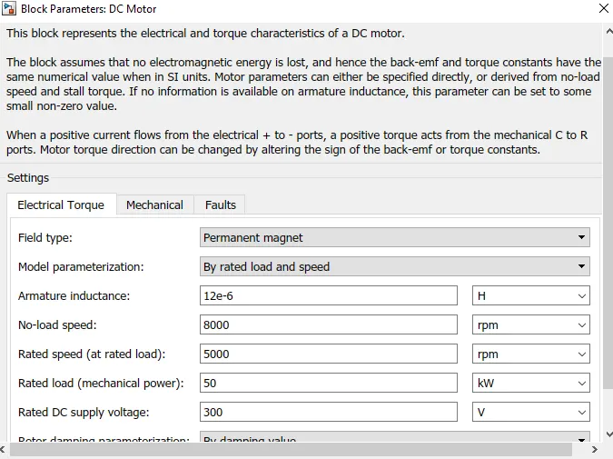
The block assumes that no electromagnetic energy is lost, and hence the back-emf and torque constants have the same numerical value when in SI units. Motor parameters can either be specified directly, or derived from no-load speed and stall torque. If no information is available on armature inductance, this parameter can be set to some small non-zero value.
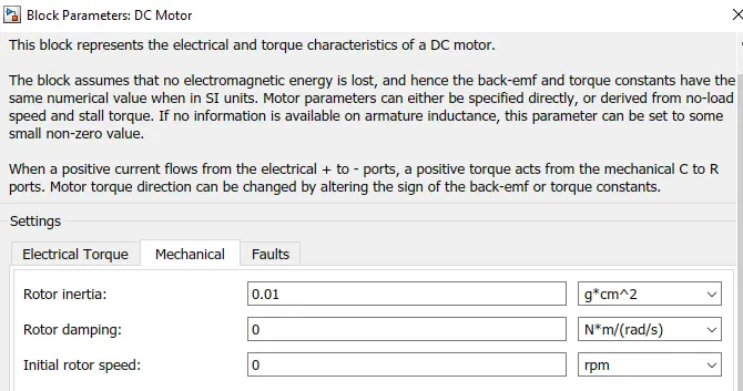
Mechanical tab
From the above diagram we can see that there are two ports of block input and output.
left side is electrical and right side is mechanical. Mechanical ports have two ports C and R. C stands for casing and R stands for rotation of motor. Electrical side has positive and negative for application of voltage. The direction of the torque produced of the DC motor can be changed by the back emf or the torque constant. C port is connected to the mechanical refernce frame so that ist will be stationary. R port is connected to the gear of vehicle body block. positive terminal of electrical side is connected to the positive terminal of power converter ( H bridge).
Power Converter
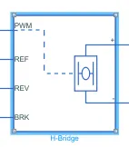
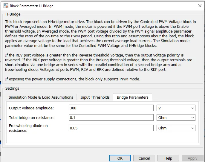
H bridge consist of four ports
PWM- This is Pulse width modulation which gives voltage pulses to H bridge in pwm or average mode.
Ref- Reference
Rev - Reverse
Brk- Break
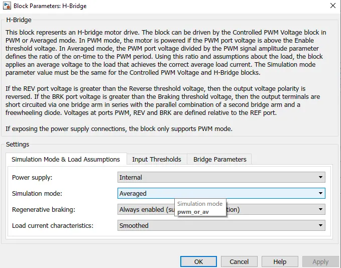
Input Threshold
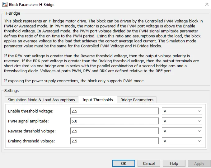
Bridge parameters
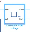
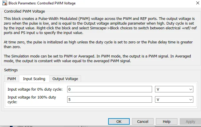
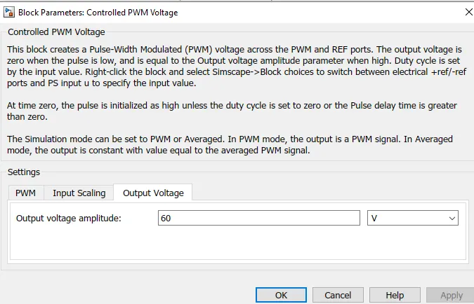
Controlled PWM Voltage Block
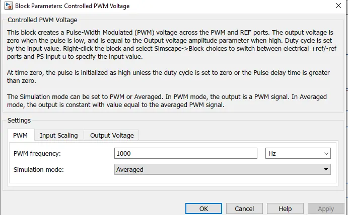
Input scaling
output Voltage
Controlled Voltage Source

The block represents an ideal voltage source that is powerful enough to maintain the specified voltage at its output regardless of the current passing through it. The output voltage is V = Vs, where Vs is the numerical value presented at the physical signal port.
Electrical reference

Electrical reference port. A model must contain at least one electrical reference port (electrical ground).
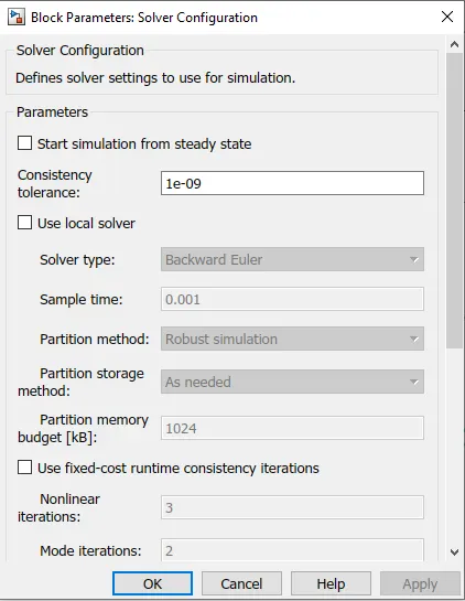
Solver Configuration

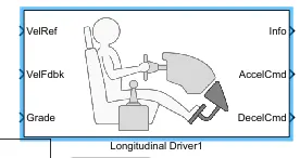
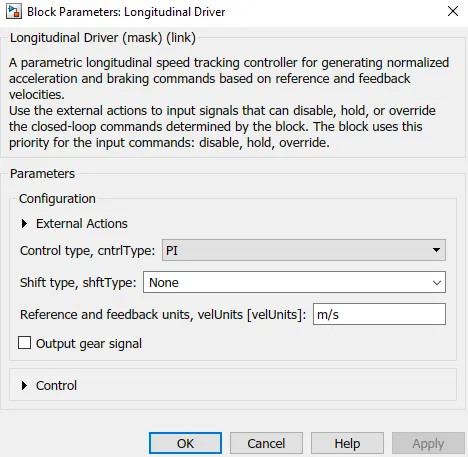
Longitudnal Driver
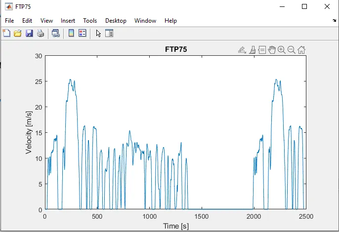
Drive Cycle
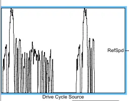
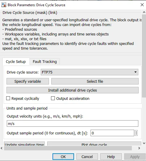
Generates a standard or user-specified longitudinal drive cycle. The block output is the vehicle longitudinal speed. You can import drive cycles from:
- Predefined sources
- Workspace variables, including arrays and time series objects
- mat, xls, xlsx, or txt files
Use the fault tracking parameters to identify drive cycle faults within specified speed and time tolerances..
Battery system
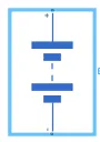
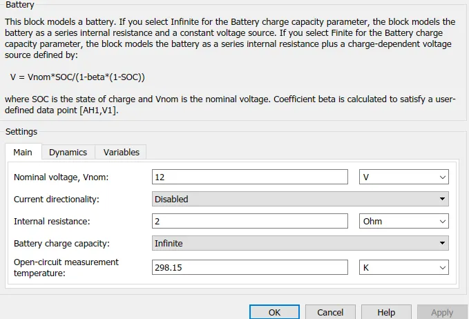
This block models a battery. If you select Infinite for the Battery charge capacity parameter, the block models the battery as a series internal resistance and a constant voltage source. If you select Finite for the Battery charge capacity parameter, the block models the battery as a series internal resistance plus a charge-dependent voltage source defined by:
V = Vnom*SOC/(1-beta*(1-SOC)), where SOC is the state of charge and Vnom is the nominal voltage. Coefficient beta is calculated to satisfy a user-defined data point.
Current Sensor
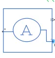
The block represents an ideal current sensor, that is, a device that converts current measured in any electrical branch into a physical signal proportional to the current. Connections + and - are conserving electrical ports through which the sensor is inserted into the circuit. Connection I is a physical signal port that outputs current value.
Results