Week-6 Challenge: EV Drivetrain
1. Which types of power converter circuits are employed in electric and hybrid electric vehicle?
Power converter technology deals with the processing and controlling the flow of electrical energy in order to supply the voltage and current in form that optimally suited for the end user requirement.
Power electronic converter uses power electronic component such as IGBT, MOSFET, TRAIC etc in order to supply voltage and current.
The ultimate aim of power electronic converter is to provide conditioning power for certain application.
Block diagram of power electronic system used in EV and HEV
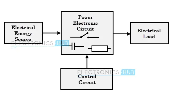
The bolock diagram explains about electrical energy source, power electronic circuit, control circuit, electrical load.This converts one form of electrical energy to another form. The energy transfer from source to load is done by power electronic switches (SCR, TRIAC)
Different types of power converter circuits which are employed in electric and hybrid elecric vehicle are as follows-
1.Inverter (dc to ac)
2. Rectifier (ac to dc)
3. Chopper (dc to dc)
4. Regulator ( ac to ac)
Inverter
It is device or a circuitary that converts direct current power into alternating current power . The electrical frequency develop depends upon the device employed in it. The voltage , current and power rating depends upon the cicuitry. The inverter doesnot produce the power it is done by dc power source.
In some situations like when the DC voltage is low then we cannot use the low DC voltage in a home appliance. So due to this reason, an inverter can be used whenever we utilize solar power panel.
According to the Type of Load
- Single-phase Inverter
- Three-phase Inverter
1) single-phase inverter
Generally, residential and commercial load uses single phase power. The single-phase inverter is used for this type of application. The single-phase inverter is further divided into two parts;
- Single Phase Half-bridge Inverter
- Single Phase Full-bridge Inverter
A) Single Phase Half bridge Inverter
This type of inverter consists of two thyristor and two diodes and connection is as shown in below figure.
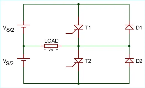
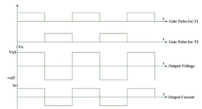
n this case, total DC voltage is Vs and divided into two equal parts Vs/2. Time for one cycle is T sec.
For half cycle of 0
For the second half cycle of T/2
Vo = Vs/2
B) Single Phase Full-bridge Inverter
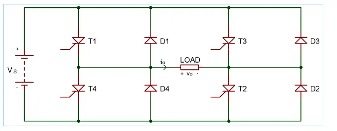
In this type of inverter, four thyristors and four diodes are used. The circuit diagram of single-phase full bridge is as shown in below figure.
2) Three Phase Bridge Inverter
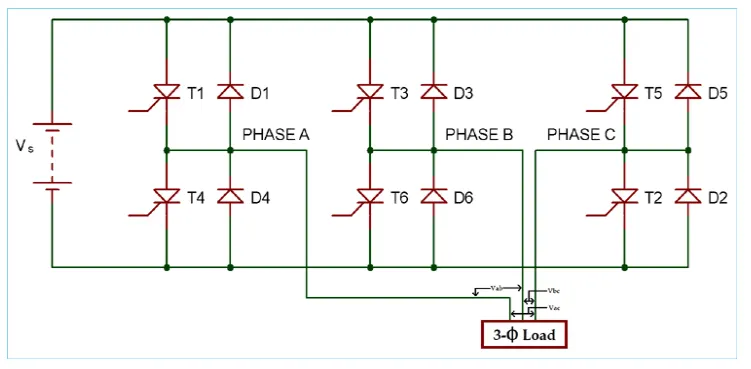
Rectifier (ac to dc)
The main purpose of the diode rectifier is to take the RMS AC voltage and convert it to a DC voltage. For the design of the Plug-In Hybrid Electric Vehicle Converter an uncontrolled diode rectifier will be used. The Figure represents the general circuit for an uncontrolled diode rectifier.
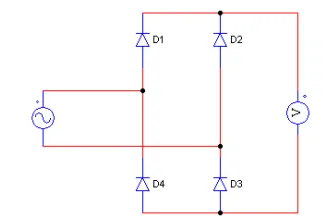
When the input voltage is positive, D1 and D3 diodes are conducting. These are then forward biased. D2 and D4 are in the “off” states when D1 and D3 are conducting. Furthermore, when the input voltage is negative, D2 and D4 are now conducting while D1 and D3 are then in the “off” states or not conducting. The switching functionality of the diodes converts the sinusoidal wave input into a rectified sine wave.
CHOPPER
It converts constant to variable dc or variable dc to constant dc.
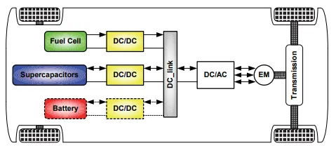
IN electrical engineering dc dc converter is category of power converters which converts the source dc voltage from one voltage level to another voltage level, by storing the input energy completely or totally giving it to the other circuit.
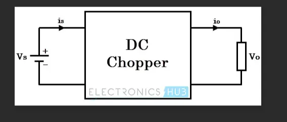
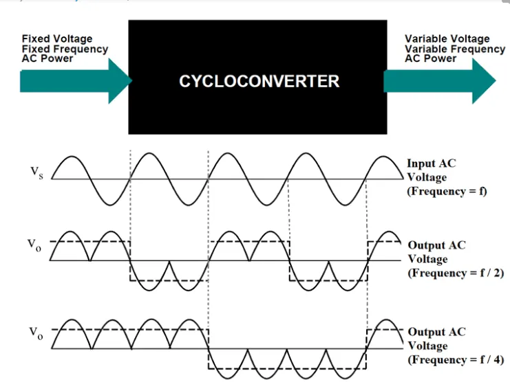
AC to AC converters
These are also called as cycloconverters. these converters converts voltage level from one frequency to another frequency.
These are used in different types of application like uninterrupted power supply, high power ac to ac transmission, adjustable speed drives , renewable energy conversion system, aircraft conversion system.
2. An Electric Vehicle's powertrain with 72V battery pack in shown in the diagram below. The duty ratio for acceleration operation is 'd1' and for the braking operation the duty ratio is 'd2'.
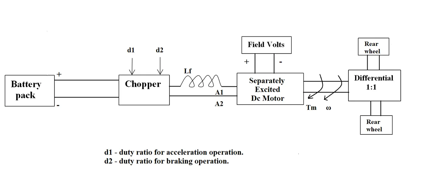
The other parameters of the electric vehicle is given below,
Motor and Controller Parameters:
Rated Armature voltage= 72 V
Rated armature current= 400 A
Ra= 0.5Ω, KΦ= 0.7 Volt second
Chopper Switching frequency= 400 Hz
The vehicle speed-torque characteristics are given by the below equation

What is EV steady state speed if duty cycle is 70%?
Solution
V = 72 volts, Ia = 400 amps, Ra = 0.5 ohms, kϕ= 0.7 volts second
Motor torque equation is given by
T= (PZ/A)*(Ia/2)
T = k Ia
T= 0.7 x 400 =280Nm
given that duty cycle is 70% then,
V x duty cycle= 72x0.7= 50.04 volt
vehicle speed torque equation is given by
Now according to speed torque characteristics of dc machine Torque equation is given as
T= V.kϕ/Ra-ω.(kϕ)^2/Ra,
where T is motor torque, v is voltage, kϕ is motor constant, Ra is armature resistance, ω is motor speed
Now by substituting the value
T= 50.4*0.7/0.5-ω.(0.7)^2/0.5
T= 70.56-0.98ω^2
now equating both equation we get
ω= 38.85rad/sec.
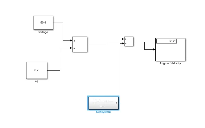
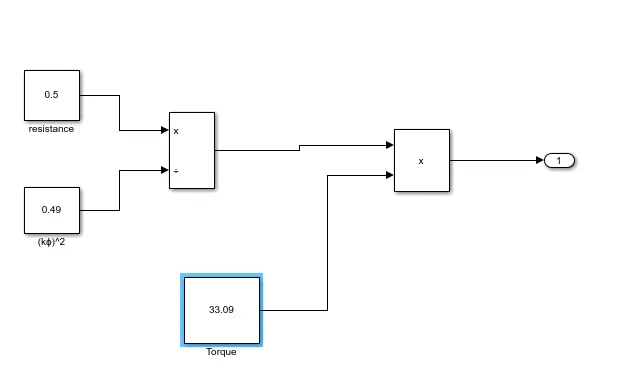
3.. Develop a mathematical model of a DC Motor for the below equation using Simulink.
ω">ω= V/Kϕ"> -Ra/Kϕ">ϕ^2 .T
subsyatem
4.Induction versus DC brushless motors by Wally Rippel, Tesla
Explain in brief about author’s perspective.
Author had focussed on the Ev based on brushless DC motor and Induction based motor.
According to him Dc motors are replaced by DC brushless mptors and Induction motors.
Also lead acid battery is replaced by lithium ion battery for electric vehicles.
He clearly mentioned that there is great future of both induction based motor and brushless dc motor which depends upon the use.
BLDC Motor-
With brushless dc motor, rotor include two or more permanent magnets, that generate the magnetic field. The magnetic field enters the stator core ( core made up of thin stacked lamination), and link with the current flowing through the winding, and the interaction with these stator and rotor leads to production of torque. Rotor rotates such that magnitude and polarity of stator current is continously varied such that torque remains always constant. This ensure the conversion of electrical to mechanical energy is optimally efficient. Inverter used here is for current control.
3 Phase Induction motor-
The technology behind the induction motor is the use of 3 phase induction motor which was discovered by NIKOLA TESLA. Here steel laminated device is used instead of magnets. Current produce in stator winding produces the rotating magnetic field that enters the rotor. In Induction motor current interactc with generating magnetic field produces by stator generates the force needed for rotor torque. Induction motor is compatible with power source and works on ac supply voltage.