Week-11 Challenge: Braking
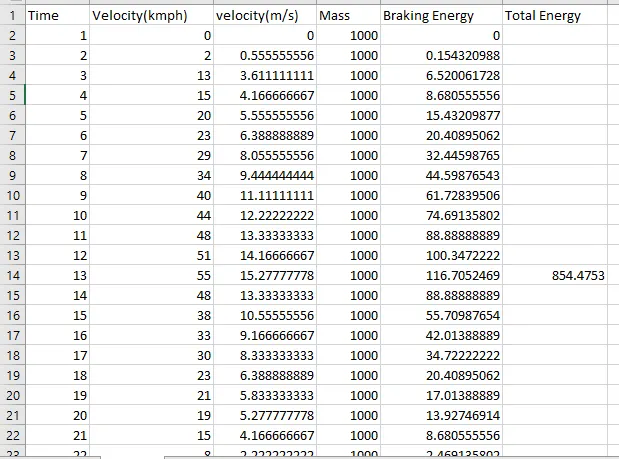
- For a defined driving cycle, calculate the energy required for braking.
Energy required for braking
Braking energy = 0.5*mass * velocuty^2
2.Why electric motor can’t develop braking torque at high speed similar to starting? How electric and mechanical brakes are coordinated?
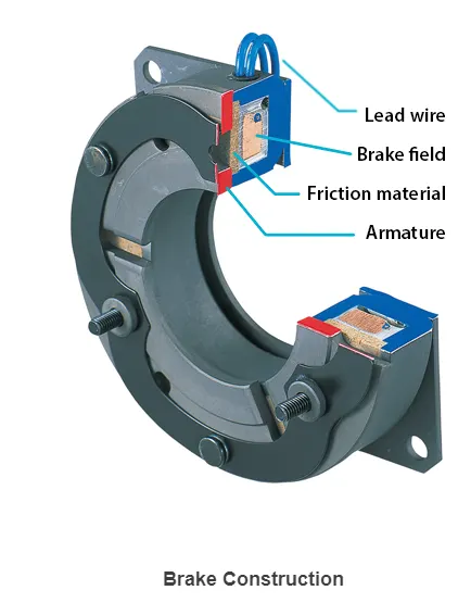
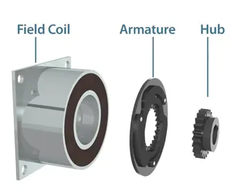
Braking system for electric motor
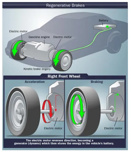
Working of regenerative braking
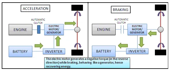
Regenerative Braking in Hybrid Electric Vehicle
1) Braking by d.c. injection
In this method,it disconnected the a.c and d.c supply to the stator winding to created torque for braked the drive or electric motor.
The impact from power supply disconnected is it created magnetic static field in to the rotor area and current will generated in the rotor winding to produces high breaking torque.This method also use in a shut wound d.c motor.
Basically a d.c power supply need to provide for this method and it ca get from build in rectifier system in the controlled system.
Basic operation
To stop the driven or electric motor,we need to push in the stop button and it made the contactor is open and the d.c contactor is close position.It made the stator connected with rectifier to receive the d.c power supply.
After that the motor is rapidly brought to rest.It controlled by a timer delay relay to set the varying period for application of d.c supply to load the motor stator and d.c contactor de-energize.Please refer to diagram below.

2) Braking by reversal (plugging)
These method is common used for rapid braking of a.c. and d.c. motors.To stop the drive,the braking controlled was reconnecting the winding to the supply to corresponding to reversed direction may of drive rotation either clock wise or anti-clock wise.
It must perform in quickly action controlled by magnetic contactor wit automatic control system.The controller must suitable with drive or electric application to ensure it can stop it when is needed.
When deceleration is completed and the motor stops, it will of course reverse unless the windings are disconnected.It not suitable for the normal starting gear required for an induction motor because it will damage the driven system.The motor requirement and drive system must be high consideration before applied this braking method.
Coordinatination of electric and mechanical brakes
Motor in elecric vehicle can be used can be used as brake regeneratively , here braking energy can be recycled to charging the battery used in electric vehicle. Braking stability of electric vehicles with electro hydraulic hybrid braking system can be influenced by braking force distribution between hydraulic braking force and regenerative force. Due to this regenerative braking of electric vehicles the need of hydraulic braking is reduced.
But there are some limitation, like the maximum deacceleration time with engine is far smaller than the brake assistance, so need of ordinary frictional brake is also required to make the vehicle stop instantly.
Brake control strategy
Regenerative braking is one of the most effective deceleration control methods in case of electric and hybrid vehicles. The properly controlled regenerative braking force of the electric motor(s) brings better braking safety, shorter braking distance, and less depreciation of the brakes if accompanied by the hydraulic braking modules.
When the brake pedal is pressed, the electric motor is treated as a generator to produce negative torque. In this scenario the produced energy can be either dissipated or used to charge the batteries. In this paper, based on the registered brake strength, the braking force is calculated. Accordingly, employing a braking torque distribution strategy between the regenerative braking torque and the hydraulic braking torque, the proper braking torques are determined and the optimal slip ratio is reached by adjusting the braking torques.
An anti-lock regenerative braking strategy is proposed to attain anti-slip control for negative accelerations.
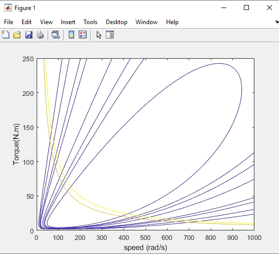
3. Make a MATLAB program which plots contour of given motor speed, torque and efficiency values. Attach the code as a .m file attach a screenshot of all the plots.
clear all
close all
clc
w=linspace(0,1000);
T=linspace(0,250);
%motor constants
kc=0.2;% for copper loss
ki=0.008;% for iron loss
kw=0.00001;% for windgae loss
conL=20;% for constant motor losses
% making mess
[X,Y] = meshgrid(w,T);
Outputpower = (X.*Y);%Torque * Speed = power
B=(Y.^2)*kc;%copper loss
C=(X.^3)*kw;%windage loss
D=X*ki;%iron loss
Inputpower = Outputpower + B + C + D + conL;
Z= Outputpower./Inputpower;
%set the efficiencies for which the control will be plotted
V= [0.70,0.75,0.80,0.82,0.87,0.89,0.90,0.92];
box off
grid off
contour(X,Y,Z,V)
xlabel('speed (rad/s)')
ylabel('Torque(N.m)')
hold on
V= [8000, 10000];
contour(X,Y,Outputpower,V)